
Home Porting Techniques


Registered User
Joined: Nov 2008
Posts: 383
IMG_20150117_092510_zpsdc1d9029.jpg
Went to the flow bench with a C casting. Both Dave (the Freak) and myself had our ports flowed. The premise was simple. Have the best flowing port with just a valve job and bowl work. Dave kept it conservative and I went a little further to see the difference. Heads were flowed at 28" and all heads listed had 2.07" intake valves.
Here is the flow bench results:
80 Rocket port:
.100- 64
.200- 132
.300- 192
.400- 223
.500- 250
.600- 267
The Freak port:
.100- 69
.200- 132
.300- 193
.400- 223
.500- 248
.600- 260
For comparison purposes here is a Joe Mondello race port C which was flowed on the same flow bench a few months ago:
.100- 67
.200- 140
.300- 188
.400- 222
.500- 247
.600- 268
.700- 280
These ports are preliminary testing. We still are working with different valve jobs and we did not backcut the valves. There is another ace up our sleeve, but that will be a teaser to keep you tuned into this thread.
Thread Starter
Registered User
Joined: Apr 2010
Posts: 988
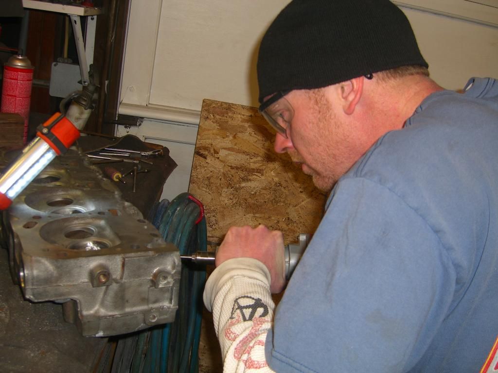
Wish I could have gone with to see our heads flowed. I had a feeling Don's bowl was going to flow better than mine. We wanted to do them a little different. I was really surprised about the exhaust port flow numbers. Kind of hard to believe just a good bowl blend and valve job could be right there with the Edelbrocks & much better than the Pro Comps. There's a lot of room for improvement. Don did all his port work with an electric grinder, and I used air. Here's some action shots-
CIMG4753.jpg
CIMG4760.jpg
CIMG4761.jpg
CIMG4763.jpg
CIMG4764.jpg
CIMG4776.jpg
CIMG4775.jpg
This was a lot of fun and interesting results. We did not remove any bumps or work any of the ports other than the bowl area. These tests should be just what the Doctor ordered.

CIMG4753.jpg
CIMG4760.jpg
CIMG4761.jpg
CIMG4763.jpg
CIMG4764.jpg
CIMG4776.jpg
CIMG4775.jpg
This was a lot of fun and interesting results. We did not remove any bumps or work any of the ports other than the bowl area. These tests should be just what the Doctor ordered.
Thread Starter
Registered User
Joined: Apr 2010
Posts: 988
X-peri-mental Port Work
I spent most of the day working on the junk E casting Jeremy gave me. I decided to raise the roof and floor of one of the exhaust ports. I have a lot of hours into this. I hope it does well on the flow bench. This head is just to see what type of results could be had in a max effort cast iron head. John from Rocket Racing gave me the idea to weld externally above the port, then start grinding. He also suggested the "D" shape. I went a little crazy here-
CIMG4780.jpg
CIMG4783.jpg
CIMG4782.jpg
CIMG4787.jpg
CIMG4780.jpg
CIMG4783.jpg
CIMG4782.jpg
CIMG4787.jpg

Registered User
Joined: Nov 2008
Posts: 383
I do want to mention that Dave, nor myself are hung up on flow numbers. We look to have a small block and big block dynoed in the upcoming months to substantiate the flow numbers. And from there.......ET slips........
Registered User
Joined: Nov 2008
Posts: 383
I am not basing the Edelbrock flow numbers off of their website (new heads) because everything I have heard is they are quite inflated (by about 10cfm). The flow bench we tested on showed that as well.


Registered User
Joined: Jan 2015
Posts: 6
I've been watching this thread for a while and thought I might contribute some minor information. Hopefully this won't derail the thread. I recently filled the crossovers and did some port work to my KA heads for my jet boat. Melting the aluminum was one of my big challenges because I don't have a oxy/ace torch. The method I found was to use a brush burner that I bought from Harbor Freight for $16 dollars. I broke up an old aluminum impeller from a Berkeley jet pump. The impeller was broken up into smaller pieces and placed in a stainless steel flour container. The brush burner took about 5-6 minutes to melt the aluminum. The pour went smooth.
Thread Starter
Registered User
Joined: Apr 2010
Posts: 988
I've been watching this thread for a while and thought I might contribute some minor information. Hopefully this won't derail the thread. I recently filled the crossovers and did some port work to my KA heads for my jet boat. Melting the aluminum was one of my big challenges because I don't have a oxy/ace torch. The method I found was to use a brush burner that I bought from Harbor Freight for $16 dollars. I broke up an old aluminum impeller from a Berkeley jet pump. The impeller was broken up into smaller pieces and placed in a stainless steel flour container. The brush burner took about 5-6 minutes to melt the aluminum. The pour went smooth.
Do you have any photos to share? The next one I do I'm going to check temps/ melting point.
Registered User
Joined: Jan 2015
Posts: 6
Here are a few pictures. This is my first attempt with porting and filling crossovers. In a couple of months I'll test the boat out and see if I improved them or not. I figured the worst case scenario would result in a pair of new aluminum heads.
Chevy budget Olds powered
Joined: Jul 2011
Posts: 8,638
From: Elgin, Illinois
Ok so today I was working on the cylinder heads the freakman ( 67cutlassfreak) poerted for me. I have already got the spring heights all set up ., but when I did that I checked for valve lift clearance and figured out I did not have nearly enough. So I studied the subject and there are a few options like .050 locks and retainers that will give you more valve lift clearance by raising the retainer. That's an option but it will throw your installed spring heights off. In my situation I don't even think I would be able to run that many shims under the spring., so I bit the bullet and ordered the tool that comp cams sells to cut the guide to fit Viton seals . This tool does 2 things it cuts the diameter of the guide for the seal to fit properly and it will also cut the height down.
Here is what I used Nothing fancy . I opted against a drill because the cutting bits are brazed on and from experience with machining sometimes a slower cut yields a much better cut. My main thing for using the speed wrench with a 12 point 10mm socket was to not trash the bit if it happen to dig into the metal which at high speeds would mess things up. This tool cuts pretty good with a speed wrench to be honest and there is less room for error.


Now The area to check for adequate valve lift clearance is between the very bottom point of the retainer and top of the seal . Lunati recommends .090 . I had 565 on this measurement I was checking with the seal I had but once I get the correct seal it will open up more .This is explained later.

Now this is what the cut guide looks like. I made only a .075 cut because I got a .500 cutter I ordered a .530 but got the wrong one. Seals are cheap enough so I just gotta order new Viton seals for the smaller diameter.

Im showing this because many guys wanna do just a bigger cam but it really is not that simple. With a Viton seal I had just a bit over .500 clearance., the heads where previously cut for Viton seals. Checking for clearance is not that hard and the tool is only about 85 bucks. You get to do 2 things though. You get to make sure you have enough clearance and you get to upgrade to a much better stem seal.
Now My question for the olds pro's is how much can you cut down the guide? Obviously im not trying to cut it down to nothing but everywhere I look I cant seem to find this info. What is the same margin for bringing the guide down ?
I had to re type this 3 TIMES lol. First post was much more detailed and after doing it 3 times I had to condense it a little for my sanity.
Here is what I used Nothing fancy . I opted against a drill because the cutting bits are brazed on and from experience with machining sometimes a slower cut yields a much better cut. My main thing for using the speed wrench with a 12 point 10mm socket was to not trash the bit if it happen to dig into the metal which at high speeds would mess things up. This tool cuts pretty good with a speed wrench to be honest and there is less room for error.
Now The area to check for adequate valve lift clearance is between the very bottom point of the retainer and top of the seal . Lunati recommends .090 . I had 565 on this measurement I was checking with the seal I had but once I get the correct seal it will open up more .This is explained later.
Now this is what the cut guide looks like. I made only a .075 cut because I got a .500 cutter I ordered a .530 but got the wrong one. Seals are cheap enough so I just gotta order new Viton seals for the smaller diameter.
Im showing this because many guys wanna do just a bigger cam but it really is not that simple. With a Viton seal I had just a bit over .500 clearance., the heads where previously cut for Viton seals. Checking for clearance is not that hard and the tool is only about 85 bucks. You get to do 2 things though. You get to make sure you have enough clearance and you get to upgrade to a much better stem seal.
Now My question for the olds pro's is how much can you cut down the guide? Obviously im not trying to cut it down to nothing but everywhere I look I cant seem to find this info. What is the same margin for bringing the guide down ?
I had to re type this 3 TIMES lol. First post was much more detailed and after doing it 3 times I had to condense it a little for my sanity.
Last edited by coppercutlass; Feb 8, 2015 at 02:00 PM.
Registered User
Joined: Nov 2008
Posts: 383
Now My question for the olds pro's is how much can you cut down the guide? Obviously im not trying to cut it down to nothing but everywhere I look I cant seem to find this info. What is the same margin for bringing the guide down ?
I had to re type this 3 TIMES lol. First post was much more detailed and after doing it 3 times I had to condense it a little for my sanity.
Registered User
Joined: Nov 2008
Posts: 383
In an effort to make this the most comprehensive resource on Oldsmobile cast iron cylinder heads on the interwebs........I got some more info for everyone to digest.
I checked the intake runner port size as measured in cc's.
#3 head- 1.875 valve, stock 151cc
#4 head- 2.07 valve, bowl work/guide work 163cc
G head- 2.00 valve, stock 163cc
E head- 2.00 valve, stock 165cc
C head- 2.00 valve, stock 171cc
Ga head- 2.07 valve, .160 raised roof, bowl/guide work 178cc (these heads are on my 80 Cutlass with a 355 small block)
Also, in the big block head variety, it seems the C castings and all prior heads have a taller roof inside the port by about .150" compared to the E and G head varieties.
Last edited by 80 Rocket; Feb 12, 2015 at 08:35 PM.

Registered User
Joined: Feb 2010
Posts: 1,587
From: West Michigan
Registered User
Joined: Nov 2008
Posts: 383
But I am not 100%. Gotta cut some more heads in half. Who's got bad castings that are cracked/damaged that they want to donate to the cause?
Thread Starter
Registered User
Joined: Apr 2010
Posts: 988
Still Porting
I can't hardly believe how many views this thread has gotten since I started it. I'm glad there's a bunch of do-it-yourself-ers still out there. Porting heads is not really hard work, just very time consuming. Over the past year and a half I have learned a lot, and developed my own techniques. I have been aproached by a few people, and am on my third set of small block heads, over the past two months. I really do enjoy this stuff. I know I'm goofey in the head.
Over this past winter I have improved the lighting, insulation, and organization of my garage. Including my porting station. Check it out-
122-2213_IMG_zpsagzh5ctz.jpg
122-2214_IMG_zpsjjbdjcuj.jpg
I installed a six bulb flourescent fixture directly above my work station with a magnetic tool holder mounted to it. I also picked up a diamond stone shaper from Harbor Freight for less than $10. This thing works slick. I've had trouble finding stones shaped just right. Now I can make my own modifications-
122-2211_IMG_zpszz4ccxsd.jpg
I have gotten a little faster by using the right bits and stones for each task at hand. I have come to the conclusion that doing home porting without some seat grinding equipment, would be extremely difficult. You would be basically guessing where the lowest angle of the valve job ends. If you plan on doing more than one set of heads you should pick up a used valve seat grinder, a stone dresser, and some various sizes of stones. If your planning on doing only one set, I suggest you talk to your machine shop and see if they would be willing to rough in the valve job. That way you can do your port work, not worry too much about nicking the seats, and take it back for the finish clean up valve job.
Here's some unported intake bowls, & two that I just finished tonight-
122-2216_IMG_zpsyuf9qhfr.jpg
122-2217_IMG_zpsmikgjyxu.jpg
122-2218_IMG_zpsrlvmohfn.jpg
122-2219_IMG_zps2xeimpyt.jpg
122-2224_IMG_zpsaflrsinr.jpg
I still believe there is a demand for quality cast iron port work. I have been working with my good friend Don (80 Rocket), to develop a strategy to supply a quality product, with the best parts and machining, at an affordable price. We have some ambitous plans, but we need to do a bit more research, before we introduce our offerings to the Olds community.
I suggest that every body that has an pinion, on what they want or need for cast iron heads, goes here, and expresses their opinion-
https://classicoldsmobile.com/forums...ad-thread.html
Last edited by 67 Cutlass Freak; Mar 22, 2015 at 08:21 AM.


Thread Starter
Registered User
Joined: Apr 2010
Posts: 988
Ready Set Port!
Recently someone commented that it should take 3-4 hours to port a head. There is no way in hell I can do it that fast. Maybe I'm just too slow or meticulous. I thought it would be fun to do a little actual time posting from beginning to end of one intake port. So if anyone wants to race me... get your safety glasses, paper face mask (screw that), and stock your fridge. Oh crap there's only 3 in there. At least it's good beer.
These heads belong to a friend of mine named Bob, my friend Nick introduced him to me. He has an '80 Trans Am with a 403. We started out with some good #5 cores. They were cleaned, checked for cracks, milled .050" and had new bronze guides installed. They are shooting for a good performing street combination with maybe an occasional blast down the strip. You can go here to read about it-
http://realoldspower.prophpbb.com/topic7297.html
So my first step will be to remove a bit of material in the bowl area with a 1/2" round nose carbide. Here's the before shot of the bowl-
122-2225_IMG_zpss8dziirt.jpg
122-2226_IMG_zpsqkljxouu.jpg
Time to crank some tunes and get my daily iron intake.
12:40 PM CST Let the fun begin...

Registered User
Joined: Aug 2007
Posts: 2,250
If you are referring to a post i made in Don's "iron head" thread, I meant 3-4 hours for a little bowl clean-up, not a serious port job. You know way better than I do since you do them, but i imagine you could easily have 40-50 hours in a pair of max heads.
Thread Starter
Registered User
Joined: Apr 2010
Posts: 988
As you can see I've started to bring the bowl back on the long side radius and done a little work on the walls. The parting lines are starting to dissapear. I will stop to check my work periodically. The bowl will end up being pulled back aproximately .150" further, later on in the process.
122-2227_IMG_zps3jx3fuyw.jpg
122-2228_IMG_zpshjhstvxd.jpg
122-2229_IMG_zpsoipxdmvx.jpg
Next I will switch over to a long 3/8" egg shaped carbide. I will use this to work the short side radius by tapering and widening. Also for tear dropping the guide and working the side walls a bit more.
122-2232_IMG_zpsockvbjky.jpg
1:25 CST
Hookers under Hood
Joined: Nov 2013
Posts: 3,543
From: Ontario, Canada
A set could be done in 3-4 hours if you had a 5 axis high speed CNC machine along with a good holding fixture. You could knock alot of set-up time down after the first off is complete. I would say a set could be done in under an hr, if you were tooled up .
You would need exco-carb ball nose cutters with a min of 12,000 rpm spindle in order to keep cycle times down with tool changes. That would be roughing out with a 3/8 ball and finishing with a 1/4 ball possibly 3/16 ball if tighter rads need to be achieved.
You would need exco-carb ball nose cutters with a min of 12,000 rpm spindle in order to keep cycle times down with tool changes. That would be roughing out with a 3/8 ball and finishing with a 1/4 ball possibly 3/16 ball if tighter rads need to be achieved.
Thread Starter
Registered User
Joined: Apr 2010
Posts: 988
It's hard to get a good shot of the short side radius, but I just try to smooth the transition into the bowl, and square off (widen) the sides-
122-2234_IMG_zpsc70coece.jpg
With the guide, I just remove the cast iron right up to the bronze insert. You shouldn't do this on an aluminum head.
122-2235_IMG_zpsuflqshmd.jpg
I try to widen the troughs on each side of the guide, and transition them into the bowl. The parting lines are gone now on the sides. Remember, this is not an all out port job-
122-2236_IMG_zps7rc3nxqj.jpg
122-2237_IMG_zpse6q0unpm.jpg
Now I'm going to flip the head and do a little port runner work with the same long egg carbide. I will get rid of the bump from the rocker stud boss, work the roof and sides a bit. I will just scratch the floor. I don't want to remove any material there. These heads will not get the raised roof treatment. The owner does not want to match port the intake, so it makes no sense to take any extra off the roof. Soon I will head back to the bowl.
1:59 CST
Thread Starter
Registered User
Joined: Apr 2010
Posts: 988
So I've gotten rid of the bump on the roof, smoothed the runner near the guide, widened the sides slightly, and just cleaned the casting from the floor. Most of the work in the runner is done just past the entry, near the push rod pinch point. The roof also needs a little work to straighten out the entry. Where the side walls do their turn I will straighten it some. Before grinding shots -
122-2238_IMG_zpstfcd4icj.jpg
122-2240_IMG_zpsp9y5ykmx.jpg
After a little grinding-
122-2243_IMG_zpsu1ckkkj6.jpg
122-2244_IMG_zps9zq4a3ym.jpg
122-2241_IMG_zpszjzrtvd9.jpg
Now I will do a little smoothing with a 3 1/2" X 1/2" tapered stone and then a cartridge roll -
122-2245_IMG_zpspdbm6tl9.jpg
3:10 CST
Thread Starter
Registered User
Joined: Apr 2010
Posts: 988
That didn't take very long at all -
122-2246_IMG_zpsngc7a9tl.jpg
122-2247_IMG_zps0jpea0fl.jpg
122-2248_IMG_zpsxexfxp6i.jpg
Next it's time to break out the heavy artilary and start to rough in the valve job. I need to clean the guide first. I use a soft bristle brush on a drill for this.
122-2249_IMG_zpsazbz5hgx.jpg
3:37 CST
122-2246_IMG_zpsngc7a9tl.jpg
122-2247_IMG_zps0jpea0fl.jpg
122-2248_IMG_zpsxexfxp6i.jpg
Next it's time to break out the heavy artilary and start to rough in the valve job. I need to clean the guide first. I use a soft bristle brush on a drill for this.
122-2249_IMG_zpsazbz5hgx.jpg
3:37 CST
Thread Starter
Registered User
Joined: Apr 2010
Posts: 988
I have already ground a 45 deree angle into the new stainless steel valves. We are using over sized 2.07" intake, 1.71" exhaust.
122-2250_IMG_zpswbdjxxxk.jpg
These are the various stones I will be using to perform the valve job -
122-2251_IMG_zpsor7zw3sd.jpg
Start out by dressing the 45 degree stone -
122-2254_IMG_zpsjfj4zghi.jpg
122-2252_IMG_zpsouxtyzkf.jpg
Find the best pilot that will fit snug into the guide . I have them in .001" increments. This one is .342" -
122-2253_IMG_zpsuhkhdf6w.jpg
Set up the dividers to the outer part of the seet contact area. On the intake it will be at the top 2.07" -
122-2256_IMG_zpsfjwtj9gp.jpg
122-2257_IMG_zpsg1kvi3gi.jpg
Now this is going to take a little while to open up the seat this far.
3:57 CST
Thread Starter
Registered User
Joined: Apr 2010
Posts: 988
When I get out to the 2.07" mark, I will go slightly past that.
122-2258_IMG_2_zpsfxrrivxy.jpg
122-2259_IMG_zpse7txenfo.jpg
Next I will mark the seat on the 45 with a sharpee -
122-2260_IMG_zpsbkeaojzq.jpg
Next I will bring the 30 degree stone in just enough to break the top edge. I don't want to sink the valve. I did not want to pollish the combustion chamber here, because we are trying to increase the compression ratio on this lack luster 403.
122-2261_IMG_zpszljc7azl.jpg
122-2262_IMG_zpsxz5awvzb.jpg
Next I set up my needle tip dividers to .060" this will help me to establish the valve to seat contact area.
122-2263_IMG_zps1c1arujr.jpg
4:41 CST


