When you click on links to various merchants on this site and make a purchase, this can result in this site earning a commission. Affiliate programs and affiliations include, but are not limited to, the eBay Partner Network.
I have some used Edelbrock heads. The valves don�t want to come out for cleaning. The lock groove doesn�t want to go through the guide - it must have a burr on it that I can�t see.
Does anyone have a trick for turning down this area to get the valve out of the guide? I�m trying not to damage any parts.
You could try some very very fine emery cloth to polish the stem. I would clean the steam and valve guide out with a compatible carb cleaner. There could be a build up of carbon in the guide?
I ended up cutting some strips of flexible cardboard and 220 wet sand paper. I stacked them together and wrapped them around the valve tip. Then I got some vise grips and carefully clamped around the the cardboard. Used WD40 as lube and turned the visegrips in circles. Checking periodically so I wouldn�t take off too much material, they all came out.
Arduous process but I got through it with a couple of beverages and some music.
Yes, every one of them was like that. I think the locks slightly deformed the grooves. The locks were very difficult to get off. I bent my spring compressor trying.
Yes, every one of them was like that. I think the locks slightly deformed the grooves. The locks were very difficult to get off. I bent my spring compressor trying.
You might want to try smacking the retainers with a socket and 2-3 pound hammer to break the retainers loose from the split locks before trying the spring compressor. The split locks can get wedged real tight in the retainers. I do it on every valve retainer.
.....Just my two cents worth
You might want to try smacking the retainers with a socket and 2-3 pound hammer to break the retainers loose from the split locks before trying the spring compressor. The split locks can get wedged real tight in the retainers. I do it on every valve retainer.
.....Just my two cents worth
I ended up taking the ones I couldn't break free to a machinist and he did just that. Good tip.
I don't like how the split locks wore a groove into the valve. I don't trust these valve, I'm buying new ones. But the guides were not damaged.
Well guys I'm still alive and working on heads. Been busy racing all summer, but I did manage to port a set of SB Chevy Edelbrocks recently. I just got done rebuilding a set of 1956 Buick heads. I also picked up 4 more sets of good Olds cores. It is my goal to have a fresh set of fully ported SB & BB heads ready to go on the shelf whenever needed. I also want to offer stock rebuilds with new guides, valves and quality valve job with a bowl blend for budget minded folks. I got my car going even faster with a personal best of 10.55 @ 125 this year. It's time for me to step it up a notch. We have big plans for next years race program. Don't want to say too much right now, but stay tuned.
Well guys I'm still alive and working on heads. Been busy racing all summer, but I did manage to port a set of SB Chevy Edelbrocks recently. I just got done rebuilding a set of 1956 Buick heads. I also picked up 4 more sets of good Olds cores. It is my goal to have a fresh set of fully ported SB & BB heads ready to go on the shelf whenever needed. I also want to offer stock rebuilds with new guides, valves and quality valve job with a bowl blend for budget minded folks. I got my car going even faster with a personal best of 10.55 @ 125 this year. It's time for me to step it up a notch. We have big plans for next years race program. Don't want to say too much right now, but stay tuned.
Hi Dave
Congrats on the new personal best 10:55 glad to see that you are doing well and enjoying the car.
I'm looking forward to hearing about the changes you have planned for your car.
I think this belongs here. Since my head-guy was reluctant to take part on center-divider filling, it came up to me. For filling heat-risers, we didnt bother/ see that much gain for the effort, i just blocked it by welding intake holes shut.
But back to subject on hand, since im a fan, and increasingly more of it, to modern quality inverter-MMA's, im gonna try welding them. Im first testing it to my extra 8-heads, and do few heat-cycles to them on grill to see what happens, until welding my own heads.
Im trying with Certanium 889SP rod, with 2.4mm electrode. Especially made for repairing cast-iron. Will weld with 50-70A, no pre-heating required, welds through rust and contamination, and gives crack-free results. It has also nice characteristics. Especially the really high elongation% of 29%.
Ive personally seen some impressive results by using these rods, on places noone would believe it will last, and theyve lasted so well that they havent needed replacing before next scheduled maintenance, as far as half-a-year later.
Ill keep you in touch when i attempt it.
What are you looking to weld the center exhaust port divider?
Yes, i thought to do that.
If that rod works well and wont break the head, ill then weld my heads going to my car, so it gets some real miles and heat-cycles. That would be really easy way to fill the gap instead of all kind of clips and such. " I mig'd it" really dont tell alot of wire, gas and heat used. Working rod type, used amperage and welding procedure used, if working, would set an easy "standard" instead of all kinds of magic tricks to complete it, without that much variables.
Well let's add to this thread. Getting ready to port my heads. I have a pair of 7a's and 8's. Differences on the intake side. I still have alot of reading to do before jumping right into porting.
I was reading about the tear drop around the guide. Is a related thread that says the guide bosses are narrowed but not tear dropped. In the related thread shows how the bosses are supposed to be tear dropped. If this other thread is right, the 8's I have already have the formation of the tear drop
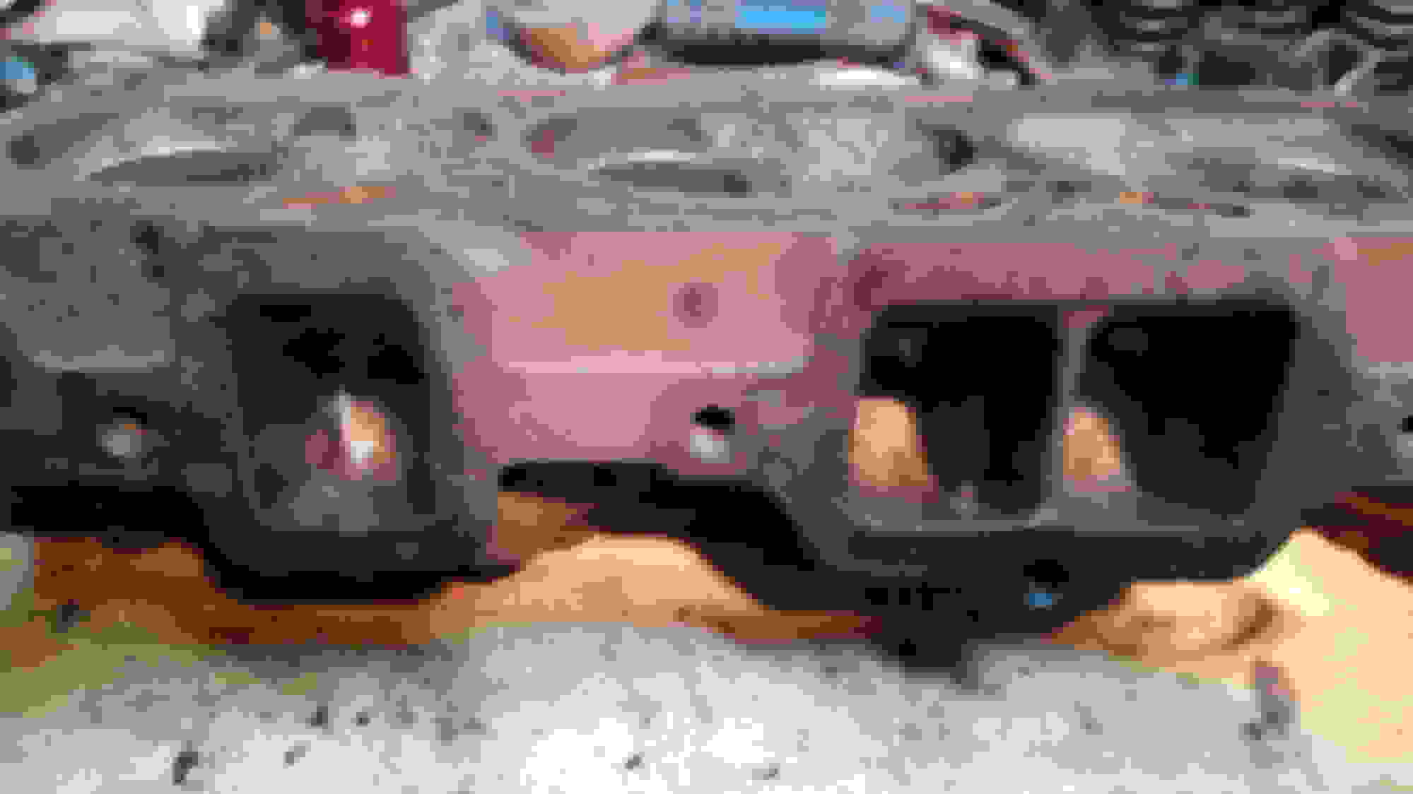
To start the guy in that website didn't quite know what he was doing, when he broke through into the water jacket is a good example of 'more is not always better'. You have to remember that air when flowing is like flowing water, it does not like to change directions and will bunch up slowing down the flow. Unlike water though air can expand and compress and in doing so this will change the flow characteristics. You want gradual changes especially at the valve pocket, the area from just below the valve seat to just in front of the valve guide area. The area that the guy broke through is like a wall in stead of a slope and he should never had hogged out that spot. He should have just removed the rough surface. Your head on the left is similar to or the same as his, also that is not tear dropped, it is a circle with a tail. What you really want and if there is enough material is a teardrop that would look like it is falling from the sky and not dripping off something. You can use the front of the teardrop to steer the air flow and the backside to steer & recombine the split airflow. If I had a choice I would use the head on the right because it has a better entry slope into the valve on the longside (sparkplug side), you can see it right by the valve guide. But this head will require more cutting and grinding than the head on the left which, I don't mind doing. It's all up to you whether you want to just clean up a set of heads or go for a big jump in airflow.
Well let's add to this thread. Getting ready to port my heads. I have a pair of 7a's and 8's. Differences on the intake side. I still have alot of reading to do before jumping right into porting.
I was reading about the tear drop around the guide. Is a related thread that says the guide bosses are narrowed but not tear dropped. In the related thread shows how the bosses are supposed to be tear dropped. If this other thread is right, the 8's I have already have the formation of the tear drop
Good eye I have never seen bare 7a and 8 heads. I cant remember anyone ever pointing out the difference in the casting.
If you look at ported heads the tear drop leading edge faces the port opening . It does look like the the 8 head has less shrouding compared to the 7a head. But with out testing its hard to say what head flows better as cast.
Thanks for posting
Last edited by Bernhard; Apr 20, 2019 at 08:36 AM.
I can't see the 8's flowing as well. In the valve pocket, the 8's have a wall then flows into the chamber.
The 7a's have a slight slope flowing into the chamber.
But with that said, would the 8's mix the air/fuel ratio better than the 7a's? Looks like the 7a's would ram the air/fuel into the chamber
To start the guy in that website didn't quite know what he was doing, when he broke through into the water jacket is a good example of 'more is not always better'. You have to remember that air when flowing is like flowing water, it does not like to change directions and will bunch up slowing down the flow. Unlike water though air can expand and compress and in doing so this will change the flow characteristics. You want gradual changes especially at the valve pocket, the area from just below the valve seat to just in front of the valve guide area. The area that the guy broke through is like a wall in stead of a slope and he should never had hogged out that spot. He should have just removed the rough surface. Your head on the left is similar to or the same as his, also that is not tear dropped, it is a circle with a tail. What you really want and if there is enough material is a teardrop that would look like it is falling from the sky and not dripping off something. You can use the front of the teardrop to steer the air flow and the backside to steer & recombine the split airflow. If I had a choice I would use the head on the right because it has a better entry slope into the valve on the longside (sparkplug side), you can see it right by the valve guide. But this head will require more cutting and grinding than the head on the left which, I don't mind doing. It's all up to you whether you want to just clean up a set of heads or go for a big jump in airflow.
Ray
If I use these 8's, what do I do with that little wall? Remove it totally or do a tear drop as well? So in sense would have a double tear drop. The tear drop effect I am aware of. Been researching into porting.
Thanks
I can't see the 8's flowing as well. In the valve pocket, the 8's have a wall then flows into the chamber.
The 7a's have a slight slope flowing into the chamber.
But with that said, would the 8's mix the air/fuel ratio better than the 7a's? Looks like the 7a's would ram the air/fuel into the chamber
Do you mean the lip under the exhaust valve? A bowl hog cutter or a grinder carefully will remove it. You can also polish the chamber to add CC to the 7A heads to lower compression a bit. With the bowls opened up the 8 should equal the 7A heads for flow.
Do you mean the lip under the exhaust valve? A bowl hog cutter or a grinder carefully will remove it. You can also polish the chamber to add CC to the 7A heads to lower compression a bit. With the bowls opened up the 8 should equal the 7A heads for flow.
I can't see the 8's flowing as well. In the valve pocket, the 8's have a wall then flows into the chamber.
The 7a's have a slight slope flowing into the chamber.
But with that said, would the 8's mix the air/fuel ratio better than the 7a's? Looks like the 7a's would ram the air/fuel into the chamber
Here is a link to some flow numbers for cylinder heads http://users.erols.com/srweiss/tablehdc.htm#Olds . You have to remember that Mid-Am had a habit of fudging the numbers a bit, also I believe they are gone now. Also I submitted my 'G' head flow numbers and when the guy posted them he recalculated the flow and posted lower numbers than what they actually flowed ^^. The 8's when cleaned up will flow better than the 7a's because of the transition to the valve seat on the short side radius and a slightly taller intake runner. The wall you mention on the 8's needs just a clean up and yes the air will bunch up there and create dead air but and a big BUT is this. If you get the runner length setup for ram-air effect then that bunched up dead air can be used when the valve just opens. I can calculated the correct intake runner length for you after the heads are ported. Air/fuel mixture happens in 2 area's, first in the intake runner with either making lateral scoring with the cutter or coarse sanding or if you want really good mixing then you add metal window screening across the intake gasket intake ports. This will give low rpm a torque boost and better cruising gas mileage but it hurts high rpm Hp above 3,500 rpm. Second for air/fuel mixing, Oldsmobile was way ahead of it's time when it came to swirl combustion, starting with the last generation heads for both small block & big block heads. I've wet flowed my buddies 'B' heads and my 'G' heads and they both create way too much swirl going into the cylinder for performance but, it makes for great torque and gas mileage. What is needed is to straighten out the flow which is very difficult unless you do wet flow testing to see what's going on. With the piston half way down the hole I got my 'G' heads to go from creating a swirl that went 7/8ths around the cylinder to half way around which is perfect for performance. The problem with this swirl is when you put a cam in with a lot of overlap you send a lot of air/fuel mixture right out the exhaust. You can even see the evidence when you do a plug check at the track, half of the ceramic porcelain will be completely wiped clean. I can't remember off hand which SBO heads were the best for mixing but the BBO head is the 'J' head, the smog head.
If I use these 8's, what do I do with that little wall? Remove it totally or do a tear drop as well? So in sense would have a double tear drop. The tear drop effect I am aware of. Been researching into porting.
Thanks
Can you be more specific about the wall so I know we're both on the same page?
Originally Posted by olds 307 and 403
Do you mean the lip under the exhaust valve? A bowl hog cutter or a grinder carefully will remove it. You can also polish the chamber to add CC to the 7A heads to lower compression a bit. With the bowls opened up the 8 should equal the 7A heads for flow.
At spot '1' you can see the factory plunge cut.Cutting the valve seats on raw castings is a two step process. First a plunge cut is done and second the valve seat is cut. So that remaining material can be removed by blending down to the port roof. When I say blending, I mean that unless you know the wall thickness then you create a sloping wall. You can remove material right up to the bottom of the valve seat for both the intake and exhaust.Preferably there should be no lip just a straight wall to the bottom of the seat. Please try not to hit the seat itself or the valve will have to sit to high for the stock valve train. At '2' on the 8 head, this area should just be smoothed out (polished) to the valve seat. At 3a & 3b you'll want to blend these into the valve seat. At '3b' is the area that causes most of the high swirl so you want to open this up but don't cut into the roof. Just leave about 1/16" or 0.065" of valve guide there and blend it down. See the picture below for a perfect teardrop on the intake & exhaust. Perfect is nice but the material needs to be there to do it, porting heads is always a compromise. Oh and yes polish the combustion chambers and exports ports to a mirror finish.
Thanks for the information 74sprint,
Ah you are from Winterpeg!?!?!?
The heads are having a total rebuild. punching them to 2.00/1.625.
Leaning more to the 8's tho. Went with flat tops, so going with 7a's will bring my ratio up too much.
Trying to keep to 9.5 to1
My first attempt at porting. So figure the easiest way to get used to it, start at the EGR bumps. Played for a couple hours.
74 sprint, see your teardrop coming from the intake, then cut along the back of the pocket wall. Is that something that should be done to these heads or try a tear drop that too?
To my thinking, if teardropped on the backside of the boss, that would create air velocity and force the air/fuel into the chamber
Does anyone know how many ounces or pounds of ZA-12 (zinc) is needed to fill heat riser passages for a set of BBO heads?
I did my #8's aluminum but so hard to tell how much used. Not very easy to pour and you lose pouring time quick, hence it cools. So melt way more than needed. I would say 2 coffee cups per head. But also saying this, you are better to do it in 2 pours per head. Fill most of the heatriser first going to the intake. Leave enough open so when you pour in the one port it fills the other side. The first pour i did, the aluminum sunk way too much. Wasnt happy with it at all. Removed the aluminum, I put the valves back and repeated the 2 part step. I poured way more this round, was a bit more work in the bowl but well worth it I think
Nice job filling those heads. Do you have the car running yet, does it change the exhaust note for the better?
Thank you. This is my first engine build, the power went way over what i thought it would do. Its kinda running, lol. She put out onnthe dyno a few weeks ago, now I need a transmissions and build the rear end
I wasn't able to make it to the pull, would of had them pull her to 6000.
From what I been told, filling the risers removes the pulses in those 2 chambers.
I wasn't able to make it to the pull, would of had them pull her to 6000.
From what I been told, filling the risers removes the pulses in those 2 chambers.
That�s way more power then I�d expect from a SBO. Unless it�s a stroker! The engine looks good.
That�s way more power then I�d expect from a SBO. Unless it�s a stroker! The engine looks good.
Yes way more than I thought too. She a 350 throughout, a build for my son on his last year of high school.
I do have a thread with the build in small block engines.
I had alot of help from Mark
Great build and hopefully you son has good friends and sense. That car will get him into trouble in a hurry, if he wants it🙂. I have set of filled #6 heads, 2"/1.625" valves and some port work. The exhaust ports look nice, I think the intake can use some work, won't know how much was done till I pull the valves. The guy I bought them from with 9.6 to 1 a .060" over 350 with a Comp 280H in a super heavy 74 Delta 88 ran 12.7's, can't be junk with those times and weight. Pics in the next couple of weeks.