When you click on links to various merchants on this site and make a purchase, this can result in this site earning a commission. Affiliate programs and affiliations include, but are not limited to, the eBay Partner Network.
Good news on the sending unit. I sprayed a little WD40 on the arm of the float and that seemed to do the trick. I tested with the ohm meter today, and the numbers went up and down with the float. I will try it one more time before it goes in the tank.
I picked back up on the rear bumper. The tape was a pain in the *** to remove, but I eventually got it all off. With the tape off, I could see where I need to make adjustments.
I figured I would start connecting the light connectors. Nothing in the back is working with the exception of the trunk light. The rear side markers aren�t even working. I assume it is a grounding issue. I changed out the fuses but that didn�t do the trick. I know they worked prior to tear down because it was one of the few lights I actually tested. The tiny ground wire to the passenger side of the trunk latch receiver is tight and I scratched away the paint under it. Could it be a result of powdercoated bumper brackets?
Here is the factory sending unit and the NOS unit. The reproduction unit has the sock on the opposite side. The factory ground wire, as well as the NOS wire are brown whereas the aftermarket sending unit has a black wire.
Cleaned the factory rubber ring that was on the old sending unit.
This is the foam destructor I need.
Testing lights in the bubble. Frustrating that the rears aren�t working.
No question that the powder coated bumper brackets are at least part of the problem. On Rallye 350's they had to add a ground strap to the back bumper because of the urethane bumper coating. Powder coat is really bad for the grounding situation on older cars that don't have a common ground plate that everything runs back to, You will either need to add a ground wire or take the brackets off and clean the power coat off the bolt areas of the bracket and the frame.
To test it, Just put a jumper wire from a good ground to the tail light housing.
Thanks for all the advice on the bumper. Al and Eric were spot on—grounding is the issue. (No surprise!) I knew I at least had power going to the back because the trunk light was working. I disconnected the rear harness for the back and it tested okay with my light tester. I tried an alligator clip from the chrome near the housing (chrome not visible with the TL’s installed) and the other end of the clip to an exhaust hanger bolt. Nothing. I added another alligator clip to the chrome and the other end to another hanger bolt. The bumper lights lit up like a Christmas tree! Phew! I even tested the backup lights by putting the shifter in reverse and slowly moving the column lever down a bit.
So, I have at least narrowed the issue to grounding. I don’t really want to remove the bumper and redo the brackets. I am going to try and scuff the metal on the brackets and dremmel around the bolt holes for the bumper bolts, as well as the brackets, and see if that does the trick. Worst case, the bumper comes off and I strip the brackets.
The strange part to all of this is that the rear side markers still aren’t working. I pulled a bulb and was able to get the light tester to illuminate. Hmm. I guess it’s possible I received a bad batch of bulbs? I need to try different bulbs. I think the rear side markers have a ground wire so not sure it’s a ground issue. Thoughts?
The initial added alligator clip ground did nothing. When I added a second wire, I was then able to get the lights on.
I’m actually surprised the old NOS bulbs worked!
Illuminating the restored AD Pelunis plate frame.
Reverse lights, check!
Last edited by WTHIRTY1; June 1st, 2021 at 09:43 AM.
You "should" be able to just remove one bolt at a time and clean the paint and powder off like you mentioned. I would use just a little Super Lube under the heads of the bolts and under the washers. Any that squeezes out after tightening, just wipe it off. Just remember that the powder is also between the bumper and the brackets also. May have to remove the powder on those bolts as well. On those, you may be able to just slip a star washer between the bumper and bracket for each bolt. Not sure if the star washer would dig deep enough to penetrate the powder or not.
I ended up taking the back bumper off to get the brackets removed. This week I will strip the thick
powder and respray them. I tried using a dremmel where I needed the contact but it didn�t net the result I was looking for. The right thing to do is just redo the brackets.
As a follow up to the rear side marker lights not working, it turns out the box of bulbs from Wagner were all bad. Go figure. Tested the new bulbs, popped them in, and we are set. A few minor setbacks, but once the brackets are stripped and painted, I should be back in business.
While the bumper is off, I am going to install the gas tank. I should have much better access for the crimp clamp pliers with the bumper off. I wanted to get the stencil painted on the underside but in a less conspicuous area than most do during their restos. The �easy� spot on the tank is the flat part for the stencil, however, I opted to put it in a corner and under one of the tank straps. The weather should be in the 80�s this week so I�ll spray on Tuesday.
I tried getting better contact by using a file and the dremmel but figured it was easier to just remove the bumper and redo the brackets.
Tank stencil. Wrapping it around the curves was a treat.
Tonight was all about gas tank prep. The tank itself is a Spectra. The sending unit is an NOS piece that I tested thoroughly to ensure it would work. The wire for the sending unit is original to the car.
I used the tank stencil from Cornea and replicated the exact position of the marking on the sheet metal. I took creative liberty and also put the stencil on the underside of the tank to recreate the marking. I used a black grease pencil to recreate the ‘37’ that was on the factory tank. As noted in previous posts, that number ‘37’ is visible on the inside of the glove box, underside of the fuse panel, on the axle cover, and the RH front frame rail.
I used detailed photos from the tear down to recreate the tape placement and routing of the wire. I wanted to get the perforated edge like the factory on the masking tape so I used a dispenser.
Finally, I mounted the two hoses and tank vent. I restored a clamp in red, as well as a clamp in white, as the one I removed for the larger hose was white. I should be installing the tank this weekend.
Original tank.
Factory tape placement.
Grease markings and mice debris.
More tape.
Recreation of the sheet metal markings.
An attempt at putting the tape in a similar place as the factory.
Recreation of the ‘37’ grease pencil marking.
NOS sending unit and factory wire.
Ordered the butcher tape and dispenser from Amazon.
Last edited by WTHIRTY1; June 1st, 2021 at 09:43 AM.
This morning was all about tank installation. I put the two short bolts in at the rear of the car to get the straps in place. I already had the tank basically under the rear of the car, so once the straps were in place, I fed the neck of the tank up over the frame and had my Dad pull the tank neck in place. In tandem, we used a floor jack with a wrapped piece of wood under the tank. The NOS straps needed some serious massaging. Once the tank was in place, I pulled the straps towards the rear and installed the long bolts. I ended up using the air ratchet with a really long extension to make it easier, and I’m glad I did.
A few notes for those doing this.
Put your hoses on the ending unit and attach to the lines in the frame when the tank is in place. My factory clamps were pointed upwards on the sending unit so I am assuming that is how the factory did it...not sure how else they would have accesses those clamps. The clamps to the frame lines were easy access.
I didn’t have a ton of real estate to work with, but I did jack the car up and on to stands for an extra 6-8”. I wanted the straps to “crimp together” at the rear so once the tank was in place and secure, I backed off one strap, used channel locks to crimp the strap, and then reinstalled the short bolt. This made a difference. It also helped get any creases out of the strap.
Pay close attention to the routing of the tan wire. I had a piece of tape on the neck as well so I added a piece of masking tape during the install.
Factory hose clamps.
Sending unit ground wire.
I mounted the vent bracket before the tank install. I found it easier to slide the hoses up and then connect the vent to the hoses from the top.
Factory positioning on the cap. The bracket for the tank neck to the frame took a bit of massaging.
Last edited by WTHIRTY1; June 1st, 2021 at 09:42 AM.
I see your brake pedal bushings are looking a bit worn if my eyes aren't deceiving me. Is it that you want to reuse them or not wanting a newer part number? I believe it's 379256. 5/8". If it is, here's some white NOS "white" ones along with a few translucent ones, as a lot. https://www.ebay.com/itm/NOS-1962-19...MAAOSwiuFep2Fy
If not, no big deal. Was just wondering. The new ones may be a bit brittle anyway for their age.
Love the work and the detailed pictures
This Thread and the 69 442 restoration by 69442C, https://classicoldsmobile.com/forums...project-51363/
are the two best Documented restorations on CO, IMO
I applaud your efforts and hope to see the car in person some time when complete.
Jimmy, your replicating markings on the "top" of your gas tank ? That's insane, along with the rest of this build. I applaud your insanity !
I have always said that it is what you don't see that makes or brakes a restoration. If you ever have the chance, pull the back ash trays out of a supposed high quality restoration and shine a light in there. If it looks like new in there also then they likely didn't take any shortcuts.
I don't know why the Spectra tanks don't have the cap on the fill neck soldered on correct. I had to unsolder mine and solder it back on in the correct position. Was your clocked right from them? Maybe you said above, I did not read all of it yet
I don't know why the Spectra tanks don't have the cap on the fill neck soldered on correct. I had to unsolder mine and solder it back on in the correct position. Was your clocked right from them? Maybe you said above, I did not read all of it yet
Eric, I had my radiator shop resolder the end part of the neck so the cap would sit properly when sealed.
Originally Posted by Schne442
Love the work and the detailed pictures
This Thread and the 69 442 restoration by 69442C, https://classicoldsmobile.com/forums...project-51363/
are the two best Documented restorations on CO, IMO
I applaud your efforts and hope to see the car in person some time when complete.
Thanks for sharing, and I appreciate the compliment. That is a great thread with an emotional ending.
Originally Posted by Vader
Jimmy, your replicating markings on the "top" of your gas tank ? That's insane, along with the rest of this build. I applaud your insanity !
Thanks, Mike! Hopefully, the insanity is coming to an end soon.
On Friday, we left Chicago around 5:30 am local time for the four hour drive to Carshine in Jackson, MI. We cruised at about 70 mph, and we could tell a noticeable difference in the weight since the car is nearly at its full weight. My good friend Casey Marks was kind enough to shoot over from his place in Michigan to help unload and check the car out.
There are just a few items that Bob and Carlos will take care of, and then we should have a quick turnaround to get the car back to Chicago. I must say, the winch inside the trailer has been a lifesaver! I cannot wait until I can just drive the car in and out of the trailer…hopefully soon!
Meanwhile, I have a few loose ends I am tying up back home over the next week or two so I can do a final thrash when the car is home.
The original rear LH moulding has a chunk of it missing. I suspect this was from the steel mud flaps that were in place for years. The NOS moulding needs to go to the polisher.
The powder ended up being a pain to blast on the rear bumper brackets. They are now being chemically stripped, and then the brackets will be blasted. I hope to get those refinished this week providing the weather warms up.
I haven’t touched the driveshaft, yet. I need to start by popping out the u-joints, and then I’ll pour the evaporust in to the PVC. It is going to need some filler since the pitting is a bit much.
The factory rear drums were blasted and painted. I need to find a shop that will turn the insides. Anyone have a local recommendation?
The NOS tires need a bath. I’m going to carefully use the Flex with the bristle brush on the sidewalls ever so lightly. I don't want to mess up any of the markings on the tread portion of the rubber.
As you can see, there is still a ton of stuff to get through!
Walking through the final “punch list.”
From left to right. My Dad (Jim), Carlos (Carshine), Bob (Carshine), Me, and Casey Marks (engine builder).
Another shot of the support team / therapy group.
Last edited by WTHIRTY1; May 9th, 2021 at 09:59 AM.
One more quick update. The W-31 came with a dealer installed alarm, per the paperwork from AD Pelunis. Most of the alarm had already been ripped out of the car by the time I took possession of the car with the exception of the jamb holes and trunk switch / wiring. A friend recently shared pictures of a documented ‘70 442 with a dealer installed alarm, and the switches were identical to the ones on the 31. My car had holes drilled in to the passenger side inner fender that I couldn’t figure out what they were from. While comparing the holes in the 442 to the holes I had, and while examining the siren bracket, I am certain I have identified the alarm system that was in my car. There are NOS units available so I have one being delivered. The alarm was made by a company called Jubilee. Not sure I will wire it all up, but I can at least dummy some of it up since I left all the dealer installed holes. I won’t be drilling a hole in the fender, though! I can't imagine there were several car alarms available in 1970, I have seen the Corvette alarms, and it uses an actual GM key, whereas the original owner of the car described the key that matches this alarm kit to perfection.
Anyone familiar with these? Looks like Sears carried them.
Last edited by WTHIRTY1; May 9th, 2021 at 09:55 AM.
Finished stripping the rear bumper brackets down to bare metal. I can see where the washers dug in to the brackets so I’ll use that as an aide when I install the bumper. The plan is to paint the brackets this weekend and hopefully put the bumper back on next weekend providing the car is ready for pickup.
Last edited by WTHIRTY1; June 1st, 2021 at 09:41 AM.
The minor adjustments Bob and Carshine were taking care of are complete. The plan is to head up to Michigan on Tuesday and bring the car home.
The rear bumper brackets are complete. I sprayed them a chassis black, and hopefully the ground issues for the back bumper will be behind me (pun intended).
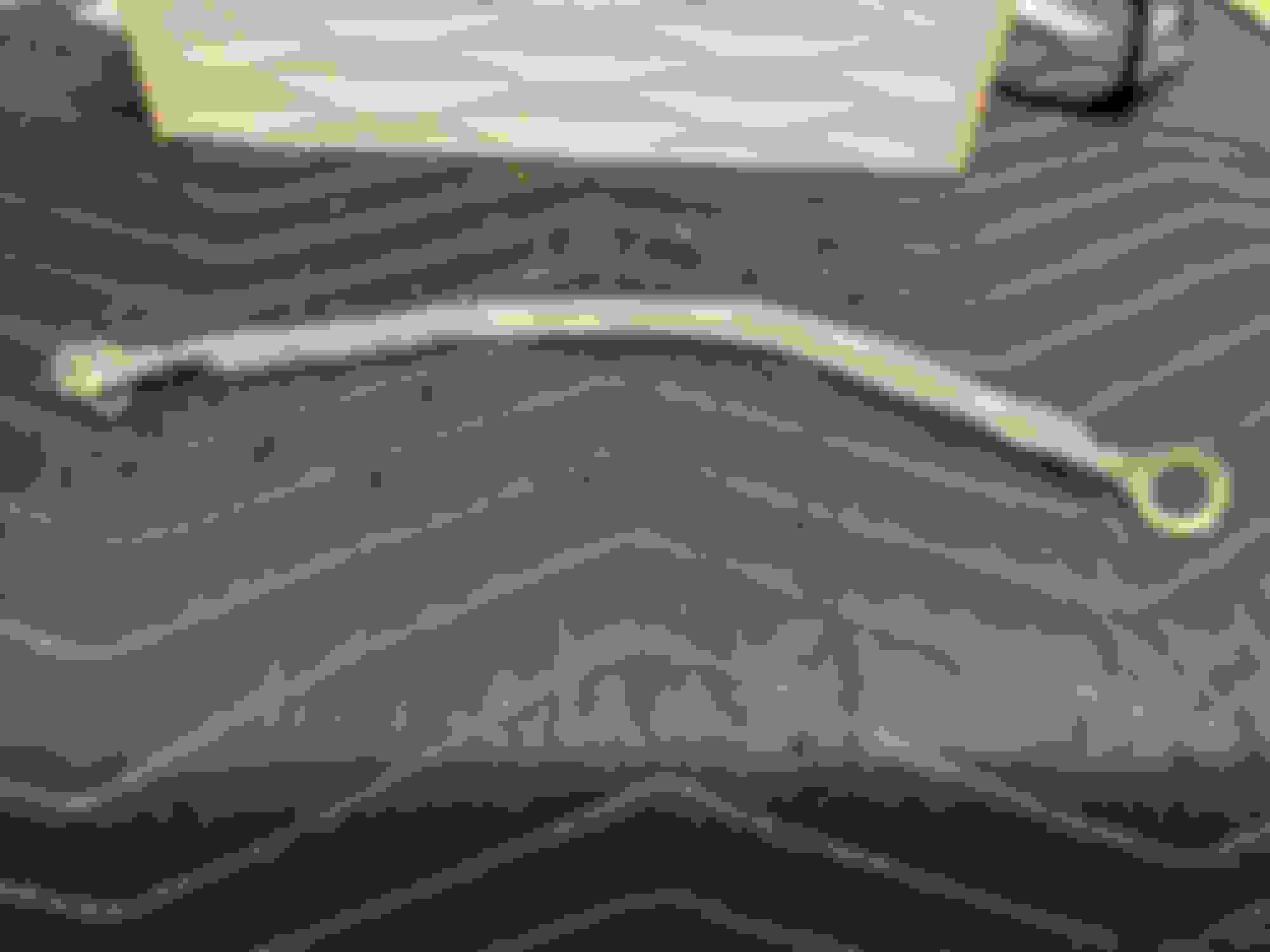
Some may remember the 4” PVC pipe I used to make an Evaporust bath for the driveshaft. I finally filled it with Evaporust and let the driveshaft soak for 48 hours. My intent was to hopefully find the factory stripes, assuming that this is actually the factory driveshaft, and I think I lucked out. When I pulled the driveshaft out, I could see two distinct areas with lines. Those areas were in much better condition than the rest of the shaft and the pitting was marginal compared to the rest of the part. I have seen examples of W-car driveshafts where the stripes were much closer. In my example, the first stripe is approximately 21 1/2” back and almost 1” thick. The next stripe started around 37 1/2” and about 1 1/4” wide. I have included a reference picture for those to see the starting point of my measurements. Next, I will remove the u-joints and strip the shaft for body work.
I know there are some that have documented the first stripe around 17 1/2”, however, I believe those are for stick 31’s. I took a closer look around that 17 1/2” area and didn’t see anything. The pitting is also consistent with the rest of the shaft sans the stripes I documented above.
Starting measurement spot.
Location of the first stripe.
Location of the second stripe.
Second stripe again.
Right out of the pipe of Evaporust.
Last edited by WTHIRTY1; June 1st, 2021 at 09:40 AM.
Picked up the car from Bob and Carlos at Carshine yesterday. I am really pleased with the final product!
One of the additional items I had asked Bob to tackle was matching the plastics for the lap belts and shoulder harness retainers. I didn’t like the color Python used so Bob created a perfect match for the dark blue that matches the kick panels.
Now that the car is home, I want to push to get everything finished in the next two weeks. Getting the car up on the lift for a day or two will really help.
Freshly polished and ready to go.
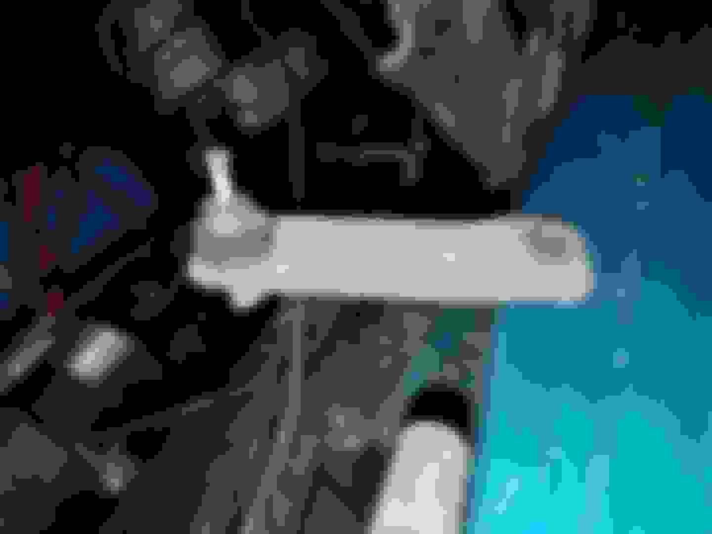
Public Service Announcement: the reproduction rear spiral shocks are garbage. Zooming in on the picture below will show a crack in the weld between the pieces. Be careful!
Last edited by WTHIRTY1; June 1st, 2021 at 09:40 AM.
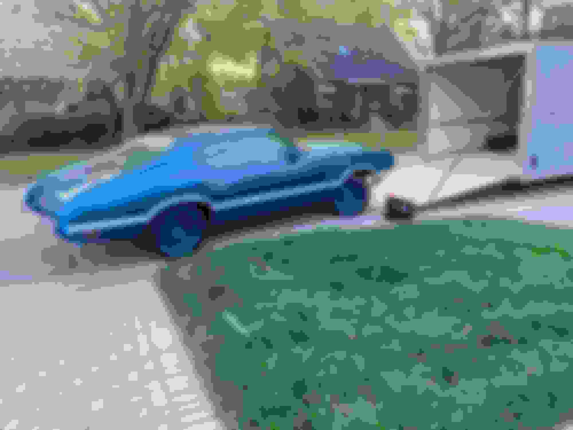
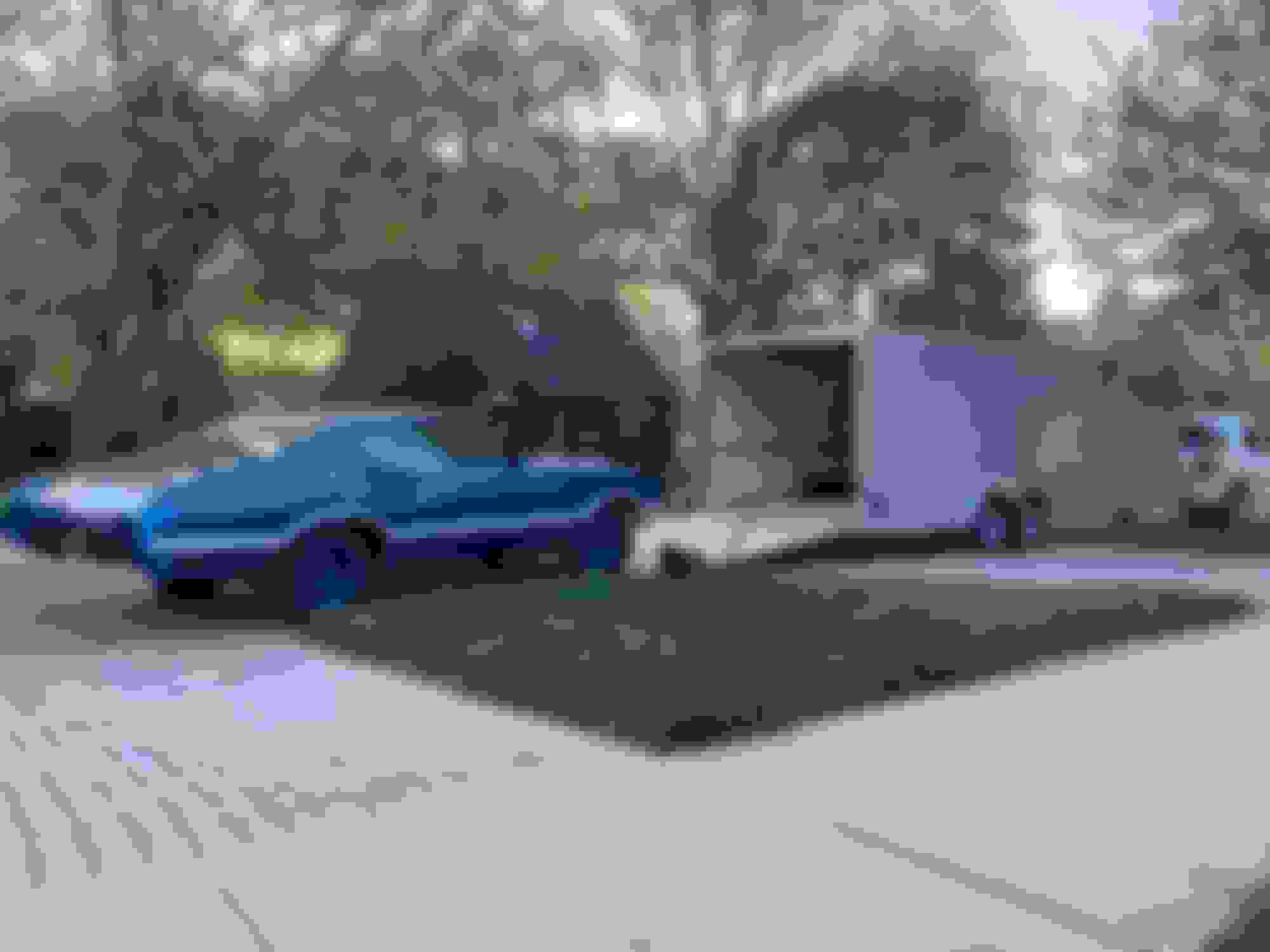
Unloaded the car yesterday and pushed it in to the garage. The paint looks outstanding with the recent polish!
The thing that is killing me right now is the way the front end is sitting. It�s just too high. I�m good with how the back is sitting. The front springs are the original factory ones that came on the car. In fact, they even had the tags on them when I removed them. The pigtails are positioned in the slot on the lower arms, per the chassis manual. I believe the top part of the springs are seated in the frame properly, and if they weren�t, I suspect 1000+ miles in the trailer would have bounced them in to place. The suspension hasn�t been torqued but it is tight. Could that be in? Bushings are all NOS so maybe the rubber is too hard? Would a front end alignment help things settle? It may come down a touch with the front bumper and fluids but hard to say. I haven�t tried bouncing it yet. Looking for input.
Not sure that I have your answer but I love your car.
How much more weight is the bumper and brackets etc? Maybe you need to get the weight on there and drive it. Give it a few tight lefts and rights to seat things.
The thing that is killing me right now is the way the front end is sitting. It�s just too high. The suspension hasn�t been torqued but it is tight.
The consensus is that the control arms will not be torqued until the weight is on the car and the car is at the right height. Perhaps the control arms are tighter than you realize yielding a
height that is undesirable.
Also, if the area on the inside of the control housing was not lubricated prior to installing the control arm into the housing this can cause stiffness along with a premature torque of the bolts.
If it were me, I�d loosen the control arms at this time and bounce the car to see if that helps. What can it hurt?
Here is a good video that explains what I�m talking about. Hope this helps!
The bumper will not add enough weight to make a difference. I had a similar problem with mine when I put the front end together after rebuilding. You absolutely have to make sure the upper and lower control arms are NOT torqued until the car is sitting with its weight on the suspension. If the suspension feels tight, I would say there is an issue with the control arms binding.
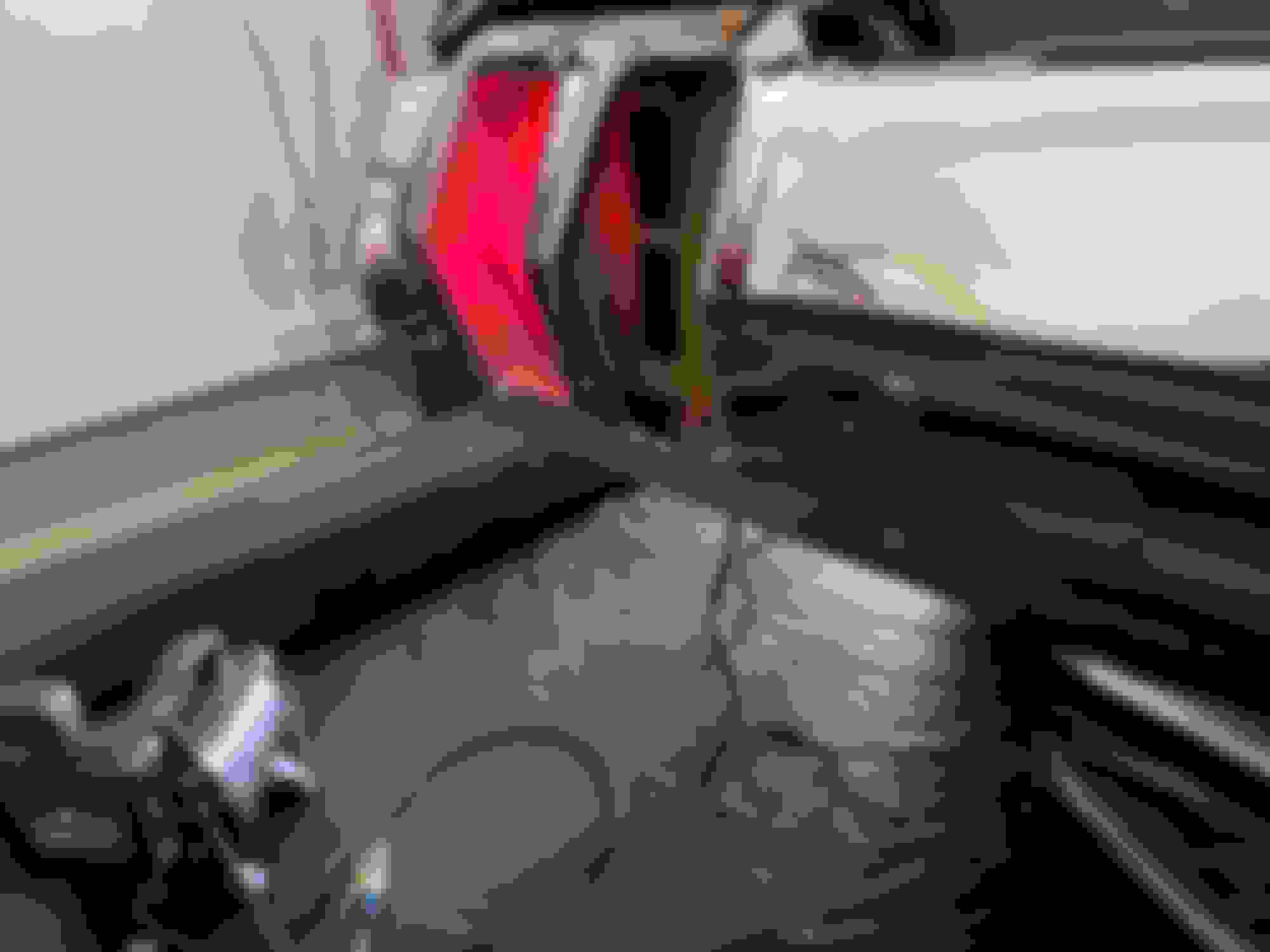
With the rear bumper brackets recently stripped, blasted, and repainted I charged ahead and reinstalled the bumper last night. The same crew consisting of my Dad and wife helped put the bumper in to position while I adjusted and tightened. I think in terms of positioning it is really close, and time permitting, I will make a few subtle adjustments. Wired everything up and no issues with grounding. Phew.
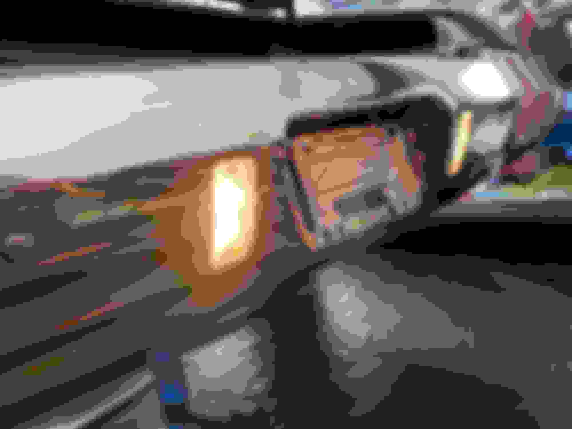
Additionally, this is also the first time I have connected power since installing the tank. I was nervous the NOS sending unit would give me fits, but as soon as I turned the key, I saw the fuel gauge slowly go all the way to the left and stop right on �E�. Awesome.
Bumper back on.
Fuel gauge appears to be working as does the sending unit.
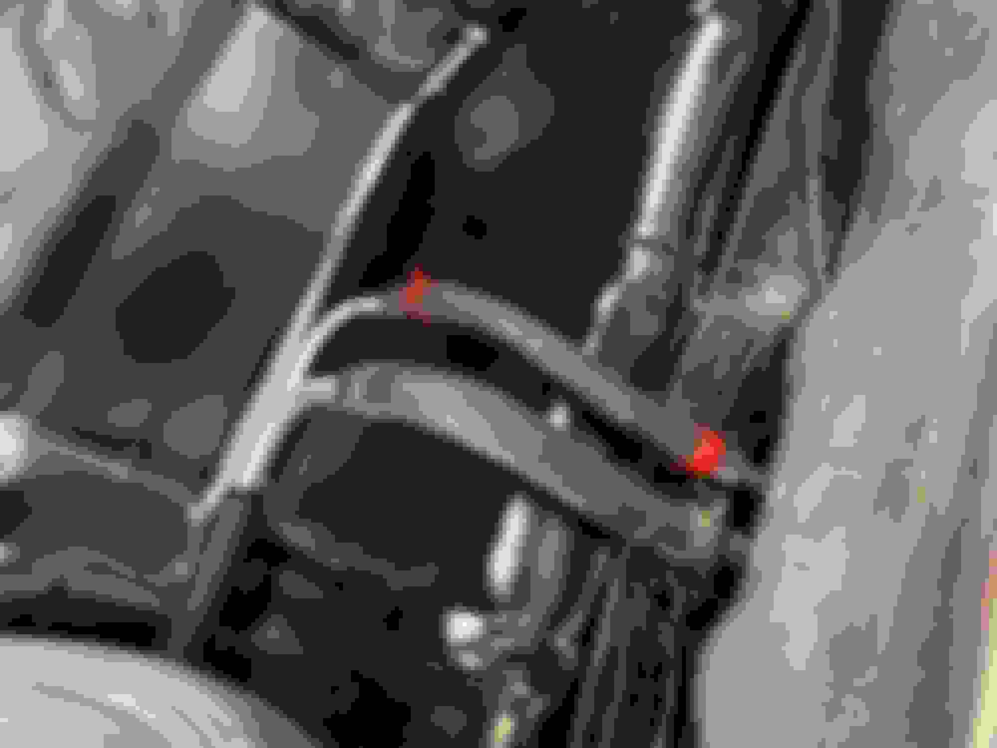
Peek-a-boo. The tan wire has crazy routing where it goes to the black clip on the RH side and then back across to the hole in the floor on the LH side. I was able to save my original black clip so that I what I reused. Note the gas cap positioning when sealed and the galvanized finish on the door.
Last edited by WTHIRTY1; May 25th, 2021 at 05:38 AM.
Based on measurements from a few survivor cars, plus the published measurements that are available, it appears the front end is almost 2.5� to 3� too high.
I loosened the four big nuts on the upper arm cross shafts, loosened the nuts on the four bolts that hold the lower control arms in place, and then shook the front end as much as I could. Still nothing. I went underneath with the camera, and it appears the pigtails are where they need to be, per the PIM and Chassis Manual, with the pigtail end visible through the tiny hole of the lower arm. I still need to get the telescopic camera out to see how the springs are seated inside the frame, but I recall getting them in there properly when I had the spring compressor attached. These are the factory born with springs to this car, and they even had the correct part number tags still affixed to them when I disassembled. I know the ride height prior to disassembly was near perfect.
The things that have changed are the arms themselves (off a rust free car), all new NOS Harris bushings, NOS ball joints at the top and reproduction ball joints at the bottom, the rubber bumpers under the upper arms are the originals, and the original spindles and steering arms were also reused. I haven�t taken a torque wrench to anything, however, I did have the bolts in the suspension tightened with a 1/2 turn of the ratchet. Could the shocks be causing the issue? I would have thought 50 year old shocks would have been garbage to begin with, but maybe instead of leaking they�re seized?
I may see if I can loosen the arms up a bit more. I might even try spraying some graphite between the lower arms and the frame to see if that might help. Outside of all that, I am at a loss.
From the ground to the stainless I am about 29 1/8�.
My friend�s non a/c survivor Rallye is at 26 1/4�.
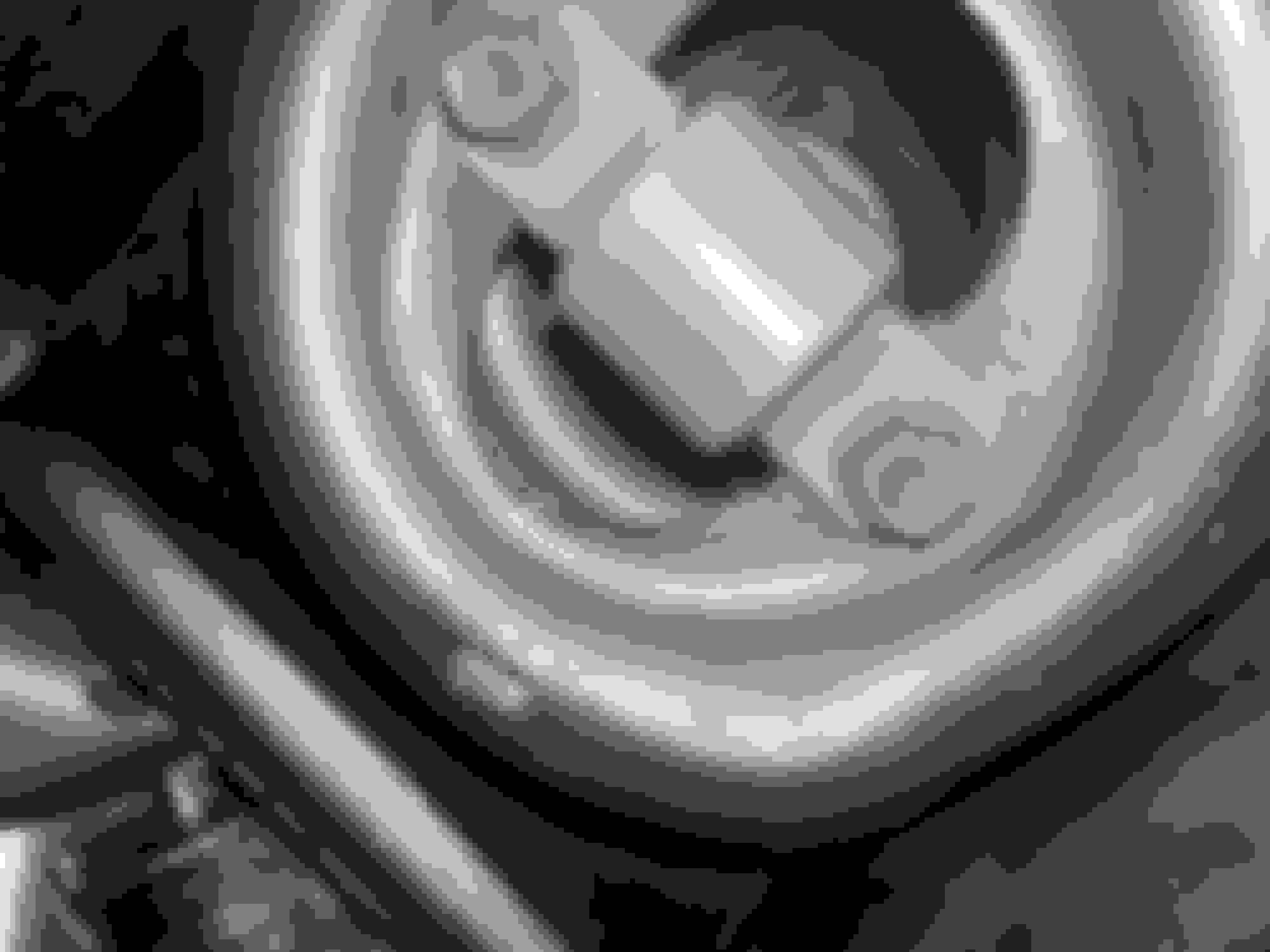
Here is the pigtail on the RH side. Does that look
right?
LH side.
LH lower arm.
It looks like the upper arm has room to move.
Last edited by WTHIRTY1; May 25th, 2021 at 06:31 AM.
Thanks for the replies. This is what I was afraid of. Is there a way to shift them in to place without having to tear everything apart?
If they are in wrong at the top you will have to pop the ball joints and take the springs loose. Been a while but I think there is a plate that the spring can be put on the wrong side of but not sure. I done the same thing one time and can't visualize now how it looked in there.
There are ride height measurements in assembly manuals and they measure from the rockers, which is a good way to stay consistent in "what do I measure for ride height?" methods.
3� is a large amount of difference if those are the original springs. I find it difficult to imagine the springs could be that far off and not look really off to create that large of a difference by themselves. I know you want to get it right for your first show but if it was me I would wait on popping the ball joints and repositioning until I cycled the suspension a bunch on the road and got the front aligned. Quick story. I had a Chevy truck that I rebuilt the front suspension on and got it all assembled and and then went for a ride, and I heard a loud pop when driving. Checked everything and all looked good. All I could think is that the spring was not quite seated and shifted to its happy place. That was 20 yrs ago and the truck is still good! I know that�s not a good way to get a spring in the right place but I don�t think it�s going anywhere. I�d hate for you to pull the ball joints apart until you give everything a try.
There are ride height measurements in assembly manuals and they measure from the rockers, which is a good way to stay consistent in "what do I measure for ride height?" methods.
Correct, that is one area of measurement. I am also using the AMA specs from 1969 to measure.
I'm curious how the springs could be in the proper position on the lower arm but not in the perch at the top (rotated - not off center)? The phots showing the ends of the pigtails in the 'windows' looks good to me. I put springs (Moog) on one of my cars last year and don't remember if there was a R and L. That seems like the only possibility for something to be wrong. The orientation of the pigtail stops take 'reasonable' offset/misalignment into consideration. They're not that sensitive. Seems like the only way for the top to be off if the bottom is good is if there's a R and L and the 'end pigtail' is in a different clocked position than the 'start pigtail' on each.
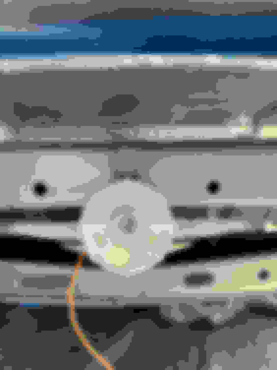
Good news and not so good news. I used the telescopic camera to see the top of the springs,
and they are definitely not in their perch. I am hoping that with the spring compressor we have, I can drop the shocks, compress the spring, and put it in to place. We’ll see.
I have a two page punch list that I am working off of right now. Knocked out the engine ground and vacuum tee installation as well as the hood light last night. The hood light has an interesting routing of the wires so pay close attention to the diagram in the PIM. Inside the car, I had to redo the LH visor bushing as it wasn’t staying in position.
I found a local shop that had a lathe for the rear drums so I will be picking those back up today. I also had them punch out the u-joints so I can get started on the driveshaft restoration.
Long way to go in the next 5 weeks, but I am going to give it a try and see if we can’t get the car done for Auburn!
Missed perch in the frame for the springs. I suspect that is my ride height issue.
Replated bolt and lock / star washer fit engine ground.
Replated the round ends of the ground strap clear zinc. Cleaned the braided portion of the strap with Eastwood’s paint prep.
Last edited by WTHIRTY1; June 1st, 2021 at 09:39 AM.
 April 22nd, 2021, 08:25 PM