When you click on links to various merchants on this site and make a purchase, this can result in this site earning a commission. Affiliate programs and affiliations include, but are not limited to, the eBay Partner Network.
Just wondering, at this point in your study, have you determined how the turn signal is cancelled? I know you suspect that the little pins on the back of the horn ring are responsible for the cancelling feature, but any thoughts on what they may actuate?
I know, I know......as if you haven't done enough already!
Preparing for reassembly
Use the CSM diagram & these pictures for reference. They should make the job easier. I have a velcro-mounted old iPad on my garage cabinet door to display diagrams & play music in the garage. I just look up and there's an exploded view. The CSM is just as good.
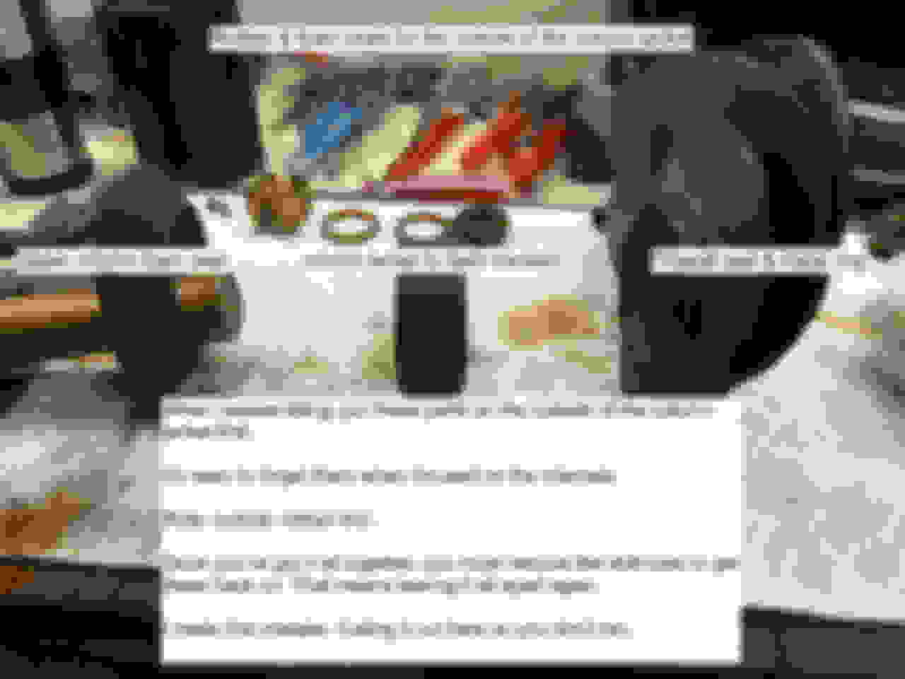
Organize your parts into assemblies in order from column-top to column-bottom on a clean sheet of paper towel. There are a lot of parts. I needed 4 paper towel sheets.
Consider organizing parts on a dedicated folding table you can walk away from & return to. If you're not thrashing from start to finish have a sharpie & some sticky notes or paper to remind yourself of next steps.
It helps to organize your tools too. If you know a particular socket or wrench is associated with just one part of the column put it near those parts.
Keep the some spray oil, a grease pot & some q-tips nearby to paint grease on whatever you forgot to grease in servicing.
It helps to have a box of disposable gloves to keep your hands as clean as you need them to be when handling intentionally greasy parts, or to grab a fresh pair to handle trim or other non-greasy parts.
I used to be a technical teacher, so yeah, this may be a course...
The pins on the back of the horn ring knock back some metal springs on the upper turn signal in their rotational travel to cancel the turn signal. Simple, effective design, unless one or both of your horn ring pins are broken. The big difference between the 1966 and what little I know of later years is that they went from 2 to 1 cancellation pin either in 1967 or shortly thereafter as GM was simplifying these things.
I have a spare horn ring or 2, but I think I recall throwing away a couple that had broken pins.
Cheers
Chris
Thanks for that. So the pins must be able to slip past those rings on the springs when you turn the wheel yet hook them on the way back to cancel (I guess?). Mine do not always cancel consistently. I'd say that 50% of the time, they cancel properly. This thread has definitely got me thinking that it might just be an adjustment. Will be interesting to look at it when I get some time, armed with all this knowledge you have most graciously given us.
Reassembly: The Column (re) Awakens
So you've got all your parts cleaned & organized and you have a couple of hours to put the column back together. I don't recall what I devoted to my first run through on just reassembly, but it had to be 4-6 hours. Hopefully you're smarter than me & can do this in less time. And maybe this guide will help...
Put on your disposable gloves. We're gonna get greasy. Then clean. Then greasy again.
It's gonna sound weird, but start with the outside of the column. There are 3 foam and rubber parts that the CSM diagrams don't call out and if you miss them, you'll need to pull the whole thing apart again just to install what seem to be trivial parts. But they're not. You can arguably leave off the foam ring which protects the upper column parts, accepting that yeah, more cabin dirt will get in there.
You cannot leave the rubber ring off the column jacket dash mount because if you do, you'll ground the column to the dash and get a constant horn. Then you'll figure out what you have to do to fix it and start driving something else. In a pinch you can slice a bike inner tube and use that, but isn't it best to just get it right from the outset?
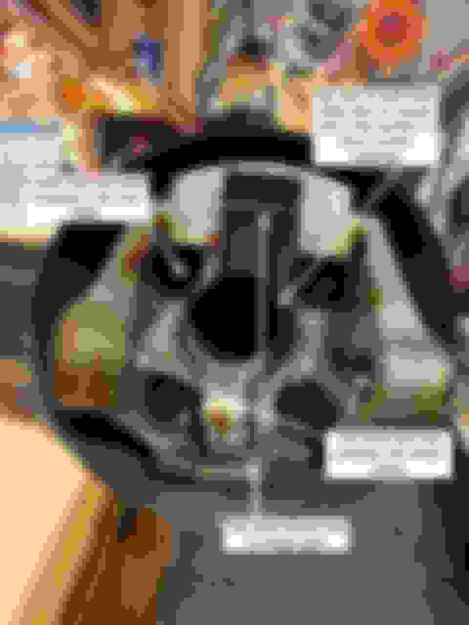
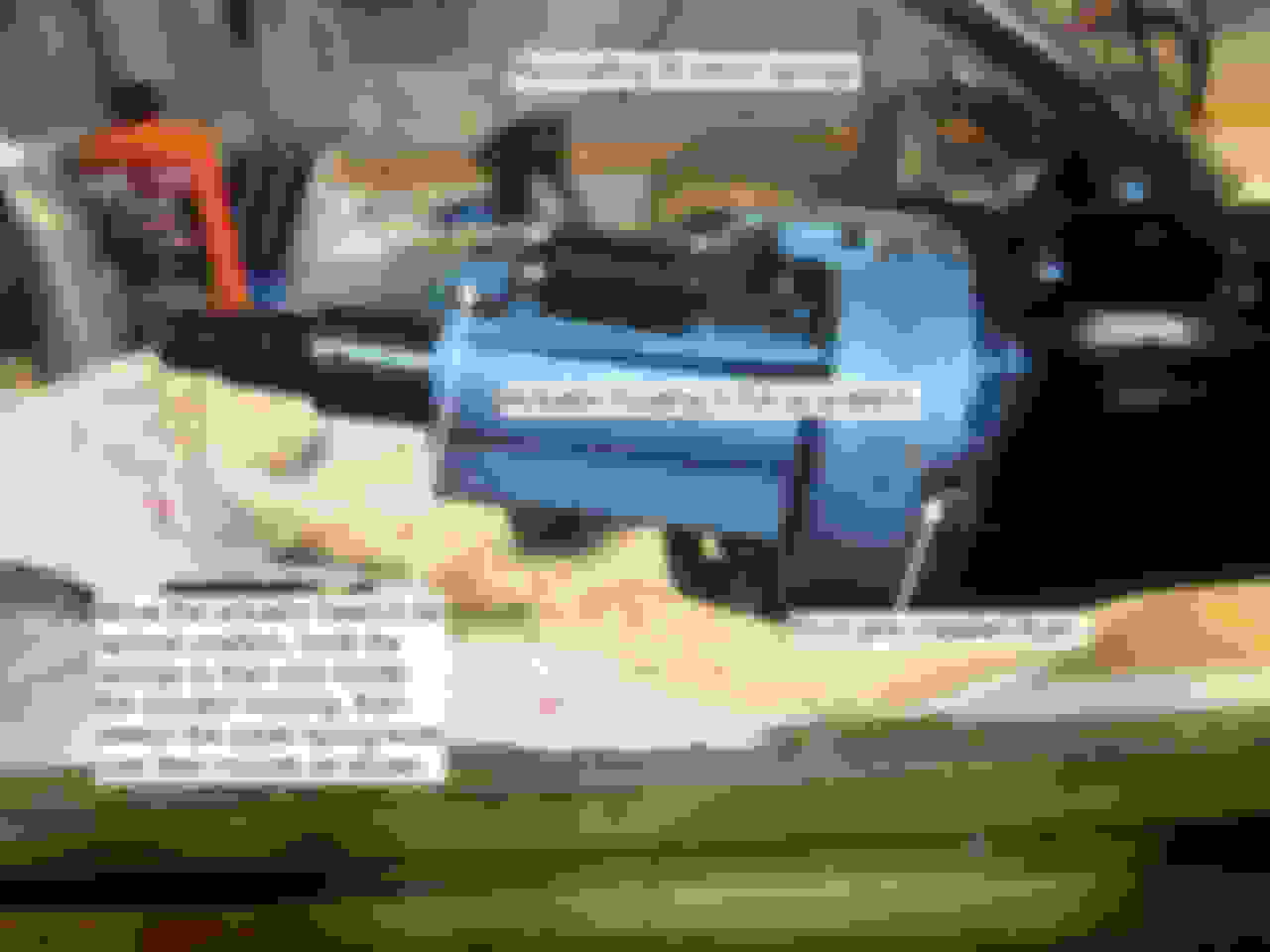
Finally there's the firewall mounting plate/gasket. If you leave that off you'll have natural air conditioning, bugs and other stuff blowing up at you from the engine. Here's a shot of how to get the external parts right before you forget: Put these on before you start on the internals.
Here's what these parts look like on the column. Note that this column is clocked vertical as shown by the slot: Locating foam & rubber parts on column jacket
So now your column jacket is in in the vise mounted horizontally with the top on the left and the bottom on the right. Let's start putting parts back in. We're going to do this in a sort of reverse-concentric order going from the outer rings to to the inner rings.
Shift Tube
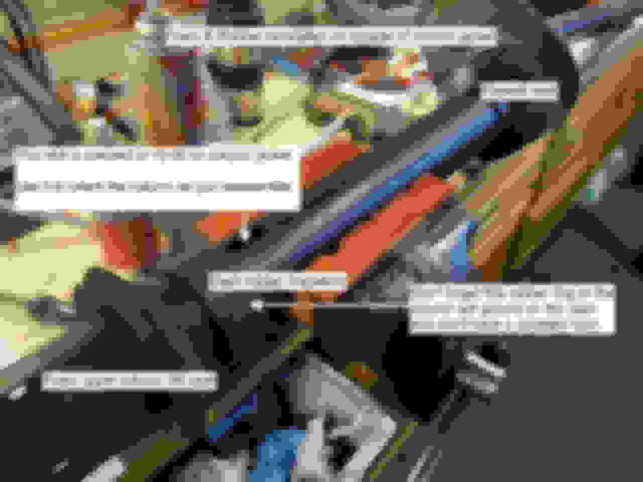
The first part to go back in is the shift tube. It seems simple but it has to mate, clocked to the shift bowl and along the way you have to stick on the wave washer and lock plate, nudge those into place, then nudge the tube up further to secure the thrust washer and retaining ring. All this has to be done with the transmission connection clocked in the lower slot in "Low" gear position so it can slide back & forth as you clock it & seat it in the lock plate.
Before we reinstall the shift tube, let's take a moment for the long-rotted-out foam seal that protects the lower column from engine dirt. It disintegrated, but kept dirt out of the lower column sitting behind the lower bearing adaptor ring. I replaced mine with a rubber washer like this. Use a rubber washer to replace the disintegrated lower column foam seal or live with engine dirt and possibly water in your lower column. If it's the outer diameter is too large it may inhibit shifter smoothness.
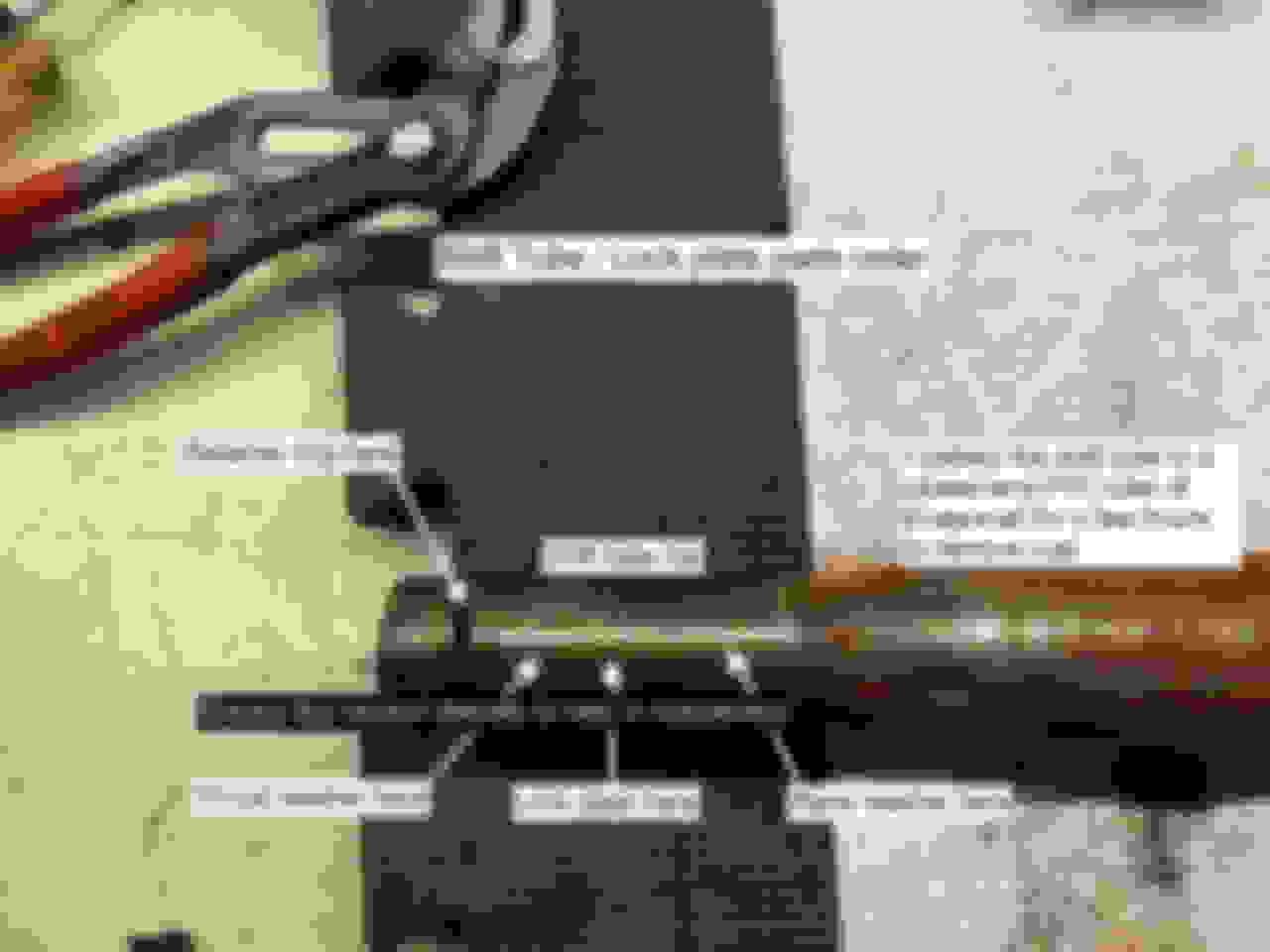
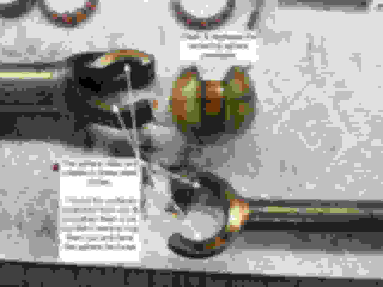
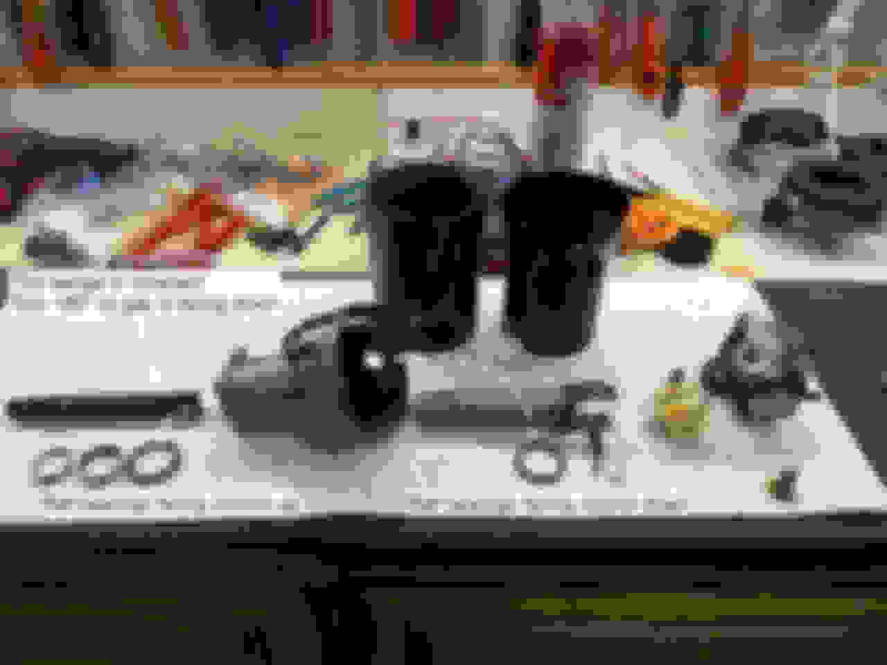
Here are the parts: Left = column top, right= column bottom, but it's a bit of trial and error to slip the shift tube up into the lock plate.
On the column here's what you're supposed to do. Grease the top of the shift tube well so you can slip it back and forth getting it to fit right. Put the shift tube up just high enough into the shift lever bowl to hang the wave washer and lock plate on it. Then slip the lock plate ears into the shift tube. Then knock the shift tube up to slip on the thrust washer.Once it's seated high enough into the shift level bowl, slip the retaining ring onto its slot in the shifter tube.
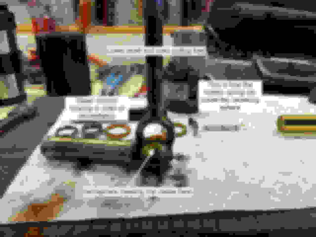
Whew. When you're slipping the shift tube up into the locking plate, notice that it has a flat spot to align the shift lever with the lower column shift ear. Clock the tube into the locking plate so they line up flat and you're golden. Here's what that looks like looking down the shift bowl: Move the shift tube back & forth in the shift lever bowl until you get the 4 parts of the lock plate in place correctly.
I had a little trouble with one of my columns and decided gravity would help. Here a different way to get the shift tube and shift lever bowl to align and install the lock plate: When aligning shift tube and shift lever bowl, gravity can be your friend.
Here's one more view of the lock plate in place correctly as seen from the top: On the right is where the lever goes. It's released with a simple drift and hammer from underneath.
Shift Lever
We use this lever every time we drive. Shouldn't it be smooth and right? It's spring-loaded inside the lever bowl, but you can knock its retention pin on the outside of the bowl with a drift from underneath.
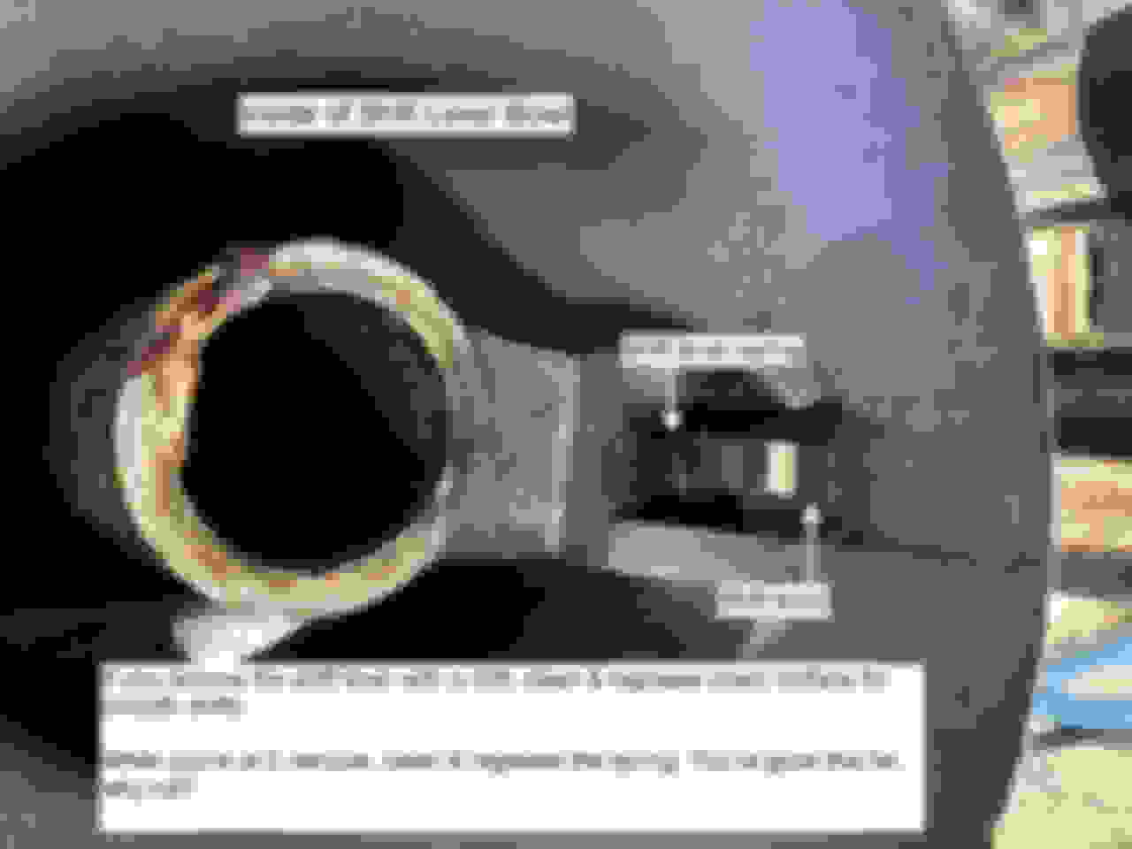
A naked shift lever bowl. Remove, clean & regrease the lever return spring and all sides of the bottom of the lever itself. You want it to move back & forth smoothly as you shift. Grease helps.
Let's stop there before we move on to the complex upper column parts. Hope you're learning like I did.
So the rubber is on the outside, the shift tube is back on, the lock plate is in. We're well on our way. But now we have to get the more complex upper column pieces back together.
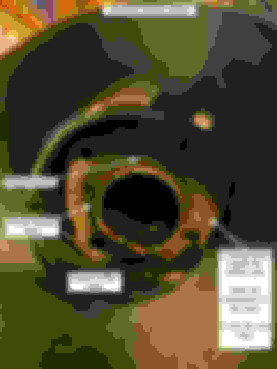
Looking down into the shift lever bowl, you should see this inside the column: A lock plate just waiting for a reinstalled Support or Stop Plate. I don't know what the 4-bolt part is called.
I guess this is the Support
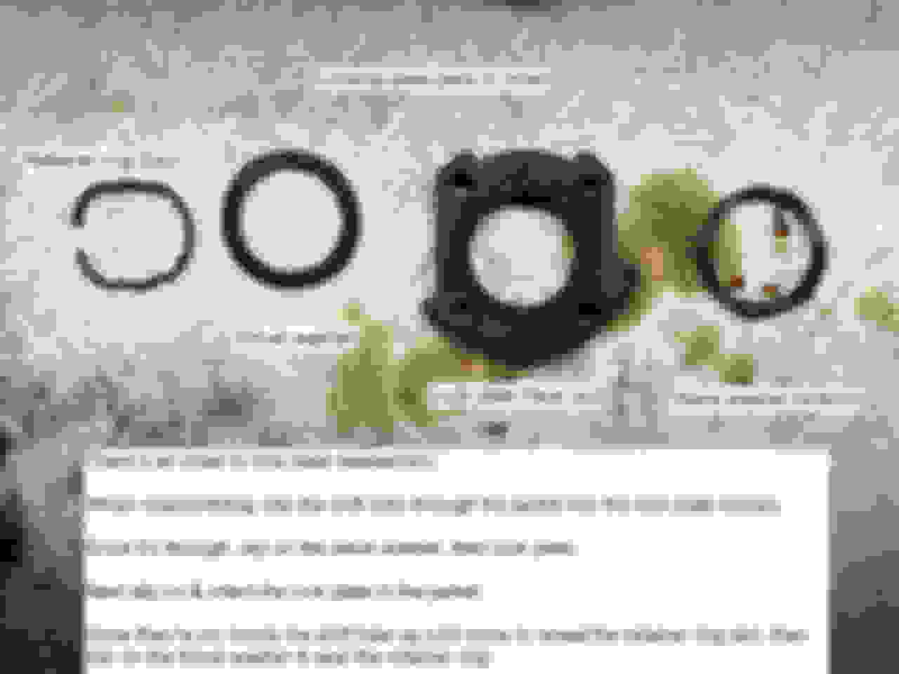
Here's what goes in. It's simple to install - just 4 bolts that need a 3/8's socket on an extension. Just be sure that the shifter plate is greased on on the right of the column so your shift lever will index to it and shift the gears. Here how it should look going in: I wish the CSM was more clear about the name of this part. At least it's easy fo install.
Here's what it should look like after installation: Grease up the insider where the lock shoes grab and be very sure to grease the walls and outside edges of the pivot pin holes to make reinstallation of the actuator housing easy.
Steering Shaft
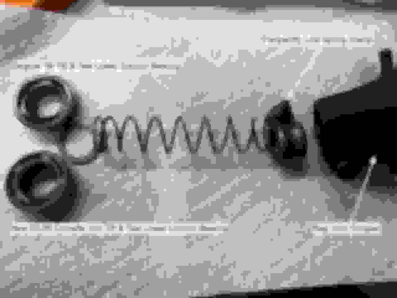
Not to make light of this but reassemble the steering shaft onto the centering sphere with lots of grease. Fit the 2 well greased hemispheres into the upper yoke being sure that the spring slot is aiming straight down column to allow installation of the hidden spring. You'll probably have to fiddle getting the sphere into the upper yoke, but eventually you'll find the right orientation to get it back it. Do this with gloves. It's a greasy affair. Here's a shot that may help: Slip the centering sphere back into the upper yoke, position it so that the spring void points straight down-column.
Once the sphere is in, reverse the 90� trick to reinstall the lower shaft: Connect the two shafts. We'll get to the hidden spring in a moment.
To get the hidden spring and stop back in, remove the upper shaft from the upper yoke and nudge the spring back into the sphere using the upper shaft. Then compress the spring with a screwdriver to install the spring stop. This exploded shot may help: Nudge the sphere spring back into place by slipping it down the upper yoke with the upper shaft as a drift to shove it in place. Then slip the stop into place.
Once you have the steering shaft reassembled, slip it into the column from column-top: Slip the steering shaft back into the column.
Good stopping point. Next up is yet more on the actuator housing. It's complex and deserves its own post.
Reassembly 3: The Actuator Housing Dilemma
The only real dilemma here is whether or not to remove the locking shoes. If you do it, you commit to painstakingly reinstalling very strong, easily bent springs as you shove and align mounting pins just so. If you leave them in place, you commit to pulling back & holding the tilt lever when reinstalling the actuator housing. The latter is the less of 2 evils. Grease the housing to ease reinstallation
Preparing the Housing:
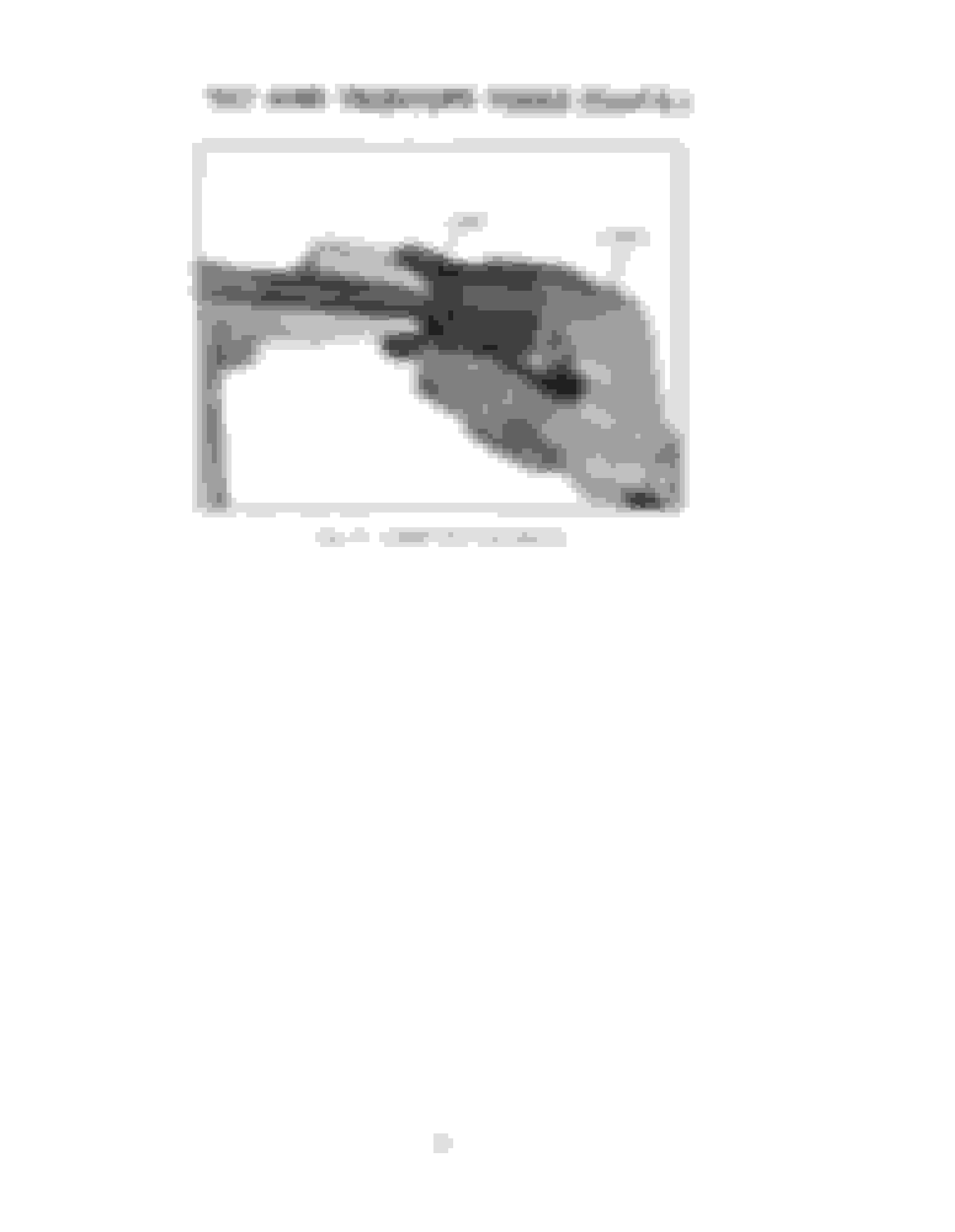
The rotational-critical upper and middle bearings live inside the the actuator housing. See my post above about reinstalling with the ball bearing facing the correct direction. This shot shows how to put the bearings back in. The short version is upper ball bearings face column-up, lower ball bearings face column down to sit correctly in the respective bearing races. Have a look: The upper bearing is on the left, the middle bearing is on the right. The upper bearing has a "race seat" which holds it in position to create spring pressure and suspend the steering shaft inside the column. This creates good rotational movement.
Once the housing is greased and the bearings are in, you're ready to reinstall it. Put the tilt lever back on the housing and screw it _all_ the_way_in. These tiny stalk threads love to strip if you give 'em the chance. First slip the housing over the upper yoke. As it gets close to part below it, pull back on the tilt lever to open the locking shoes. You'll probably need a few tries. Try a few different tilt positions to see what works.
You're done when the housing is back on and the shoes feel right and the pivot pin holes look like this: This needs a little playing around. The key is to hold back the tilt lever while sliding the actuator housing on to the support below.
Now just tap the pivot pins back in. Be sure they're really flush so that the trim cover will slip on easily: Tap, tap with a rubber hammer to put pivot pins back in. They're shaped to self center within reason, but if you're way off start again.
So now you have a pivoting housing, but you need to lift and lower it manually. Wouldn't it be easier if it would spring up and you could just pull it down? That's what the tilt return springs do.
Pull the tilt lever back and put the housing in its upmost position. This is the "spring relaxed position" which make it as easy as possible to reinstall the tilt return springs. Hook the hidden ends into the lower part. They're easy to find it you orient the visible spring ends pointing down. Then use pliers or a screwdriver to pull forward on each one in turn to snap the top of the springs back on their perches. This may help: Pivot return springs pull up on the upper column to make it easy to tilt.
Once those springs are on, we can look at the telescoping upper shaft
Telescoping Upper Shaft
This is a pretty simple part, but it can go wrong. It took me 30 minutes or more to figure out I'd installed the Upper Bumper wrong, but I knew it was wrong since I couldn't lock the column. Let's have a look: Grease the outside of this shaft to let it slide easily. Also grease the locking wedge and upper bumper so they slip easily into the groove in the upper yoke to lock.
Here's the upper bumper orientation that worked for me on this column - groove/slot toward column bottom. I've seen them work with that bumper reversed groove/slot oriented toward column top. To slip this back into the upper yoke be sure the wedge and bumper are flat, not cocked or the upper shaft won't go back in.
Well that's about it except for reinstalling the turn signal upper switch and horn ring with my goofy home-brew tool.
Oh, how did that crusty rusty shift lever come out? Have a look: Evaporust and a little polishing with #0000 steel wool. Boom perfectly nice shift lever!
Thanks for that. So the pins must be able to slip past those rings on the springs when you turn the wheel yet hook them on the way back to cancel (I guess?). Mine do not always cancel consistently. I'd say that 50% of the time, they cancel properly. This thread has definitely got me thinking that it might just be an adjustment. Will be interesting to look at it when I get some time, armed with all this knowledge you have most graciously given us.
If it�s inconsistent, I�d look for a cracked or worn down pin which isn�t contacting the cancellation spring consistently on the back side of the horn ring. Or I�d look to see if the cancellation spring is worn or stuck in some dried grease/dirt combination. Sorry I don�t have a picture ready to go for you.
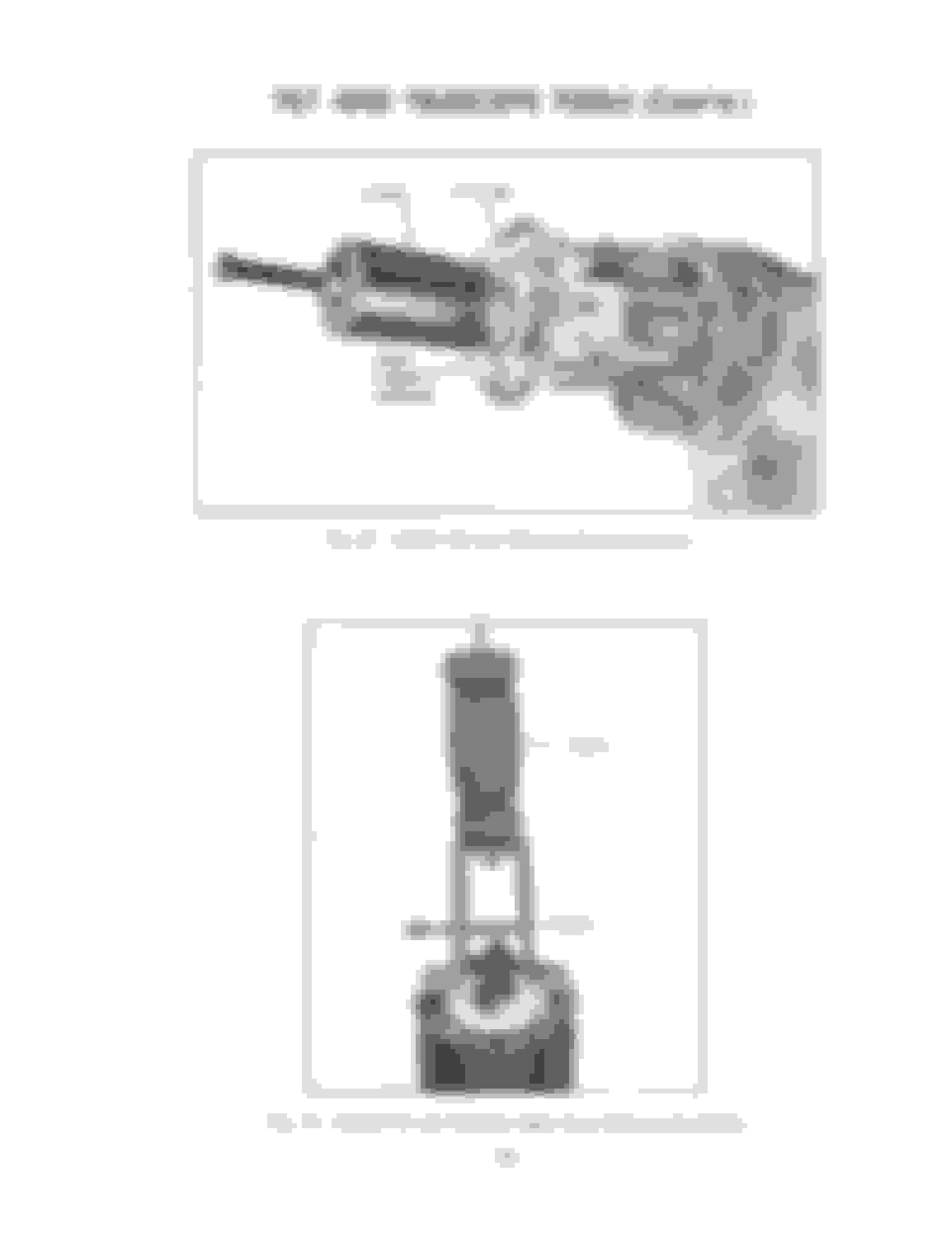
Have a look at my post on The 1966 Preliminary Product Information PDF. I found the tool photos in there.
My hunch is that to the degree that they diverge from the later tool data, Olds was still figuring out what to do so allow their dealers to work on then-new Tilt & Tele columns.
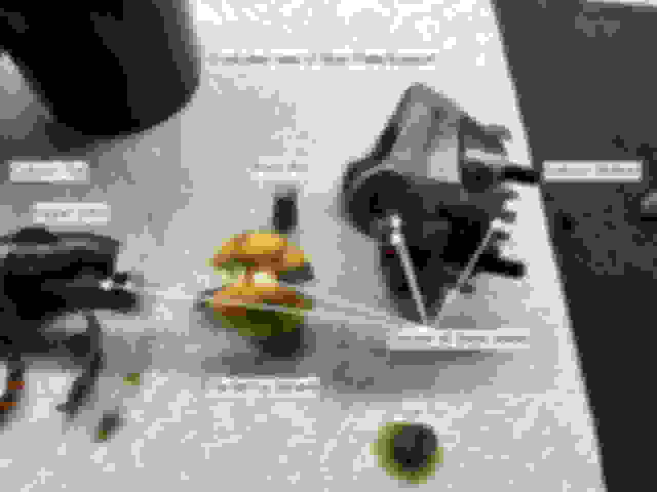
For anyone following along, I was curious whether a new 63-66 Corvette lower column bearing would fit a '66 Olds Tilt & Tele column
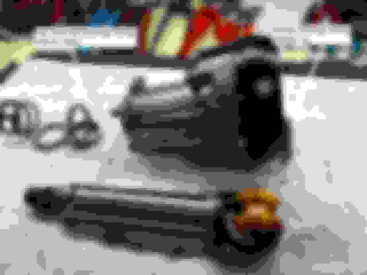
It turns out they do fit exactly right. And they may even be better built. On the left are the 2 bearings side by side. The only difference is new vs. old & the vette bearing has 4 retention ears to the Olds 3 Yes a 63-66 Corvette Non-tilt lower column bearing is the same as the 66 Olds Tilt & Tele lower column bearing.
Several of my columns are missing the lower clamp which holds the lower column spring in place. I've ordered some Corvette clamps guessing that they'll fit too. The clamp is there to suspend the steering shaft in the lower, middle and upper bearings. Over the years, it gets lost and the rag joint coupler does just about the same spring retention job, but with less spring force than Saginaw designed. At this point, why not just put it right?
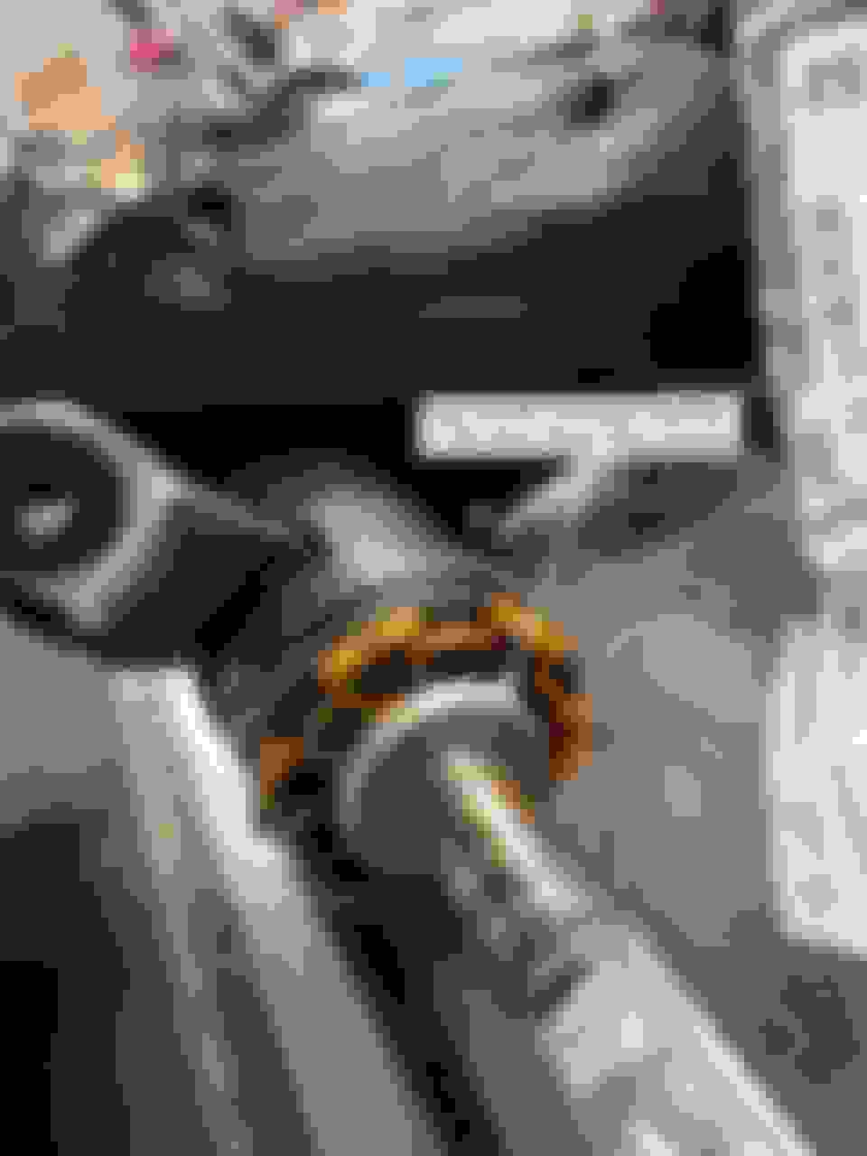
If I read that I'd be skeptical too. Here's the bearing in place on the Olds Tilt & Tele column lower adaptor: Vette bearing in an '66 Olds Tilt & Tele column
Here's the lower column fully assembled with the new bearing and correct clamp in place. See the part number and description if you'd like a new lower column bearing too.
I'll let you all know if the clamp works too. Guessing it will.
I got the early 60's Corvette lower column spring clamps in today. They are an exact fit to the Olds column.
For reference I'm talking about the clamp 2 posts up which sits between the lower column bearing on the left & the rag joint coupler on the left.
The Corvette part that fits is the middle clamp in the picture 2 posts up holding a spring tight to the left.
2 or more of my Olds columns are missing this clamp. I'm sure they were lost along the way in some removal or other operation over the past 55 years...
You can definitely do without it. The rag joint coupler will retain the lower column bearing spring just fine.
But I thought since I'd gone this far, why not have the spring compressed in the way & at the rate that Saginaw designed it to have? In for a penny, in for a pound as the Brits say.
Anyway, nice to see GM parts work across brands, models and years every once in a while. We big car guys lose on this so often, it's fun to report a win!
I'll let you guys know here when I start using these restored columns. At the moment I'm waiting for the body shop to finish painting the trim pieces of my best one. I wouldn't hold my breath, but I'll get there in the next few weeks or months.
I disassembled my ‘66 Starfire column last week and found the upper column bearings facing a different way than the other 2 columns I’ve done.
There are 2 bearing assemblies in the upper column, let’s call them top-most and middle for reference.
In the 2 previous columns I’d opened, I found the top-most ball bearings facing up and the middle bearings facing down.
In my ‘66 Starfire I found the top-most ball bearings facing column-down - with the nylon race facing column-up. I found the middle ball bearings facing up and the nylon race facing column-down.
The action on the Starfire column was very smooth, so I didn’t “correct it” per my experience with the previous columns. My next step is to reverse the bearings in my worst column and see if that improves the rotating action. There’s a noticeable drag on what I think is my highest mileage one, but it may just be that I have the bearing orientation wrong in the posts above.
I’ll note the experiment results here when I have them. Orientation might matter, or it might not matter, or the driving factor may be how well balanced the upper and lower column springs are suspending the steering column shaft in the column tubes/bearings.
More to follow. Just wanted to report the variance which leads me to question my logic above.
Y'know how sometimes you put a lot of effort into something and get it working, but later discover you were wrong? That happened to me here.
I just reviewed all of my literature. Neither the Chassis Service Manual nor my Assembly manual have any detail on what way the upper column bearings should be installed. They fit with either the ball bearings facing up or down, so it's not really clear unless you test. Which I did this afternoon. On 3 upper columns. Just to be sure.
After my Starfire column last week had the upper column bearings reversed from what I'd been doing, I questioned whether I had it wrong. I was wrong. At least if smooth rotational action is the goal for steering column bearings.
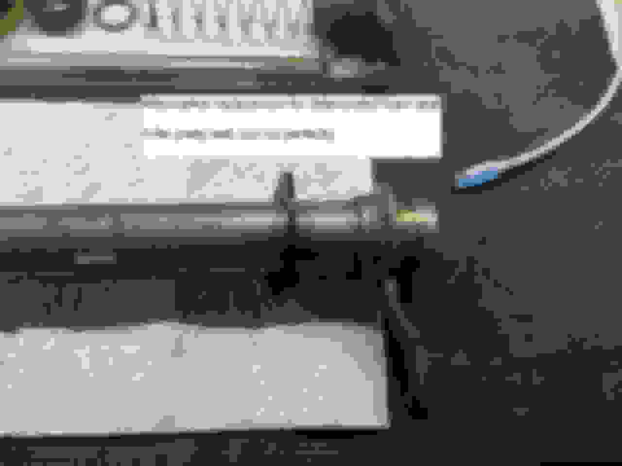
This afternoon I disassembled both of my spare columns & reoriented the bearings to the way I found the Starfire column. Then I spun 'em on the bench like a child's toy. Both wound up substantially smoother. Then I tested the reorientation on a spare upper column housing I had. It spun like a mad dreidel. I.e. - perfectly.
Accordingly, I'd like to share what I consider best practice or correct practice with the following photos to be sure the point is clear.
Here's how I have the upper column bearings in my 1966 Tilt & Tele columns now: What I believe to be the best upper column bearing orientation. Call it "nylon facing out" if you like. Top most ball bearings facing column down, middle ball bearings facing column up.
Here's a view as the bearings sitting on the upper column shaft just to show what would be ordinarily hidden inside the upper column housing: Another way to put it is the ball bearings should face each other with the nylon retainers facing out. This orientation got me the smoothest rotational action across 3 different '66 Tilt & Tele columns.
MODS -- if you'd like I'd be happy to correct the errors in the posts above, but I'd like to coordinate with you such that they don't disappear, but are merely made right as necessary. Hit me up privately if you'd like me to correct the posts above. I'd like to avoid pointing anyone the wrong way in case they don't read this far.
Sorry to all for the error. The bearings will work either way. They just work better (smoother) when oriented this way.
Chris
Gang,
I've been working on 66 big car tilt & tele columns since the 80's and thought it was time to write down the common problems, solutions, and how to get it apart. I always thought this was a fun feature and especially like the aircraft yoke looking steering wheel.
I'm an amateur, so read if you're interested, but please take your car to a professional for anything that might threaten your or your passenger's safety.
Fair warning that this might get long, so I hope I don't bore you too much.
Background
'66 was the first year for the B (88's) &C (98's) &E (Toronado) cars to get a column that tilted & telescoped. In 65, Olds offered tilt only, no telescoping, so that's one way to see what year column you might have. I'm told that our Olds columns share 90% of their internal parts with Cadillacs of the same year, so if you're hunting for rare parts, that's another avenue to run down. Unless I miss my guess the last 10% of the differences would be the trim parts which differentiated Caddy from Olds. The lower shaft may be different length for Caddy's vs Olds, so don't expect to just drop in a Caddy column in your Olds.
Also you cannot swap a Toronado column into an 88/98. The Toros had a longer lower shaft, but the upper shaft & trim pieces can swap into an 88/98. In the Toros, the tilt & turn signal stalks were black metal, not chrome like the 88's and 98's, but the parts can physically swap with no problem. The turn signal bowden cable for the Toro's is also longer that the 88/98 cables, so they don't swap either. While the Toro and 88/98 steering wheels had a similar design, the Toro wheel is deeper than the 88's/98's
I learned yesterday that these columns were manufactured by Saginaw and that a guy called Eldorado George in Florida bought the tooling when Saginaw shut down and now has a business repairing them. He specifically declines columns owners have messed since it costs him too much in time & parts to fix other's mistakes. See his videos on Youtube for more. A careful thoughtful engineer was my conclusion.
Common Problems
Generally these columns are very robust. When you could find them in the junkyards in the 80's, you could swap 'em right in they'd usually work. The design is fundamentally sound & reliable in the best GM tradition. These columns were also designed to be serviced, not replaced and frankly they don't need much service owing to well machined parts. The only exception I'd call out are the plastic/nylon parts which are now well into their 5th decade. No one expected anyone to keep these cars that long. Just be aware that the plastics can be brittle and are just not available.
Turn Signals
The first problem I encountered in the 1980's was that the right turn signal was getting harder & harder to activate. The turn signal switch is a 2 part system with an upper stalk switch which physically moves a bowden (spiral encased steel) cable to activate the lower electrical switch found on the lower left of the column. A left turn action pulls the cable rearward, and switches on the left turn signals. A right turn pushes the cable forward to activate the right side lights. My cable had either become bound up, or otherwise out of alignment beyond the movement of the adjustable (slotted) lower switch. It wouldn't push the cable quite forward enough to activate the electrical switch. The fix at the time for me was a new boneyard column, which worked great for decades. Yesterday I carefully unbent the upper bowden cable crimps at the upper switch and slipped the cable forward about 1/16" to make a more positive connection with less effort when turning right. I recrimped it and it works as well as I've ever seen.
Horn
What got me into a long thrash over the past few days was chasing down an intermittent horn problem. My horn worked when turning, but not when going straight. I figured it was the upper column horn ring not contacting the horn pin consistently. I was wrong, wrong, wrong. It turned out the column was 100% fine. The problem was a latter day rag joint whose internal metal strands had broken and were not providing a consistent ground to the column. I fixed that with a simple ground strap and all is right with the world.
But along the way I learned how these horns work:
A power wire runs up from the harness into the column and terminates in a small brass connector which is like a reverse "L" shape. That "L" shape holds a spring loaded pin against the bottom of the plastic/brass horn ring. The ring rides against the pin for 360� of travel. The top of the plastic horn ring has 3 brass tabs which run through the plastic to the underside ring. Those 3 tabs provide power through a steel spring which expands when telescoping to provide power through one more brass ring to the steering wheel buttons.
While I was digging around wrongly convicting the horn ring connection, I learned that the underside of the brass ring eventually gets a groove from riding on the horn pin. The 18" diameter horn pin also wears down a tiny bit. If you've lost connectivity and your column ground is good, you can remove the brass part of the horn ring by bending the 3 upper tabs. If you do, clean it, flatten it'll and sand out the groove if you like. Just for good measure I shimmed mine with a very thin piece of mountain bike inner tube rubber between the brass and plastic on the underside. The reason I shimmed it is that I found that the plastic part of the horn ring had warped over the decades from flat to a little wavy. Unless you have a problem, there's no need to shim.
So that's the introduction.
Chris
Thank you for quite the information on this type of column. I have had this particular column in my 65 olds dynamic 88 for years and worked just fine until recently when the cable that attaches inside to the plastics inside the column broke (became brittle(. I had to manually operate the cable by hand as this particular car has Corning lights. This particular turn signal switch is very hard to locate. Had to cruise quite a few junkyards , also was lucky in dissemble the switch to repair.would you happen to have the address of this person that can repair my column here in florida? If so my email address is hermandolison@yahoo.com I don�t have the experience to tear it apart and would rather pay someone to do it.
Have a look at my post on The 1966 Preliminary Product Information PDF. I found the tool photos in there.
My hunch is that to the degree that they diverge from the later tool data, Olds was still figuring out what to do so allow their dealers to work on then-new Tilt & Tele columns.
Chris
As you can tell from my user name, I'm an outsider who decided to search for the turn signal actuator assembly for the tile / tele column...and came across your thread. Many thanks for the pictures you provided, when mine was assembled (back in 2010), there wasn't much info. I had a '66 Chevrolet shop manual which detailed the disassembly / assembly of the column. This was our reference, but my trouble was the bowden cable actuator (the small bell crank) had the cable arm broken...your picture gives me what I needed to understand what I needed to have the part 3D printed (on my column, the cable had frozen in the casing, snapping the bell crank)...currently the turn signal switch is hanging on my tilt lever (using a cable extension), and using my finger to move the switch (hey, it works). I just need to get my part back from someone who was supposed to know someone...nothing yet.
Brian
3D printing the broken part is a great way to go. I don’t have a 3D printer or frankly the skills to drive one, but if you’re successful please let us know here. There are likely quite a few columns out there on the shelves of enthusiasts who are lacking one or more of the rare and brittle plastic parts in the upper column.
Another fix would be to hunt down a replacement turn signal from another GM from your year and swap your Bowden cable in. I believe these columns were most common in Cadillacs so that’s a good place to start a hunt. There’s also a gentleman in FLA who rebuilds these as a retirement hobby business, but it’s over $1000 as I recall. His work looks just great though, see YouTube for his process. Very thorough.
If you go the replace it route, don’t be surprised if you have to buy a whole column just to get the upper turn signal switch.
I don't have the knowledge to operate a 3D printer either, will have to outsource to have it done.
Keep hoping to come across a Caddy or Olds in a pull a part yard before it has been stripped, as the price of columns are close to $1,000...a few bucks over my budget.
Now I was told by a friend who was a 40 year GM mechanic, that Mopar used the same setup on their tilt & tele columns for '66...should I be lucky enough to find one of those (have not been able to verify this)
Anyone know of anyone that has started to make a new bell crank that goes in the upper turn signal switch and operates the Bowden cable?
Took out the piece from the turn signal switch and scrounged around on the floor and got lucky, found the broken piece and glued it together for now, so I can have someone copy them if I can�t find anyone that makes them already. I�ll have extras!
Took out the piece from the turn signal switch and scrounged around on the floor and got lucky, found the broken piece and glued it together for now, so I can have someone copy them if I can�t find anyone that makes them already. I�ll have extras!
I could swear I saw someone on here started making these out of metal and selling them on Ebay. It was a post on here not long ago, maybe a year tops. I will search around.
Eldorado George on Youtube just put out a series of videos on the til & tele steering column. This is excellent work and combined with the info contained here in this thread you can really understand how these things work. The videos certainly filled in some gaps for me and answered several questions I still had even after studying CFair's excellent posts. Info like this is truly what makes the internet such an incredible resource.
That is a superb video. I'll have to catch the rest of his series. He is _the_ authority on these columns. If I had not redone my own personally, I'd send mine to him in an instant.
That is a superb video. I'll have to catch the rest of his series. He is _the_ authority on these columns. If I had not redone my own personally, I'd send mine to him in an instant.
Cheers
Chris
Looks like he made these particular videos "Members Only" recently. He's got his membership fee set at 250 bucks a month. That's quite an arsehole move to be honest.
I had a brief conversation with him about restoring the columns. He seemed a little annoyed with me asking questions.
The nicest way I can put it is he’s running a niche mechanical / intellectual property (knowledge) business. I’m not. He confirmed that he bought the tooling from Saginaw to restore these columns and it’s a business he hopefully enjoys. I can confirm that specialty tools would make restoring a lot easier.
Ergo, I’m volunteering my less than professional level advice & photos.
And he’s protecting his business. I have no problem with that but choose my way for my reasons.
He’s still the authority on these columns, but I’m happy with how my hobbyist level restorations came out.
Chris
I agree. I'm not so sure behaving like that is good for business though. His attitude has certainly driven me away. His target market is probably what, 1000 people? Why **** them off by being so possessive and defensive? Of course, it's his thing and he can do it his way but, personally from what I've seen, I won't do business with someone who acts like that because it's just not worth it to me. I think I've seen enough and I've been around the block enough to recognize trouble when I see it and that right there isn't worth the hassle. I'll take the Cfair method myself.
That video he posted of him berating the Amazon driver for pulling into his driveway when the guy delivered a parcel to him told me everything I need to know about the guy.
Last edited by ourkid2000; May 5, 2025 at 09:36 AM.