When you click on links to various merchants on this site and make a purchase, this can result in this site earning a commission. Affiliate programs and affiliations include, but are not limited to, the eBay Partner Network.
Gang,
I've been working on 66 big car tilt & tele columns since the 80's and thought it was time to write down the common problems, solutions, and how to get it apart. I always thought this was a fun feature and especially like the aircraft yoke looking steering wheel.
I'm an amateur, so read if you're interested, but please take your car to a professional for anything that might threaten your or your passenger's safety.
Fair warning that this might get long, so I hope I don't bore you too much.
Background
'66 was the first year for the B (88's) &C (98's) &E (Toronado) cars to get a column that tilted & telescoped. In 65, Olds offered tilt only, no telescoping, so that's one way to see what year column you might have. I'm told that our Olds columns share 90% of their internal parts with Cadillacs of the same year, so if you're hunting for rare parts, that's another avenue to run down. Unless I miss my guess the last 10% of the differences would be the trim parts which differentiated Caddy from Olds. The lower shaft may be different length for Caddy's vs Olds, so don't expect to just drop in a Caddy column in your Olds.
Also you cannot swap a Toronado column into an 88/98. The Toros had a longer lower shaft, but the upper shaft & trim pieces can swap into an 88/98. In the Toros, the tilt & turn signal stalks were black metal, not chrome like the 88's and 98's, but the parts can physically swap with no problem. The turn signal bowden cable for the Toro's is also longer that the 88/98 cables, so they don't swap either. While the Toro and 88/98 steering wheels had a similar design, the Toro wheel is deeper than the 88's/98's
I learned yesterday that these columns were manufactured by Saginaw and that a guy called Eldorado George in Florida bought the tooling when Saginaw shut down and now has a business repairing them. He specifically declines columns owners have messed since it costs him too much in time & parts to fix other's mistakes. See his videos on Youtube for more. A careful thoughtful engineer was my conclusion.
Common Problems
Generally these columns are very robust. When you could find them in the junkyards in the 80's, you could swap 'em right in they'd usually work. The design is fundamentally sound & reliable in the best GM tradition. These columns were also designed to be serviced, not replaced and frankly they don't need much service owing to well machined parts. The only exception I'd call out are the plastic/nylon parts which are now well into their 5th decade. No one expected anyone to keep these cars that long. Just be aware that the plastics can be brittle and are just not available.
Turn Signals
The first problem I encountered in the 1980's was that the right turn signal was getting harder & harder to activate. The turn signal switch is a 2 part system with an upper stalk switch which physically moves a bowden (spiral encased steel) cable to activate the lower electrical switch found on the lower left of the column. A left turn action pulls the cable rearward, and switches on the left turn signals. A right turn pushes the cable forward to activate the right side lights. My cable had either become bound up, or otherwise out of alignment beyond the movement of the adjustable (slotted) lower switch. It wouldn't push the cable quite forward enough to activate the electrical switch. The fix at the time for me was a new boneyard column, which worked great for decades. Yesterday I carefully unbent the upper bowden cable crimps at the upper switch and slipped the cable forward about 1/16" to make a more positive connection with less effort when turning right. I recrimped it and it works as well as I've ever seen.
Horn
What got me into a long thrash over the past few days was chasing down an intermittent horn problem. My horn worked when turning, but not when going straight. I figured it was the upper column horn ring not contacting the horn pin consistently. I was wrong, wrong, wrong. It turned out the column was 100% fine. The problem was a latter day rag joint whose internal metal strands had broken and were not providing a consistent ground to the column. I fixed that with a simple ground strap and all is right with the world.
But along the way I learned how these horns work:
A power wire runs up from the harness into the column and terminates in a small brass connector which is like a reverse "L" shape. That "L" shape holds a spring loaded pin against the bottom of the plastic/brass horn ring. The ring rides against the pin for 360� of travel. The top of the plastic horn ring has 3 brass tabs which run through the plastic to the underside ring. Those 3 tabs provide power through a steel spring which expands when telescoping to provide power through one more brass ring to the steering wheel buttons.
While I was digging around wrongly convicting the horn ring connection, I learned that the underside of the brass ring eventually gets a groove from riding on the horn pin. The 18" diameter horn pin also wears down a tiny bit. If you've lost connectivity and your column ground is good, you can remove the brass part of the horn ring by bending the 3 upper tabs. If you do, clean it, flatten it'll and sand out the groove if you like. Just for good measure I shimmed mine with a very thin piece of mountain bike inner tube rubber between the brass and plastic on the underside. The reason I shimmed it is that I found that the plastic part of the horn ring had warped over the decades from flat to a little wavy. Unless you have a problem, there's no need to shim.
O.k., so you want to dig into you '66 big car or Toro tilt and tele column because it's not working quite right.
Here's what to do... Use a tiny screwdriver or better yet soft teflon pry tool to pop out the center cap.
Removing the telescoping lock ring Remove the two outer screws, then unscrew the black center piece.
Next you'll be greeted by a tightly torqued 7/8" nut which holds the steering wheel onto the column. Remove it store it somewhere easy to find. Before you pull the wheel off, use a Sharpie to mark a clocking line between the shaft and the wheel. Otherwise you'll burn a lot of time trying to reclock the wheel after your work.
Next use a steering wheel puller to remove the wheel. The one I've got uses bolts that have a 1/2" head...
Make a clocking position mark on the wheel and center shaft to know where to put the wheel back on... Don't just yank the wheel off, you're likely to bend or break it all these years later, just use a puller to remove the wheel from its splines.
Once the wheel is off, you'll see the horn ring and turn signal sitting inside the upper column cover.
Once the wheel is off, here's the horn ring. It can get wavy which may create a horn connection problem, but has not in my case.
As you can see everything mechanical is buried inside the upper cover. I pry mine from the back & low (to not show tool marks) and gently knock it by turns at 12:00, 6:00, 3:00 and 9:00 to nudge it off. Be gentle here. This is a highly visible trim piece. All the guts of the upper column switches live inside.
Once the trim is off, you can see the combination turn signal (ts) and horn ring. The C clip which holds the horn ring to the column is backed by a very strong spring. You can gently use a screwdriver to get it off, but you will need a tool to get it back on. More on that later. Here are some parts descriptions & things I've found: Removing this piece involves popping the C clip, disconnecting from the wiring harness, disconnecting from the lower turn signal switch (the bowden cable & 3 upper screws.
Here's a look from the right side. This is where the column power comes in and where the steel cable connects to the lower switch. If you're going to remove the upper switch both connections to the lower parts need to be disconnected. I disconnect the power connection at the upper switch and leave it hanging. I disconnect the lower turn signal switch at the bottom since it's an integral part of the upper TS/horn ring switch. When you're removing the upper switch, rotate it to allow the lower TS connector to come freely up through lower column. To get it apart, 1st pop the c-clip, then remove 2 connections to the lower TS switch and the wiring harness.
You can remove the horn ring using just a screwdriver like so, but it may be safer to use the tool as I show below for reassembly Quicker with screwdriver. Safer with tool.
Lower turn signal electrical switch. It's adjustable and spring loaded. They can still be bought new if you need one.
Using the homemade tilt & tele PVC tool.
This is a replacement for a long gone Kent Moore tool which allows you to lock the telescoping feature of the column and recompress the very strong spring which holds the horn ring against the C clip. I've documented its construction before. Dig around under my user name to find out how to make one. You may be strong enough to force the horn ring back down without it, but you'll need to have the horn ring clocked to receive the C-clip and press down and slip the clip in. I count three hands. Or a helper. Neither one of which I have...
First up screw the threaded rod into the telescoping shaft. Then lock out the telescoping feature of the column: If you don't lock the tele feature, it's even harder to compress the horn ring spring.
Once the tele feature is locked out, you align the notch of the PVC with the radius of the c-clip and tighten the coupler nut to force the PVC down and, in turn, force the horn ring down so the c-clip can release. A little notched PVC tool to allow installation and removal of the spring backed horn ring.
Whether removing or installing the c-clip, the goal is to push the horn ring down far enough to make it easy to slip the clip on & off. Before trying, clock the position of the horn ring with the spring off the column so you know the best position to slip the c-clip into.
Once the horn ring is off, you'll see the turn signal switch and on the lower right the horn pin with a wire running out the back. Up top, just 3 screws hold it in, but do those last. Before removing them, make sure you've disconnected the power and bowden cables. Here's how.
Here's a look at the lower turn signal switch. You'll have to remove the bowden cable from it to remove or replace the upper switch. Then you'll need to fish the cable up through the column
Removing the electrical connection from the harness. I've disconnected this wire both at the column and just yanked it out of the harness. The best way is to pop the brass clip in the column so you don't destroy the harness along the way.
I use this tiny screwdriver to pop GM electrical terminal tangs all the time. In GM's long-used Packard 56 system terminals are held in place by bent tangs which can be unbent to allow them to be removed. A great clip release screwdriver. Get one if you work in wiring harnesses
In the case of the horn pin, the brass terminal holds a small spring (that loves to get lost!) which forces the horn pin forward. On the underside of this terminal is a tang which holds the whole thing in place. Release the power to the column using a small screwdriver to bend the retention tang upward.
O.k. Good stopping point. Just in case there's a crash I'd rather not lose all those photos and typing. Hope you guys are enjoying this.
O.k. So you've disconnected the lower turn signal switch cable, and you've popped the electrical connector behind the horn pin. The last task before heading to the workbench is remove the 3 screws you see on the front of the turn signal switch. Then rotate the switch as you slip it out of the column to fish the bowden cable through the inside of the column. It's a weird shape, so rotating it helps it clear mechanical parts in the lower column.
Here's the turn signal switch from the front. I look for any broken parts, particularly plastic ones and generally clean and grease it if it looks o.k. 1966 big car tilt & tele turn signal switch from the front. After removing the lower turn signal cable and the power cable from the harness, unscrew the 3 screws you see holes for here.
Back view. This shows how the bowden cable (left) translates up/down movement of the turn signal stalk to forward/backward movement of the lower electrical switch. In the middle see the arch-shaped connector? Its shape & position behind the horn pin is _very_ important. If this arch is not leaning forward (toward the horn pin) at an angle, it can ground the entire column. You'll know if it's not bent forward because the horn will sound _immediately. One trick is to pre-bend it to about 70� forward at the top, then when you push the terminal back it hits the plastic and clears the column metal. 1966 tilt & tele turn signal switch from the rear. The shape of that metal connector is critical. Or, at least, I've gotten it wrong for years...
If you're worried about the arch shaped connector clearing the column, or can't get the shape quite right enough, slip a small slice of bike inner tube behind the brass tang. It will be held in place by the screws that hold the turn signal switch to the column. Best move is don't use extra parts, but here's an idea if you goof like I did for years... Get the brass terminal back leaning forward or insulate with a slice of inner tube. Otherwise the brass tang can contact the column and you'll have a new feature: constant horn...
I don't recommend any servicing here other than cleaning & greasing what you can get at without taking the switch further apart. The risk of plastic breakage is just too great. If your plastic is not yellowed, then it may be in good enough shape to really clean & degrease. If it's yellowed, leave it together and use a light oil on moving parts. Here's how to fix the right turn signal too:
Slip the bowden cable 1/16" forward to fix a bad right turn signal. Or slip it back if your left turn signal isn't working easily.
Once your bench operations are done, it's time to put the cleaned, greased switch back in the car. That sounds like a good stopping point. Up next - reinstallation.
Just curious. Often times the turn signal cancelling isn't working on these things. Just wondering what part of this switch assembly is responsible for that? Do you know what usually breaks that ultimately causes this?
O.k., onto reinstallation of your cleaned, greased turn signal switch, with it's arched brass terminal leaning toward the horn pin so it doesn't ground on the column...
The first job is to fish the turn signal switch bowden cable through the lower column rotating it as you go and generally nudging it from right to left since it has to connect to the lower turn signal switch on the left of the column. Once that's fished through the column, and through the foam insulation ring, you'll be able to hang the upper turn signal switch on the column. You hang it there while you get ready to reconnect the electrical connection - either using a bent tang or the rubber insulator to keep it from grounding on the column.
Setting up the tight tolerance electrical connection
The tricky part of reconnecting the electrical is you have to set it all up before popping it back in.
1) The horn pin must be in its hole aiming forward.
2) The spring must be behind the pin in its column.
3) The lower brass connecter tang must be back in a downward pointing position to stop against the plastic.
4) And above all the rear upper arch-shaped tang must be bent forward toward the horn pin to avoid grounding the column. Or use an insulator.
Next, hold the spring against the pin and slip the connector back in. If you did right, the lower tooth engaged and the arch shaped tang should be sitting very tight to the rear of the switch plastic.
Sorry I don't have a picture of this operation. Not enough hands. Have a look at the post above just after the screwdriver pictures and imagine that in reverse...
Reattach the upper plastic turn signal switch to the column
Next screw in the 3 screws to reattach the turn signal switch to the column. If the horn sounds when it gets tight, your arch brass tang is grounding the column.
Reattach the upper TS switch bowden cable to the lower TS electrical switch
Slip the cable coils onto the lower switch pin. You'll find the switch pin on the inboard side of the switch about in the middle. Sometimes these break off. If so, get a new one. If I recall Charlie Jones actually knows the part number! Secure the cable to the switch pin using the spring steel clip. If I breaks, I have no idea where to get another. Once the cable is on, then use the 5/16's hex head to secure the clip to the lower switch.
Once the cable is back on the lower switch, remount the lower switch on the column. This is a slight pain since the upper 5/16's screw hole is a little hard to get at. I usually start with the visible lower one just to locate the and get it on, but loose, then hand tighten the upper one. I usually have the switch about 1/3 of the way back from the front of its mounting slot, but your column may be different. Remount your turn signal stalk and test it as if you're driving it to get to the correct forward/aft position. Expect a little trial & error.
Whether your upper cover is on or off, your column should now look about like this: Test fit the C-clip before trying to fit it with the spring in. Mark a position on the front of the horn ring to align it with the clip slots correctly.
Horn ring clocked and test fitted unsprung: Test fit, align and clock mark your horn ring before you're fighting with a spring.
Put in the spring once you've aligned and clock marked the horn ring. As far I can tell the spring goes in either way - no top or bottom. Both ends are machined flat This spring is why I like to use a tool...
Slip the horn ring on to the spring and use your clock marks to align it to the slot which you can not see Once this is aligned, it's time to compress the spring.
Screw the threaded rod back into the telescoping shaft and lock it with the upper 2 nuts. Otherwise the shaft will slide back & forth and you'll never get purchase on the spring you're trying to compress. Screw the threaded rod back into the telescoping shaft and lock it with the upper 2 nuts.
Once the tele feature is locked out, align (rotate) the PVC tool so that it creates a void into which you can slip the c-clip The coupler nut forces the PVC onto the horn ring which in turn compresses the spring to eventually reveal the c-clip slot.
Once you can see the c-clip slot above the top of the horn ring, slip in the c-clip - fat side on the left. Slip the C-clip into the column retention slot. Fat side on the left.
Back the tool off to check alignment of the clip relative to the top of the horn ring and correctly in the column. It should look like this: C-clip in place and horn ring firmly retained against the horn pin for electrical continuity up through the tele spring to the horn buttons.
Once that's all done, slip the telescoping spring back onto the shaft and see that the bottom of it hits the 3 brass tangs on the top of the horn ring. It may honk while you're slipping it back on.
Or put it back on, then honk it yourself for testing!
The last steps would be to get your steering wheel back on by reversing the steps you did to take it off. The main thing to pay attention to is getting it rotated correctly so that the wheel is in "straight" clock position while the front wheels are pointing straight ahead.
Just curious. Often times the turn signal cancelling isn't working on these things. Just wondering what part of this switch assembly is responsible for that? Do you know what usually breaks that ultimately causes this?
Must confess that�s a part of the system I haven�t dug into. Decades ago I got in to weird habit of manually canceling my turn signals in my 98 convertible. It�s such a strong habit that I do it in my late model Audi as well.
Anyone out there in Olds Land know about turn canceling? If I had to guess, I�d say the two plastic pins at 180� on the underside of the plastic horn ring, but I don�t really know.
Chris
Yes, I'm sure someone here will chime in. Thanks again so much for this writeup. Absolutely fantastic work.
Let's move on to the control stalks we use every time we drive these cars.
One of the other weaknesses I hit early on is that the ends of the control stalks - gear, tilt & tele sometimes delaminate their chrome-over-plastic finish. Or sometimes just snapped off in my hand. Or crack and leave a sharp chrome laminate edge which wants to slice you when shifting, turning or tilting.
If you find replacements in the junkyard, they can be nudged off if you tap them gently with something like a plastic washer or teflon washer in between to cushion the tapping hammer blow.
I got in the habit of collecting them a long time ago since if it broke once, it probably would again.
Yesterday I learned that the tilt stalk end and turn signal stalk end are the same part. Meaning I can swap in the best ones I have.
Check this out: I clean them with isopropyl alcohol before use and a toothpick size cotton swab, just to get the ribs sanitary before installing them.
Anyway, next time you see any of these stalks, grab 'em before they're all gone.
Yet more tilt & tele trivia. One of the options on the '66 big cars was cornering lights. I added them to my Starfire, but left them off my 98 convertible since my Dad didn't order them.
Adding the cornering light option changes the lower turn signal switch by adding a few terminals to light the optional lights at the appropriate time.
Sharp eyes will notice I'm using the standard one on my Starfire. I didn't have the special switch when I added the lights so I just tapped into the turn signal lines. More or less they're additional turn signals at the moment. Maybe one day I'll wire 'em in properly.
Here are the two lower turn signal switches side by side so you can know which one to use. Top: lower turn signal switch for big cars no cornering lights Bottom: lower turn signal switch for big cars with cornering lights Both are driven by a bowden cable from the upper turn signal switch. The cornering light model just has a few extra terminals
If you find only the cornering light one, it will work fine in a car without them, but not the other way around.
Inside these switches are spring loaded brass triangular contact clips which slide back & forth on teeny tiny ball bearings which can get gummed up from 50 year lithium grease and be hard to move. So it's tempting to disassemble them for cleaning and regressing, or to replace the contacts which may have worn past the point of electrical continuity.
If you decide to service these by popping the clips up, be very ready for the thin metal strips to break. You can always get them open, but 70% of the time they snap when you try to bend them back down.
If the switch you need is the standard one, it's still available new. If you're looking for the corning light one and can't find the Olds one, a Cadillac one just might work.
Another observation which may sound obvious, but there’s no reason not to put it in writing.
3 Olds Versions of 1966 tilt & tele columns
In 1966 Saginaw, on behalf of Olds made 3 tilt & tele columns:
1) Column shift 88/98/Starfire - all 98’s were delivered with column shifter to my knowledge.
2) Floor shift Starfire and maybe some 88’s.
3) Toronado which I believe were all column shifted, but had a longer lower shaft for the differing location of the steering box as compared to the B &C bodies.
How are the versions different?
As I was looking at a column shift tilt & tele on the bench this evening. The differences between it and and my floor shifted Starfire column were interesting:
1) the bumped shape of the shift collar - it’s set up with an cast-in outcropping for the shifter stalk on the right.
2) the column shift version has a provision for a neutral safety switch on the column.
3) the engine compartment shifter connection is part of the column
Comparing that to my ‘66 Starfire with floor shift automatic
1) the shift collar is basically cylindrical in shape - there’s no provision for a shifting stalk
2) there is no provision on the column for the neutral safety switch. For floor shift cars, that switch is part of the console under the T handle (and a different part from the column shift NSS)
3) the column has no provision on the engine side of the firewall for any connection to a transmission.
To to state it, key switches in the 1966 models were in the dash, not the column. Column locks & other security stuff didn’t come in until later in the 60’s & 70’s
Finally, if you’re dreaming about building a 4 speed Starfire with tilt & tele, your best starting point would be a floor-shift version of the tilt & tele. Not that we can choose 55 years later…
I’m debating bench building a good spare from my parts hoard. It might fun to create the best columns I can from the best bearings I have or can find.
Anyway just a few facts for you all in case you’re following along.
Best thread of 2023 right here. Tons of work and knowledge condensed into a very neat posting which will be helping people out for decades to come. Kudos to Chris!
So I tore down and rebuilt one of my spare tilt & tele columns today. I’ve been playing with these since the 80’s, but only recently had time & intent to get more serious.
Long Time Coming
With some guys it’s a mountain to climb, or golf course to play. For me, since I was a teenager I’ve been wanting to really tear one of these columns all the way down to its component parts & really understand how it works.
I just never had the time, or courage, or enough spare parts to relieve me of the worry of breaking something critical that is now more or less irreplaceable.
It was a 12 hour job once the column was on the bench. My idea was to tear it down, clean all the bearings (basically there are 3) and reassemble it per factory instructions. I was slow since I was really trying not to miss anything.
I don’t have any pictures tonight, but when I go through my other spare column shift version, I’ll get some then. This was a first effort and I’d not like to lead anyone to believe I’m anything like an expert or give bad advice.
Supplies
What I can report is that you’ll want a bucket or 2 of Berrymans carb cleaner to get 50+ years of grease by dunking the parts for a few hours or overnight. Next you’ll want a few spray cans of B12 chemtool. Don’t dunk the plastic bearing holders, but lots of other parts can be degreased that way.
An Xacto knife works great for pushing ancient grease (geddit?) out of the plastic ball bearing holders. There are some very thin plastic rectangles between the indents that hold the ball bearings for the Upper and Middle bearings. I wanted to clean these well to get smooth turning action.
Lots of Q-tips. I like the long wooden swabs I get at my local electronics supply store. I think you can find them on Amazon too. They have fat ones (standard q-tip diameter) and thin ones (double ended are the best) The fat ones were perfect for cleaning the voids the that ball bearings roll in. Thin ones cleaned up the corners just great.
Your favorite kind of sticky thick grease. I like Amsoil synthetic where we used to use lithium since it doesn’t clog like the old stuff. I thin it with Amsoil metal protector spray oil. I’m not sure I’m using the best oil, but I used the sticky grease to hold ball bearings in place and once the bearings are reassembled, I sprayed oil in bearing void to smooth the bearing action.
One or two pill bottles. This might sound weird, but they’re a great size & shape to drop ball bearings into. When you drop they make a noise so you can count bearings and make sure you didn’t lose one. What I did was dunk the pill bottle just enough to give me 1/2” of carb cleaner in the pill bottle, then drop the bearings in for cleaning. I put the top on and shook the bearings up for good measure.
Dremel with wire wheel & 80 grit flap wheel. They help polish bearing races and other surfaces that just might need smoothing after 50 years. I smoothed most anything I could that moved. If it rotated, I polished. I removed what usage-scoring marks I could. For example, in the middle of the primary shaft there are 2 plastic hemispheres which can get scored. The game there is grease the plastics and polish the metal U shaped pieces on the shafts that hold it in place At the bottom of the column, you can also polish the shift tang. Also the wire wheel is a great way way to clean up all the splines up & down the column.
A few drifts of various diameters. You’ll need them to punch a few pins out, particularly on the spring-loaded parts. Like the tilt shoes & the shift lever.
Warning: reinstalling the spring-loaded parts are among the toughest parts to get back in place. Not fun. What’s hard is keeping the springs in place while nudging parts back where they belong _and_ pinning them under spring load is a challenge. Leave time for that. Or walk away and come back tomrrow.
Tons of paper towels. Both as a background to organize parts and as a way to clean internal & visible passages.
Sandpaper helps remove rust & any errant old paint you might want to remove. I was using 600 grit to cut down the factory finish, steel, grease and scratches.
Spray Paint: I resprayed the column in satin black. I suspect I’ll leave the lower column satin, but respray the visible parts in gloss black which should look better.
Time: you’ll want to go slow & organize the parts before you clean ‘em. There are a ton of parts to reassemble incorrectly or lose. This job requires close attention over an extended period. Try to pick a time when you can disassemble and reassemble in 1 session. Or use a ton of sticky notes to remind you where you stopped and what the next step is.
The Tough Parts
I fear the plastic and nylon parts after 50 years. I’m very, very gentle with them. One snap & the column is a whole lot less useful.
Reinstalling the tilt shoes is hard. You have to compress a resistance spring, slip the shoe in, align the shoe with its retention pins, then drive the pin. What I learned today is you cannot install the shoes, and later shove the springs in. I had to 1) install the springs, 2) wedge them in place with a tiny screwdriver, 3) then nudge the shoes into place and 4) finally drive the shoe retention pins. This also means that you need to have a tilt lever installed to pull the shoes back when you reassemble the upper column to the lower column.
When in doubt, use a lot of grease. I don’t usually advocate lots of goop, but this is one where more grease is better than less. My approach was use thick grease to hold bearings in, and Amsoil metal protector oil to thin it out once bearing were held in place.
Hi Chris, you're pretty brave to be tackling that column but I'm pretty excited to read about it. What about spare parts though? Is anything still available or are you basically out of luck if you break something or lose parts?
I'm figuring out spare parts as I go. The really tricky one is the plastic turn signal switch and I'm lucky to have a spare. Once the plastic breaks, you'll need a new upper switch, if you can find it.
The only thing I've found so far is that a corvette lower bearing __may__ fit. I'll know in the next couple of weeks when the parts come in. The inner & outer diameters match, but it's crapshoot.
I'm assuming no parts availability below the "Well, I'll see you the whole column" level.
I wanted to get out of the garage today, so I thought I spend some time going over Olds factory diagrams.
On my bench I have one left over long bronze bearing that is not referred to in any of the diagrams or pictures, but I know it came out of the column so I must have done something wrong. I'm pretty sure based on its length & diameter that it goes on the lower shaft, but I'm not sure.
Meanwhile here are a couple of horn diagrams. First up here's how the steering wheel horn parts fit together: 1966 tilt & tele horn parts and connections
Here's a shot of the whole steering wheel exploded. Olds was smart to use different type & lengths of screws to make them easy to service: Here's how a '66 tile & tele wheel goes together.
Let's see what the Olds CSM has to show us about the column:
CSM says that upper column servicing can be done in the car. If you get into the shaft & yoke assemblies, they recommend removing the column from the car.
Does anyone see a reference here to a 3" long bronze bearing that I'm missing? I have one sitting on my bench (actually 2...) and I can't figure out where it's supposed to go. I'm guessing on the lower shaft/yoke assembly, but I'm not sure.
On my hunt for further detail in my parts books, I found another exploded view. This is from the 1966-67 Parts & Accessories Catalog (effective 12/1966) Exploded diagram with parts names
I'm going to include a couple of other diagrams just to remind myself to reinstall the rubber ring that insulates the column from grounding to the dash. Olds calls it the 6.760 SLEEVE.
Keep the column from grounding to the dash on by remembering the rubber ring on the outside.
If you forget it on the outside of the column, you're on the road to a constant horn!
I'm figuring out spare parts as I go. The really tricky one is the plastic turn signal switch and I'm lucky to have a spare. Once the plastic breaks, you'll need a new upper switch, if you can find it.
Hello Chris, I wonder if somebody out there could 3-D print some new turn signal switches or at least the part that works the bowden cable back and forth. Thank you for this series, it has helped me understand with actual pictures of one taken apart! At present I have a bowden (heater) cable attached to the turn signal lever to the lower switch so I can have signals. Pull left for left, pull right for right and remember to cancel! I have gotten used to this adaptation by feel alone but would love to put things right as they should be. Regards, Howie.
Chris
Getting your column bearing bearings
One of the big service questions in my mind about these columns was whether a thorough cleaning & regreasing would make them work more smoothly.
It's not like 50 years later maintenance on these parts is on anyone's list of stuff to do. After getting the horn & turn signals right, I got interested in digging deeper. Since they move all the time, cleaning & regreasing the column bearings was top of my service project list. This post is a little out of order but I'm hoping it's interesting even if I haven't done teardown pictures yet.
These columns have 3 bearing sets. The top 2 rotational bearings are look very similar and have 14 ball bearings each, but the point different directions. The bottom one is a different animal with many more much smaller ball bearings fitting up into the plastic adaptor which centers it inside the column jacket.
The 2 upper bearings are a set of ball bearings in a nylon housing. They are very similar, but the upper bearing has its race facing downward toward floorboard. The upper bearing race is held in place by a slotted race seat which is pressed down onto the upper yoke to force a tight fit of the upper bearing and hold the yoke fast to the actuator housing. I had to use a rubber mallet to put it back together. The middle bearing is not really shown in the diagrams above, but sits above the upper yoke race on the right above. Usually I find the middle bearing stuck firmly to the underside of the actuator housing, just as I find the middle race stuck to the base of the upper yoke.
Upper & Middle Bearings
Starting with the top 2 bearings (upper & middle), both of these slip on to the upper yoke in the diagrams. In the field, they're usually pretty well stuck to the top and bottom of the actuator housing where they've been living for the past 55 years. Each bearing is actually an assembly of a nylon retainer ring, 14 ball bearings, and a bearing race. So when Olds calls them upper and lower bearings, they really mean the assembly. After you've removed the actuator housing, look right into the top and bottom and you should see the ball bearings in the plastic retainer.
Usually the upper race and its race seat come off when you rubber Hamme the upper yoke out of the actuator house. The middle race sits firmly on the lower end of the upper yoke. Each of these bearing assemblies is aimed in a different direction. The upper bearing race lip is toward the top of the column, the middle bearing race lip is aimed at the bottom of the column.
My big aha! from today was that the upper bearing race seat holds the upper bearing. Have a look: The shaft is the upper yoke which sits inside the actuator housing, these bearing assemblies allow the steering shaft to rotate smoothly when you're turning the steering wheel.
When you're removing these assemblies from the housing, do it in a shoe box, or maybe on a cooking sheet with walls so that if the ball bearings go flying, they'll be contained.
Here's how to clean & regrease the upper and middle bearings. I clean the ball bearings themselves in a pill bottle with about 1" of carb cleaner and shake 'em up. The ***** hitting the plastic allows you to count 14 going in and 14 coming out. Other than that it's basically cleaning & regreasing the plastic retainer like this: Cleaning the upper & middle nylon bearing retainers. Point the Xacto blade up - use an upward slicing motion away from the part & you so you don't slice open the nylon retainer or yourself.
Lower Bearing
Let's start with the CSM picture of this bearing. It sits visible in your engine compartment just above the rag joint and it should be held in by a spring and washer as well as the clip shown in the diagram. This bearing must be cleaned and/or replaced with the column off the car. They can be very dirty after 50 years and it's not uncommon to find the adaptor cracked. I have no idea where to find replacements.
The lower bearing is also an assembly of a bearing race, many (like 24 or 28?) tiny ball bearings, a felt washer and a retention clip that holds all the little ball bearings fast to the race. Here's an unopened one. If you're going to open yours, do it in a confined space like a shoe box. These tiny bargains _love_ to go scattering all over the place and you don't want to miss one or your rotational action will be less good than it was before you messed with it. How to open and clean your lower bearing. Don't lose those tiny ball bearings!
I checked the inner diameter of this bearing and the outer diameter too and it may be possible to use a Corvette bearing. I'm waiting for the parts to see if I can swap in new, rather that live with worn felt which may be contributing to sloppy rotational action. I'll update here when the 'vette parts come in.
Sorry for being out of order, I just thought I'd take a swing at this so I have good notes on the reassembly order for the mistakes I have to correct from yesterday....
Was just checking out my old 1972 parts catalog. The turn signal actuator for the 66' big cars and the Toronado are a different PN. Although, they look almost identical from what I've seen so far. I guess there must be some difference, I wonder what? One year only item too. In 1967 and onwards they went with a much more complex switch with several wires and contacts attached to it.
The bowden cables for the Toronados were longer than the big cars. The upper turn signal switch was the same, excepting that cable length. The lower turn signals swap directly.
If you have a Toro and your switch is busted, you could swap in a big car upper switch, so long as you reuse the bowden cable that your Toro came with. See my picture above about crimping the upper connection of the TS cable. The operation would be the same except you'd be going from big car short cable to Toronado long cable.
So I went & did it. Right down the tile & tele column rabbit hole for a couple of days. Retirement is as fun as you think it's going to be if you like these kinds of projects.
Over the past few days I've disassembled and reassembled 2 complete big car column shift tilt & tele columns. First time through I was just learning. After I thought I had it figured out, I redid the column my 98 came with - it's been out for years owing to a "bad" (turned out to be badly adjusted) turn signal switch.
I did a few things wrong, so I was lucky to have a 2nd spare under the house to use as a bench reference to figure out what I did wrong the first time. In the upcoming posts (warning: painful & ugly detail - very long), I'll post what I did to disassemble, clean, and reassemble these columns.
Warning I'm a hobbyist, not a pro
First up a couple of caveats. I'm not professional. I'm a hobbyist, please do not take my posts as professional advice. This is a steering column, your (and your passengers) life depends it being correct in every mechanical detail. I cannot guarantee that I got everything right here, so even if you follow my procedures you may wind up with an unsafe column. If you have any doubts, send it to a proper rebuilder as though your life depends on it - because it does. Anything you do to your column based on my advice here is at your own risk.
Overall Design
Electrically the ground is supplied up through the column shaft via several shafts and springs to supply the horn ring as I talked about above. Mechanically that same series of springs and a set of 3 bearing assemblies (top, middle and lower) suspend the steering shafts from their housings so the shaft can rotate freely. Spring pressure & greased bearings is what makes these columns feel right - no binding, grinding or resistance. The shifter bowl is indexed to the column shift tube by a lock plate so that the tube rotates when you shift gears. Inside the shift bowl is a part whose name I can't quite tell, but it's the only part held in by 4 bolts. Above that is the actuator housing which contains the guts of the tilt pivot mechanism. Above that housing is the top bearing assembly whose race seat is tightly mounted on the upper yoke, more or less race seat stays in place as springs press against it to allow the steering shaft to spin freely. At the top of the column are the telescoping parts which fit into the actuator housing just under the steering wheel. I say top because, well, it telecopes the steering wheel. The tele feature is pretty simple: the big scalloped screw at the top of the column presses down on a rod which hits a bumper, which nudges a wedge into a channel to lock it wherever you want.
Grease Helps a lot
Generally when in doubt put a light coating of grease on surfaces - enough to form a decent film, not a glob. I generally used long wooden electrical q-tips to "paint" the grease just where I wanted. When disassembling and cleaning, observe where the old grease was. Then clean it out & replace it. I'm using Amsoil pink synthetic grease. I thinned it here & there (especially in the bearings) with Amsoil metal protectant which is a light oil. Use whatever brand you want, but you'll need sticky grease to hold ball bearings in place and oil to thin it after they're assembled. If two surfaces are flat on each other, a light coating of grease will really help reassembly - especially the parts around the pivot pins and the lock plate.
Tools & Supplies
Upfront, you'll want to have soft jaws for your vise. A lot of this job is working on the column mounted horizontally in a vise. You'll need a bunch of hand tools - wrenches, vise grips, rubber hammer, steel hammer, sockets, extensions and so on, but let's get to the special stuff. I cleaned my metal parts (and not the plastic parts) in Berryman's carb cleaner gallon cans I had around from my qjet adventures. This degreased them very well in a short period - 45-60 minutes or so. On my second go-round I also dunked (aka bathed) the rusty parts in Evaporust. It works slowly, but does a great just getting rust & crust off old metal particularly the exposed parts at the bottom of the column. I used a couple of cans of Berryman's B12 spray as a high pressure cleaner when grease was stubborn, maybe in combination with an old toothbrush or 2. I used up a couple of rolls of paper towels too.
Process
Basically it was disassemble, clean and reassemble. With a minor, not very successful detour, to repaint the trim parts in gloss black. I'll farm out the paint to a body shop next time. Rattle can results were just not good enough for me. I tried both satin and gloss and neither one looked right.
Well that's it from the garage troll. Disassembly to follow.
Chris
Disassembling A '66 Olds Tilt & Tele Steering column
By now the column should already be on the bench and you may or may not have remove the turn signal switch. If the upper turn signal switch is off, the next thing to remove is the lower turn signal with and the neutral safety switch. I didn't get pictures of that since it's just a couple of 5/16's head sheet metal screws to remove them both.
Where you should be is something like this now: Remove the turn signal stalk and the tilt stalk if they're still on the column. Then tap the top of this trim housing at 12:00, 6:00, 3:00 and 9:00 to gently work it off. It's a press fit, but don't mar it in removal.
Even rare boneyard parts are sometimes badly rusted. Can they be saved? Let's find out! I have a new acronym: RBR (Rare but rusty)
The especially bad part of this column was the lower part that lives in the environmentally exposed engine bay. It's a rusty harbinger of things to come. Loosen up the 12-point 7/16's socket to remove the rag joint coupler and release the lower spring. When it pops off, you'll be able to remove the washer and lower bearing assembly, then the plastic bearing adapto
Here's another look at the lower bearing inside its adaptor. It may be the same size an early model corvette lower bearing. I don't know yet. Pop the retention clip off the bearing adaptor and you should be able to slip the whole thing off the bottom of the shaft. Unless you need to clean the shaft to allow it to slip off.
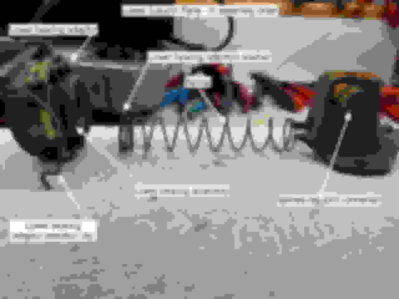
Here are the parts in order from left to right. Left= column top, right= column bottom Clean the plastic adaptor by hand. Dunk the rest in evaporust and carb cleaner.
Once the bottom of the column is off, you can turn to the top of the column. The first thing you'll see is the actuator housing which can be identified by the 2 big tilt return springs. Remove those springs with a tool, pliers or a screwdriver as you see fit. The easiest way to fiddle with them is if the housing is in its upmost position. Remove the springs. If they're crusty, dump 'em in carb cleaner for a while.
Next up, it's time to remove the pivot pins on either side of the column at 3:00 and 9:00 you have the column oriented to vertical in your vise. On one column I just tapped them out, on the other I had to make a little puller out of a #8 32 screw and a few nuts.
If you're lucky, these pins may just tap out with a screw, vise grips and rubber hammer.
If you're unlucky, the pins have been stuck in there for 55 years and you'll need a puller. Here's what I made: Cheap pivot pin puller. Take that Kent-Moore tools!
Since we're working on pulling the actuator housing off the column, you'll need to stick the tilt lever back on and hold it back towards you to release the pivot lock shoes to remove the housing. It's a pain, but it beats removing the shoes. They're spring loaded and very difficult to put back in. I'll never pull them off again. Just shoot 'em with oil and let them be. The tilt lever is missing in this photo, but you'll need it to release the locking shoes as you pull the housing back. It should slip just a bit until the upper bearing race seat stops it.
Now get your rubber hammer and tap the steering shaft out of the actuator housing so that it slips off. Don't lose the upper bearing race seat or the upper bearing race. They'll come off somewhere when the housing is released from the shaft. I call it a steering shaft, the factory calls it an upper yoke + lower yoke and shaft. I hope that's not confusing.
To allow the tilt feature, the actuator housing pivots up & down on a centering sphere. That way you can unsafely tilt the wheel when turning! Here's what that sphere looks like at home behind the actuator housing. The centering sphere is really 2 hemispheres with a hole in the middle holding a spring which makes electrical contact to ground the shaft for the horn. The spring is held in by a steel stop.
Let's stop there so I don't lose this content. Coming up, the trials and tribulations of the lock plate and shift tube!
Disassembly 2: Into The Shift Bowl
I figured it might be helpful for future reference and questions to spread instructions across a few different posts rather than 1 monster.
By now the lower column parts should be soaking in carb cleaner and the actuator housing and its bearing assemblies should be set aside for cleaning. Also set aside the still-assembled steering shaft. There's a bit to that shaft which needs it own disassembly instructions.
The next step on the column is to remove the shift lever bowl. It's pretty easy to find since the shift lever is on it. Also it's just 4 bolts to remove. It's also the thing that the pivot pins are pinned into. Anyway here's a shot looking down-column: Remove these 4 bolts to get at the lock plate. That plate holds the shift bowl to the column jacket (aka the outer tube).
Once it's out you'll see the lock plate, retained onto the shifter tube by a retaining ring which may be dirty and hard to distinguish. The stuff under the cast housing looks like this: Gently pop the retaining ring off the shift tube slots and the lock plate will come free.
The lock plate assembly has a few parts to keep straight. Here they are in order left to right - column-top to column bottom: Retaining ring, then washer, then lock plate, lowest is the wave washer. It's a little tricky to reassembled but taking it apart is quick.
Next rotate the shift tube from the bottom so that the steel connector to the transmission is in its lowest position. Then slide the shift tube out, or gently knock on the steel ear to pull it out of the column jacket. That arm one the right is much thicker steel than the thin metal of the tube, so don't knock the top of the tube if you can avoid it.
The top of the shift tube is carefully machined. If you need to use force, use it on this ear.
Since there are bunch of parts to the lock plate, I took a shot to show where and what order they go in on the shift tube: Before putting this tube back in, lubricate the section indicated here and the lock plate will go back on much more easily.
So now you have an empty column jacket. Degrease, sand and paint it if you like. Or just put it aside. There's work to do on the upper column parts. I made an Evaporust bath for my long parts out of a PVC tube with one end sealed - works well for de-rusting crusty parts: Evaporust takes a while. Best to submerge parts completely for 12-24 hours to achieve a consistent rust-minimized finish.
Let's stop there and get back to the upper column in the next post. There's a lot to discuss up there.
Disassembly 3: Return To The Upper Column
At this point you should have a bunch of parts from the upper column set aside - chiefly the steering shaft & the actuator housing. These are somewhat intricate so I wanted to spend some time focused on them.
Actuator Housing
The actuator housing is where the upper and middle bearings (really bearing assemblies) live. Also it's where the pivoting mechanism lives. Also it's where the telescoping parts live. The first thing to do is capture and set aside the upper and middle bearing so they can be cleaned and regreased. They are located on the top and bottom of the housing as shown here: Remove the upper and lower bearings for cleaning & regreasing. See my post above about how to clean and regrease. Don't lose any of the ball bearings.
Here are some views which will help you find the upper and middle bearings: After the bearings are removed, dunk this whole thing in carb cleaner for a while.
There's another bearing identical to the upper bearing hiding on the underside of the inside of this housing. Here's where to find it: Remove the middle bearing and set it aside for cleaning. It rides againt the race on the upper yoke. I left the race in place on the yoke and just greased it up.
I've probably said this too much, but leave the lock shoes in place. They're spring loaded and very difficult to get back into place since the springs are strong. Just grease/oil their pivot pins and be done. Don't fuss with the tilt lever or its pins either. Shoot 'em with oil if you like.
Upper Yoke + Lower Shaft & Yoke Assembly (aka the steering shaft)
You'll see the basic design from the CSM diagram above. Here's what it looks like once it's out of the column: It's been living in grease for over 50 years. Let's clean and regrease it for the next 50.
There's a factory process for separating the upper and lower shafts. You orient the upper shaft as shown here, then turn the lower shaft vertical to 90� and slip it upwards. Here's how that looks: The lower shaft spins on the sphere to allow removal.
And once the lower shaft is released: Lower shaft free of the centering sphere
There's a pesky little spring inside the sphere which sends ground up the column for the horn. Sometimes it bends. In the case of my second column the stop that holds it in place was bent. Once the lower column is off, you should see it inside the sphere. Or it sprung out, in which case you'll need to look for it...
Here's where I wound up. Lucky to have a few spare parts from looted columns from over the years. Good vs. bent spring stops. I put the good one back in, but saved the bent one.
Once the shafts are apart, you can separate the parts for different cleaning and servicing processes. I hand cleaned the sphere, but dunked the lower shaft in evaporust to clean it up. Expect to find the hardened steel surfaces of the inside of the yokes to be scratched. Upper yoke on the left, lower yoke and shaft on the right. These are high quality machined parts.
That's about it for the steering shaft. Let's look at the upper shaft that rides inside the yoke.
Upper Shaft (aka the telescoping rod)
This is the part that slides back and allows the wheel to telescope. It's actually a tube unto itself with another rod inside. On the bench it looks like this: Dunk the whole lot in carb cleaner, then grease the wedge & bumper in their slot.
I had trouble with my second column and got the orientation of the upper bumper wrong. When I tested it, it just wouldn't lock the shaft. Eventually I turned it around and it worked right. Point is - unit test the assemblies along the way until you have them working correctly.
I think that's about it for disassembly. I'll do something short on cleaning coming up.
Hope I'm not boring you all. These are at least partially notes to future me when I find time to go through to columns that are actually on my cars.
Cleaning off 50 years of Grease, Dirt and Rust
Let's start with off a nod to the engineers. These things work well even when dirty, rusty or or worse. That is to say they continue to work when neglected for decades. Well done Saginaw.
The parts on the engine side of the firewall take a beating from water, heat, rust, far flung dirt and oil. The interior parts live a much easier life cosseted in a closed, water-sealed cabin and are usually in much better shape. Expect if you pull the column from a convertible. Usually by the time a convertible hits the boneyard, the interiors are beaten past death into foam and dust. That's why I generally prefer (if possible) to pull from hardtop coupes and sedans.
My real goal here for the whole job was to remove old dirt & dried grease and leave well made parts in a nice coating of fresh new grease to improve the smoothness of the steering, shifting, tilt and telescoping processes. And I've been curious about these columns for 40 years or so.
As noted here & there above, I cleaned the metal parts in a 1 gallon can of Berryman's carb cleaner - mainly to soften or remove old grease. For rusty parts, or really dirty parts I submerged them in a solution of Evaporust.
I really should have left them in Evaporust for a day or more, but I got where I wanted to go with a little periodic brushing in 4 or 5 hours. Here's the small parts bath using a plastic shoe box: I don't want to sound like a shill for this stuff, but it works. There are probably chemically similar cheaper unbranded solutions, but I'm happy it works at passive rust removal. Not as fast as carb cleaner for grease, but just as effective at removing rust.
I hand cleaned the plastic parts with B12 chemtool spray on a paper towel to get the degreasing effect without solving the nylon or plastic into goo.
For further detail on cleaning and regreasing the upper and middle bearings see the out-of-order post above. Next up, I'll detail restoration of the lower bearing.
Every 50 years, be nice to your lower column bearing
Up above I detailed my procedures to clean and regrease the upper and middle bearings. The lower bearing is a different animal, though the cleaning & servicing procedures are basically the same.
Design & Purpose
The lower bearing is designed to center the lower end of the steering shaft inside a column adaptor so there's a straight line between the steering wheel and the steering box. This helps create a smooth rotational axis for the the steering wheel. The bearing sits inside a plastic column adaptor with the small diameter side facing column-up and the large diameter side facing column-down with the whole thing supported by a load-leveling washer pushed upward by a spring between the bearing and a spring tensioner. The upward spring force on the steering shaft helps suspend it in the upper & middle bearings again for smooth rotation.
Lower Column Bearing In Situ
Here's where the bearing lives. It's the metal part left the washer and right of the plastic adaptor ring The lower bearing lives in a spring loaded sandwich exposed to the elements in your engine compartment.
Let's pull it apart
At the bottom of the clip is a retention clip that holds a felt washer which forces the lower bearing retainer onto the bearing race. The race is placed small diameter side column-up.
Bend one leg of the retention clip and rotate it out of the lower bearing race. It'll come apart in an instant.
Here are the component parts of the bearing. Sorry to be inconsistent, but this time column-bottom is on the left and column-top is on the right. When you disassemble it, do it in a plastic box or other container to contain the bearings. Don't lose any of the 23 tiny ball bearings. The CSM calls this a bearing. I think of it as a "bearing assembly" since it's multiple parts working together as a bearing. I figure Olds didn't think anyone would break down the components to service them. In 1968, you would have just ordered a new bearing. But you can't do that now...
The game on servicing this is to polish the bearing race surfaces to get rid of any old grease or scratches. I do this with a combination of Berryman's B12 chemtool and a Dremel with a wire wheel. I also drop the 23 bearings into an old pill bottle with about 1/2" of carb cleaner to degrease the ball bearings. Shake well, then serve the ball bearings up on a paper towel and count them. There should be 23.
Next apply a coating of thick grease to the lowest ring of the lower bearing race and stick the ball bearings to that coating in as clean a line as you can manage around the ring void. Once you stick the lower bearing retainer back in, it'll force the ball bearings into a clean line and you're back in business. Then add the felt washer on top and look for the pattern left by the retention clip pins to figure out which way was up. Put it back as it was and snap the retention clip back in.
Lastly shoot some oil into the gap on the small diameter side of the bearing race to thin the grease which was sticking the ball bearings to the race. If the retainer is back in, put the bearing on your finger and spin it. If it spins smoothly you're done. If not, figure out what's hanging it up and smooth that out.
Based on the inner diameter and outer diameter of my lower column bearings, I've ordered some early corvette lower column bearing. I don't know if they'll fit yet since they have not arrived. But even if they don't fit, I'll bet the ball bearings inside are the same size...
The Trim repaint Detour
I thought I'd try my hand at refinishing the visible black trim parts just since I had it apart. I degreased & sanded a little half heartedly, shot it in my driveway with a ladder & coat hangers as my "paint booth".
Unsurprisingly, the shift lever bowl and actuator cover didn't come out all that great. They look o.k., but next time I pull it apart I'm sending the parts to a body shop for a proper respray. I just don't have the patience. Getting that factory look is something I'm better off leaving to professionals.
It reminded me when I was a kid building model airplanes and I'd smear the paint just to see what they looked like assembled.