When you click on links to various merchants on this site and make a purchase, this can result in this site earning a commission. Affiliate programs and affiliations include, but are not limited to, the eBay Partner Network.
First let me say that I am trying to understand the schematic symbols. This started as I was trying to do continuity test on my dash switches before putting them back in. I was working on the wiper switch, and have a couple of things I do not understand.
Second, I grabbed my CSM looked at the schematic, tried doing some internet searches but still I am confused.
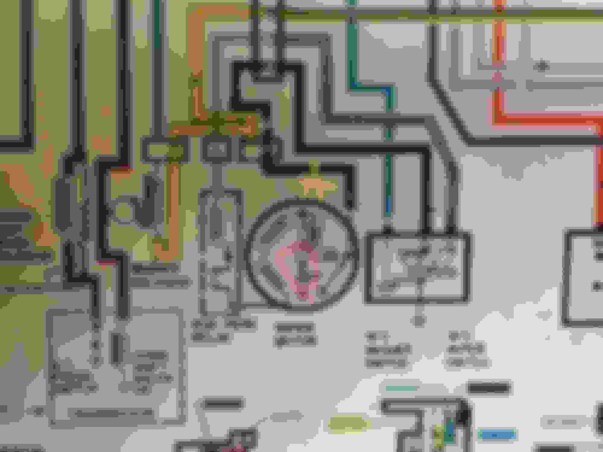
Here is the pic of the CSM page.
Here is what I think I understand. Switch power comes into the motor by the yellow wire at connection point A. The switch provides grounds to the circuits baed on the position of the switch. On low, the switch provides a ground to connection point on the right of the motor. On high, ground is both on the right side of the motor and flowing through to the run park relay. What I am struggling with is the paths. Part of this is that I am not following this symbology within the motor itself, nor the relay.
Can someone point me in the right direction of some of the symbols, particularly in the center of the motor?
Troy, you don't have to worry about the schematic inside the motor. Those are inductors and a resistor. All you need to confirm is that your motor has 12V on one side and a good connection to ground on the other side. Use a test light or multimeter to look for 12V with your wipers turned on.
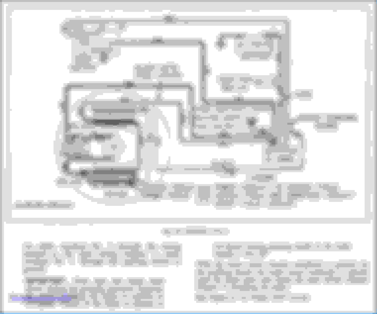
The circled area with the "CB" stands for circuit breaker, it self resetting. Here is a diagram that better explains it. Picture of the switch is a slider type and basically when both your black and lt blue wires are connected through the switch the motor is in low speed. With only the black connected your in high speed. The park switch mechanism is a latching relay to hold ground when the switch is selected off until the transmission gets to a certain point and the contact opens and the motor stops in the park position.
I appreciate that statement and is what I would typically do. I have usually steered clear of schematics, but this is more of an opportunity to learn for me.
I understand the looped lines in the motor is inductors and resistors.
As I was testing continuity in the washer pump switch. The high side some what confused me. Why was it sending two separate ground paths lug 2 & 3?
On the low position, I kinda see the circuit, if power is at connection point A (top of motor) then the circuit is the two inductors to the right. I don�t understand why it is again grounded to the case of the motor also.
On the high side, I am totally lost. The low circuit is still closed, as the switch touches both the second and the third lug. However, the 3rd lug provides ground through a relay (on the rest relay box. My understanding is that I am only looking at part of the relay box as it has dotted lines) to the left side of the motor, which would seem to be �powered� by the same connection point A already.
Thanks Eric, that helps a little let me digest that diagram. I thought it might be a circuit breaker. You have no idea how many symbols I have looked at and not come up with that one.
I trying not to ask too many uniformed questions, but I probably will before I completely understand.
I appreciate that statement and is what I would typically do. I have usually steered clear of schematics, but this is more of an opportunity to learn for me.
I understand the looped lines in the motor is inductors and resistors.
As I was testing continuity in the washer pump switch. The high side some what confused me. Why was it sending two separate ground paths lug 2 & 3?
On the low position, I kinda see the circuit, if power is at connection point A (top of motor) then the circuit is the two inductors to the right. I don�t understand why it is again grounded to the case of the motor also.
On the high side, I am totally lost. The low circuit is still closed, as the switch touches both the second and the third lug. However, the 3rd lug provides ground through a relay (on the rest relay box. My understanding is that I am only looking at part of the relay box as it has dotted lines) to the left side of the motor, which would seem to be �powered� by the same connection point A already.
Just trying to to understand a little more.
I explained in a little more detail in my previous post after yo posted this. The reason why you see continuity is because you measuring through a coil and a resistor to ground. It doesn't tell you anything other than your circuit is not open.
I explained in a little more detail in my previous post after yo posted this. The reason why you see continuity is because you measuring through a coil and a resistor to ground. It doesn't tell you anything other than your circuit is not open.
I think both of our previous posts crossed. The beginning of the reply where I stated that �I appreciate that statement� was meant for Olds64. I want to try and clarify one thing though. The only continuity testing I did was on the wiper/washer switch itself. Wiper motor is down on the shelf in basement, and the car is almost 5 hours away. I am not chasing a short, but trying to learn a little about schematics.
Eric, I appreciated your earlier post an I am still digesting that diagram. I am reviewing information on dc motors now.
With that said let me start over with what I did in the next post.
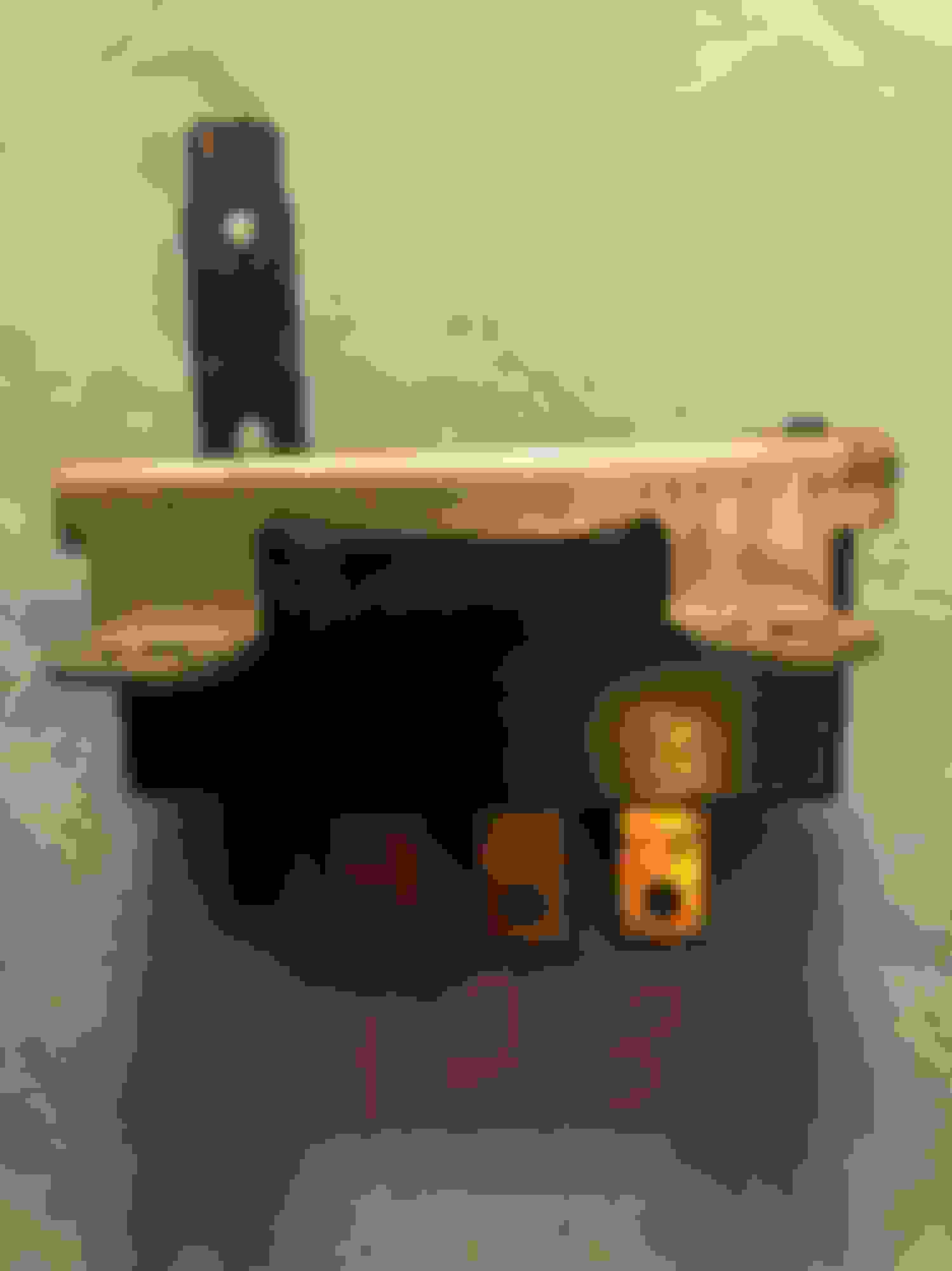
So I started by testing continuity on the wiper/washer switch.
By testing continuity from the switch body to the lugs on the switch as designated below.
Lug 1 only has continuity when the wash button is pushed.
Off position- Lug 2 has continuity
Low- Lug 2 and Lug 3 have continuity
High- Lug 3 has continuity
Then the question of how do I know if this is correct, and I went to CSM to look at the schematic. By the switch diagram in the schematic switch looks good. However, that then had me trying to follow the circuits through the motor and hence the questions.

 July 18th, 2018, 03:03 PM