When you click on links to various merchants on this site and make a purchase, this can result in this site earning a commission. Affiliate programs and affiliations include, but are not limited to, the eBay Partner Network.
Jimmy, I'm not a fan of the paper door sheets, and I only use plastic now (for obvious reasons). I know when I did my GS 5-6 years ago, I tucked the bottom into the slot, so that if any water got between the panel and sheet, it would be deflected back inside the door to drain out the drains. It's the bottom of the panels that always warps from moisure. I think all my cars are tucked like that, and I thought that's the way they came. One of the big shows I go to is rain or shine, it's like 125 miles one way. I drive, it always rains! The panel screws I put them in a bit, hang the panel kind of aligning it, then get down under the door and use a small pick to make the holes. That way you can see to line them straight. The replacement panels with the rug are probably more durable there. You put all the clips, on all the handles, one way. There's only one right way, although they go either way. Then, when you remove them, you know which way to use the tool.
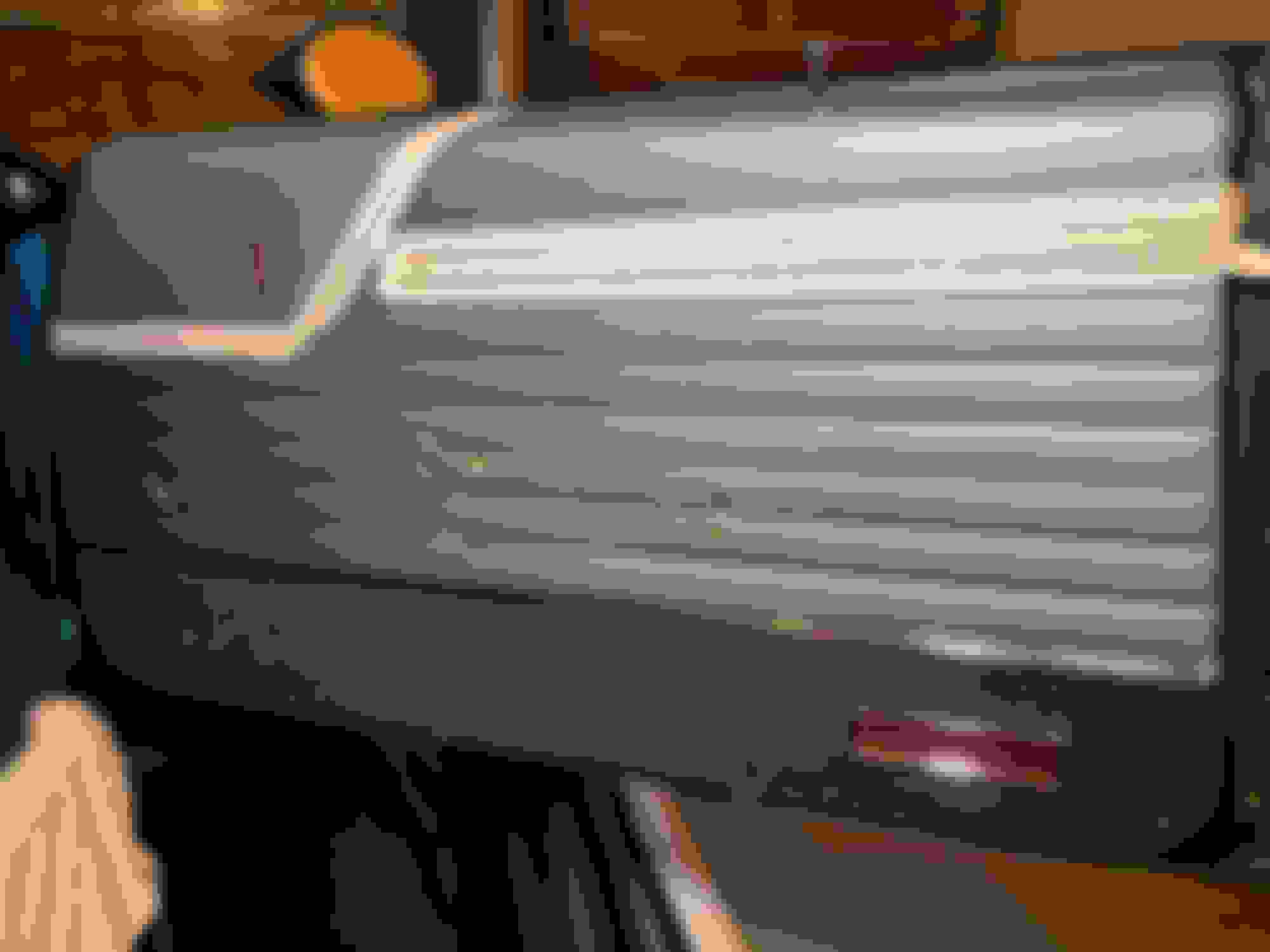
It was rainy today so I had to pick a project I could knock out in the garage which meant the carpet will have to wait. Instead, I worked on the RH door splash shield and door panel.
The splash shields from REM fit quite nicely. I lined the door where the edge of the shield would hit with Butyl sealing tape, lined up the shield, and pushed the paper down on to the sealant. This is as close as I could get to the factory with what I have access to. After, I used a perfect match to the factory tape (even down to the width!) and taped the shield in the exact places observed during disassembly.
I mocked up the door panel and I think it�ll fit okay. The six prongs for the back were a pain in the *** to slide in to the panel. I also need to come up with a way to mark the back of the panel for the four screws on the carpeted portion towards the bottom. I am thinking of using rivets in the holes, pushed the panel against them to get an indentation in the cardboard, and then using a fine tip on a soldering iron to poke through. Anyone have another approach?
I carefully removed the LAN10 body tags before ripping the car apart. I replaced them back in the same spot and angle as removed. There�s a little white lithium grease build up at the bottom of the door as I soaked the window mechanicals.
Splash shield in place.
Tape in same spots as the factory.
I bought this tape off Amazon. I would recommend it.
I picked up this butyl sealing tape off Amazon, too.
I am already having nightmares about putting the c-clips in place for the crank and door pull! Does anyone know the �factory� positioning of the window crank for a rolled up window?
I spent time �massaging� the panel for the RH door today to get a better fit. I am still not happy with it. The fit at the front is tight. With the kick panel installed, it�ll be rubbing for sure. Anyone have a sure fire way to shift the panel back about an 1/8�?
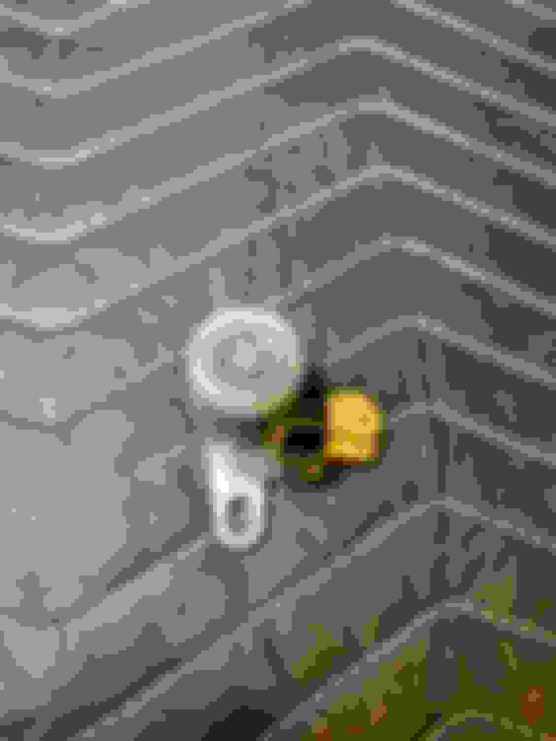
I also wanted to include pics for how I did the screw holes for the bottom. I put small rivets in to the four holes with the short part of the rivet sticking out. With the panel mounted, minus the bottom clip on each side, I pushed the panel against the rivets to make an imprint in the vinyl / cardboard. I preheated the solder iron to 450 degrees and went right through from the back. It worked out really well and cauterized the carpet so it would unravel.
Looking for tips to �shift� the panel. Block of wood and a tap? The factory panel just fits so perfectly it�s not even funny.
Small rivet placed loosely in the door.
To get the rivet straight, I used thin needle nose pliers and then applied pressure to the panel.
In this instance, the rivet actually stuck to the back of the panel which was better than expected.
Changed to a finer tip on the soldering iron.
The cardboard was no match for 450 degrees.
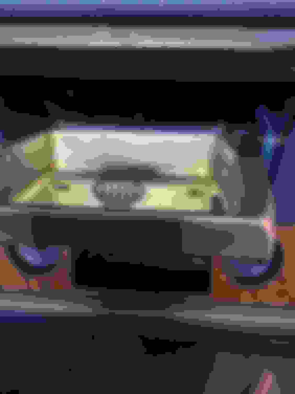
Panel installed. This was after a few hours of playing with the fitment.
With the door closed, this is how tight the panel is near the kick panel. I can get a piece of paper between the panel and the metal which tells me it�ll rub with the kick panel installed.
This was a close friend's GSX car. They docked him for it. Look closely at post #170, then move forehead closely to wall back and forth several times. Legendary, "simply the best"!
Before you cut, you can try moving the brackets at the top of the door. The front looks a bit high, and the back a bit low. Moving the front bracket in or out, can make a difference in the fit. When you look at the fuzzies, they should be like parallel. Be sure to move the window up and down, as you test fit.
Before you cut, you can try moving the brackets at the top of the door. The front looks a bit high, and the back a bit low. Moving the front bracket in or out, can make a difference in the fit. When you look at the fuzzies, they should be like parallel. Be sure to move the window up and down, as you test fit.
Good eye. I went and looked after reading your note. The front is very high and the rear is very low. Have I mentioned how much I dislike the interior reassembly so far?
Looks like I will be working the panel this week for a better fit!
Having an issue with the LH side glass in the door. When I crank the window down, it makes this god awful noise. I lubed all the areas that looked like they needed it but the noises still remain. I’m thinking it’s the fuzzies or too much tension somewhere. Thoughts on where to start to make this better?
Warning: turn down your volume a bit and hide your pets because the noise is terrible.
The RH door had a floppy lock situation going on. I�d push down or pull up on the lock pull and it felt like nothing was really happening. I pulled back the splash shield and did a comparison to the LH door and noticed the white plastic clips that hold the rod were way off. I hit them with a tiny bit of grease and used a flat edge to push them back in to their respective locations. Problem solved...hope this also solves my door lock issue with the key.
Hope you got rid of that terrible noise with the door glass Jimmy. Had the same problem myself and eventually pinpointed it coming from the felt covered adjusters at each end of the glass on the inside when there was a bit too much pressure on the glass. I'm enjoying your journey with this resto and it's very inspirational. Keep up the great work - the finish line is in sight.
Hope you got rid of that terrible noise with the door glass Jimmy. Had the same problem myself and eventually pinpointed it coming from the felt covered adjusters at each end of the glass on the inside when there was a bit too much pressure on the glass. I'm enjoying your journey with this resto and it's very inspirational. Keep up the great work - the finish line is in sight.
Thanks, Rohan. What did you end up doing to get rid of the noise?
Spent another two hours massaging the RH front panel. I even mounted it with the bracket closest to the hinges off to see if the front would come down a bit but it didn�t. Then I thought maybe the issue was the door seal but that is pretty thin considering it�s 40+ years old. I worked the brackets and the clips to get the side closest to the rear up a bit so it sits almost parallel. From the outside, I don�t love that the staples for the inner seal to the panel itself are visible. Oh, Legendary...and on that topic, I have been going back and forth with their technical resource (whom have actually been helpful) on what happened to the LH panel to create those waves.
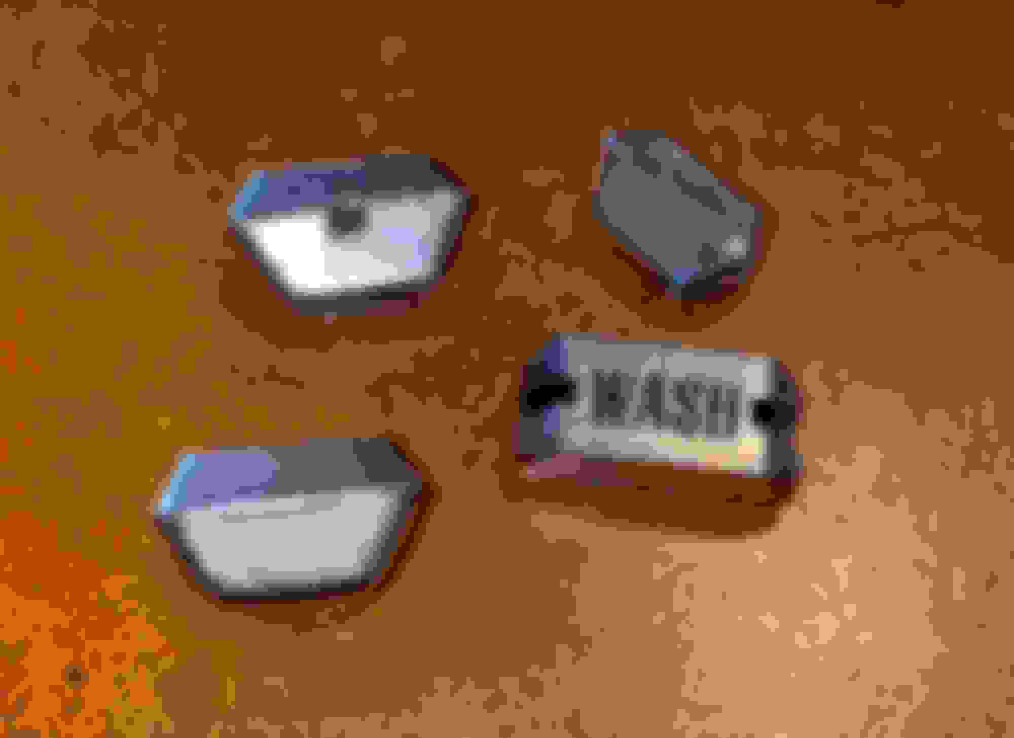
I also worked on the control ***** for the dash yesterday. I cleaned them, gave them a polish, and then redid the black detail. I used a Testors pen and carefully wiped off any excess.
Before with oxidation and 50 years of gunk:
After:
Last edited by WTHIRTY1; Nov 19, 2020 at 06:32 AM.
Thanks, Rohan. What did you end up doing to get rid of the noise?
Jimmy I just backed off a little bit of pressure from those felt covered guides at the font and back of the door and hey presto the squealing noise was gone. Let me know if you're still having dramas and I'll give you a call.
Jimmy I just backed off a little bit of pressure from those felt covered guides at the font and back of the door and hey presto the squealing noise was gone. Let me know if you're still having dramas and I'll give you a call.
Yes, give me a call next week. I�ll send you my cell via Facebook. Thanks, Rohan!
Trying to clean out parts inside the house so today I had the original Goodyear mounted to the factory SS2 wheel. I used the correct NOS 274083 1 1/4� straight stem for 29/64� hole. With the tire mounted, I can at least get the trunk completed so more parts are leaving the house and actually going in to the car. The wife will approve!
These wheels were matched to an original spare I have from one of my cars that had never been used. I need to install the bezels this weekend along with the cap. The original bolts for the caps were all rephosohated and came out like new.
Worked a bit on the interior while I watched the MCACN 2020 virtual feed from the Brothers Collection. Unreal cars!!!
I think I worked out my door panel spacing issue as best as I could. I measured the new panel, and it�s a little wider than the factory�no surprise. But it looks much better now.
I pulled out some NOS window cranks, door pulls, and plastic �bushings� for the doors. I had previously detailed the spring for the window crank...had to pull out the Fisher Body manual so I could remember how the spring went!
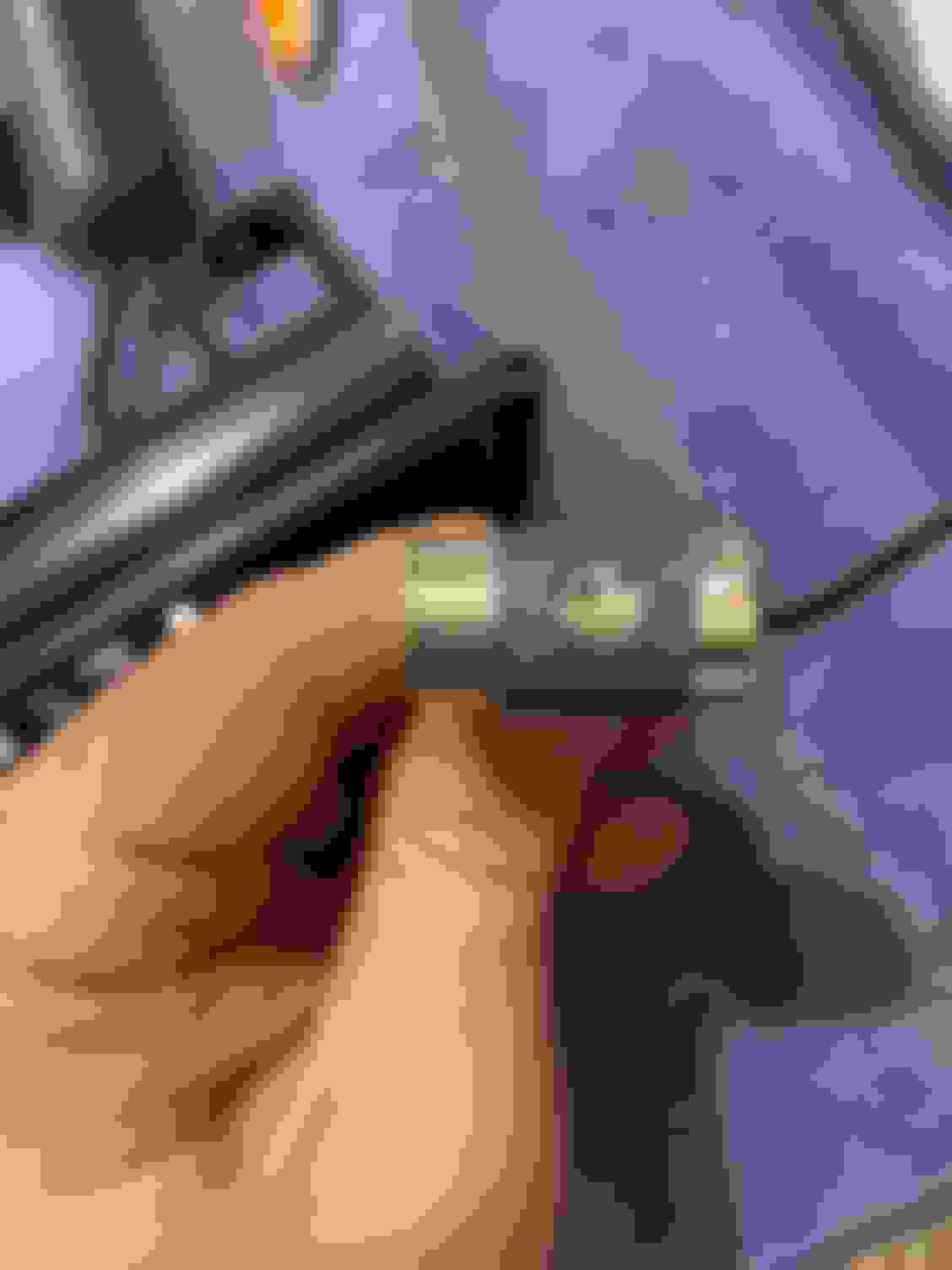
It has been awhile but almost feels as though something is missing with the door pull. Or am I just imaging things here? The C clip is on and the handle is tight.
As for the arm rest bases, the RH side has one long screw and two shorter screws. Which of the three holes gets the longer screw? Ironically, the three screws for the LH base are all the longer ones.
Few goodies that have been stashed away for almost three years now.
It seems odd how the C clip is hitting the panel like that, no? The blue tape is just there to protect the panel from the tool.
Clearing out some parts that were in the interior bin.
Back at it again with the RH door panel. Two things that suck. The arm rest base when installed in the factory holes leaves about 1/8� of an opening from the hole in the panel. It�s not very noticeable but it�s driving me nuts. The other thing is that the base, though level, has uneven sides with the seam. I think I�m going to rest I�ll three new holes and see if I can�t solve both issues.
I tried massaging the base to get this corrected but once the screws bite the holes the base locks in to place.
While the base is actually level, it isn�t level with the seam.
The level of the seam.
I had to go back and reference the original door panel. The base is level with the seam.
Had to take measurements just to see how off I am.
On the plus side, the crank went on in the position I wanted without any issues.
I have a feeling that a union guy on the assembly line, especially in 1970, wouldn't have thought twice about this. He'd just have had another sip out of his flask and moved to the next car! Perfection wasn't the driving force as I see it.
I have a feeling that a union guy on the assembly line, especially in 1970, wouldn't have thought twice about this. He'd just have had another sip out of his flask and moved to the next car! Perfection wasn't the driving force as I see it.
I agree BUT since I can see how it was on the factory panel I would imagine that same Union worker became pretty good at putting in 3 screws 600 times a day ha
I spent some more time on the interior of the car tonight. It may seem like I�m jumping around a bit on the interior, which I am, and that is because I didn�t do the disassembly myself. I probably spend half my time just studying the wires, ducting, etc. and little time wrenching.
A few random questions I need help with.
1.) On the main harness, there is a plastic piece that has two holes and appears to attach near the fuse box. Where exactly does it attach and what do the two screws look like? I have a bag with two really tiny screws along with the high beam switch hardware, and I�m wondering if this is what they�re fit.
2.) Is there a way to disassemble the high beam switch to get the top �cap� off so I can clean it and plate it?
Tonight I reassembled the accelerator pedal arm and bushing and bolted it to the floor. The rest of my night consisted of installing a new / used vent for the front defogger and detailing the fuse box. I need to see if an emory board will clean up the prongs for the fuses. Thoughts?
All factory OE pieces used here with the exception of an NOS pedal. I know a lot of guys will paint the bare parts here, but I opted to oil them really well and maintain that natural finish. I�ll likely kick myself for that when these parts start to flash rust.
Original spring refurbished.
Dab of grease between the arm and the plastic bushing.
I would like to reuse this as it still works. I have seen guys remove the top part. How is it done??
Took another pass at the arm rest base. It�s much better now. I put the screws in without the base and pulled on each one using a screw driver as leverage. I installed the far right screw first and inches the other two screws in a few turns each time alternating.
Maybe this will help Jimmy. The screws were pretty rusty so Im thinking they were raw or not plated with much protection. I dont have a pic of those after removed. This is where it was installed.Pics aren't the best but hopefully you get the idea.
Don't lose that plastic piece! The harness should loop up and back down through that plastic shroud. It's been awhile but I believe two of the screws that hold the fuse box to the firewall capture that shroud. You can see that in the photos above.
Maybe this will help Jimmy. The screws were pretty rusty so Im thinking they were raw or not plated with much protection. I dont have a pic of those after removed. This is where it was installed.Pics aren't the best but hopefully you get the idea.
Thanks, Paul! So did the harness also go through that black clip? What's the metal piece to the right of the clip?
I dont believe it went through the black tie. The piece to the right is plastic and I believe it is was wrapped into another harness for routing. I will look more into some of my pics.
I dont believe it went through the black tie. The piece to the right is plastic and I believe it is was wrapped into another harness for routing. I will look more into some of my pics.
I dont believe it went through the black tie. The piece to the right is plastic and I believe it is was wrapped into another harness for routing. I will look more into some of my pics.
Reviewing the PIM tonight. Looks like the tan wire for the e-brake goes through the black strap.
EDIT: Reading through more of the PIM, that 406540 part number is the same strap used on the valve cover. Good to know.
Last edited by WTHIRTY1; Nov 24, 2020 at 07:21 PM.
You can take the switch apart, I had mine apart. But I don�t know if the top cap comes off. It looks like it�s pressed on and smashed, by looking at the top of the cap. I have a couple extra ones I can try to take apart and see.
Gearing up for Thanksgiving and getting ready to shut the engines down for the week. Last bit of detail work going in to the dash for tonight.
I had this capacitor hanging down from the dash that kept smacking me in the face while I was trying to work. I disconnected the harness and took the capacitor out of its bracket. The bracket is a beautiful galvanized steel. The capacitor appears to be original and even has a date stamp on it! I cleaned it up with 0000 steel wool and carefully avoided the numbers. I also found the illustration in the PIM and the correct screw in a bag of misfit dash hardware.
Cool date code.
Cleaned up.
I�ll mount it like this so the numbers are visible.
And one final question. What is the best way to open this clip for the detent cable? I can�t seem to get it to open wide enough to go over the thicker parts of the cable.
Reviewing the PIM tonight. Looks like the tan wire for the e-brake goes through the black strap.
EDIT: Reading through more of the PIM, that 406540 part number is the same strap used on the valve cover. Good to know.
Yes that looks familiar. Im also leaning toward the other tab being being there and not being used for anything? If it had something attached I'm thinking I would have photographed it.
Yes that looks familiar. Im also leaning toward the other tab being being there and not being used for anything? If it had something attached I'm thinking I would have photographed it.
There is a small clip that is taped in to the harness with a little prong that pushes in to one of the holes next to the black strap. I was looking at my clip last night (of course, the prong is broken off). I’ll grab a picture later today.
Last edited by WTHIRTY1; Dec 17, 2020 at 07:39 AM.
This is overwhelming but refreshing at the same time. It's how it should be done. Did you use a Gardner exhaust system? Just a question i have a 68 442 conv and i am wondering if the front and rear sway bars were originally black or in plain steel if any one knows i would much appreciate you letting me know.