Wiring diagram
#1
Wiring diagram
I have both a CSM and a BSM for my 65 Cutlass but neither one has a wiring diagram. Where do I find one?
A previous owner messed around with the ignition wiring so that now the engine remains running if you quickly switch over to accessory. I also suspect that the resistance wire may be blown as there is a Chrysler style resister mounted to the firewall, however on closer inspection only one wire is connected to it, leading me to assume 12 volts are being supplied to the points all the time. I will check this out.
A previous owner messed around with the ignition wiring so that now the engine remains running if you quickly switch over to accessory. I also suspect that the resistance wire may be blown as there is a Chrysler style resister mounted to the firewall, however on closer inspection only one wire is connected to it, leading me to assume 12 volts are being supplied to the points all the time. I will check this out.
#2
A color wiring diagram should be in electrical section of the CSM and covers ignition electrical. Does it look like anyone has ripped out pages?
Body manual has line diagram for the body wiring (power windows, convertible top etc).
Body manual has line diagram for the body wiring (power windows, convertible top etc).
#8
Definitely some buggery going on, lol, and I find this stuff confusing enough without someone screwing with it.
I've discovered that that the wire going to the coil is connected to the power antenna plug on the fuse box. It looks like a Chryco style resister was connected between this wire and the coil, however it had been bypassed. Therefore I was getting full battery voltage to the coil and burnt points.
When I disconnected this wire from the coil and left the original wires connected I measured battery voltage (13.7) at the coil with key in ignition position. I think it should have been approx 7-8v right? If the resistance wire was faulty it should have infinite not zero resistance ?? Just spit balling, but is it possible that the coil is getting 12v from the solenoid even when it's not engaged?
#10
Basic Ohms law. You will see battery voltage at the coil wire without a load. Connect the power feed to the coil, and assuming the points are closed, you should see 7-8 volts. If the points are open, the meter will ready basically battery voltage.
#14
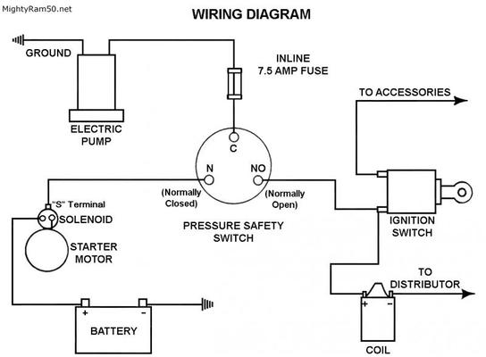
Donít wire an electric fuel pump to a ignition power source without some kind of safety switch! If your in an accident snd incapacitated, and canít switch off the ignition do you really want the fuel pump to stay running?!
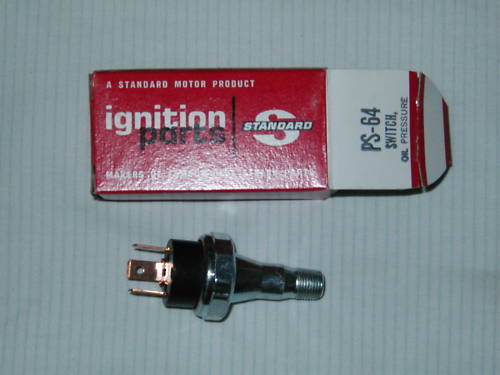
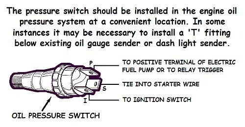
Look into something like this.
https://www.google.com/shopping/prod...:1,prmr:1,cs:1
Look into something like this.
https://www.google.com/shopping/prod...:1,prmr:1,cs:1
#16
Where is the best place to source a ignition on 12v to go to the oil pressure switch.
Matt your link quit working could you try reposting it, thx.
Matt your link quit working could you try reposting it, thx.
Last edited by Cutlass Fan; April 12th, 2021 at 05:29 PM.
#18
#19


#20
I’ve been using Joe’s solution in both of my big cars for years and it works well.
It works so well in fact, that I forgot I did it, and it took me 15-20 minutes to figure out why I didn’t have power after I blew a fuse one time. Heartily recommended.
If you do it, locate the fuse in an easy to replace location. Like _not_ under the J bypass hose, close to the oil pressure switch listed above.
Must get around to fixing that one day.
cf
Thread
Thread Starter
Forum
Replies
Last Post


