
wiring in a tach

Thread Starter
Registered User
Joined: Feb 2012
Posts: 537
From: Alberta
wiring in a tach .......UPDATE...FEB22
let me just say I know nothing about these old cars and am here to learn!!
I just purchased a 71 delta 88 and would like to ad a tach......so I did some reading and found some info that says it gets wired to the coil!!!
So here is my question...is this my coil.....as I said I know nothing about these old cars.....lol
DSC08138.jpg
I just purchased a 71 delta 88 and would like to ad a tach......so I did some reading and found some info that says it gets wired to the coil!!!
So here is my question...is this my coil.....as I said I know nothing about these old cars.....lol
DSC08138.jpg
Last edited by scooter123; Feb 22, 2012 at 07:22 PM.
Registered User
Joined: Feb 2010
Posts: 906
From: Windsor, Ontario
Hey scooter123: Search for a 1971 Oldsmobile Service Manual. http://www.faxonautoliterature.com/S...Manual&c=34442
It will save you lots of time and confussion!
It will save you lots of time and confussion!
Old(s) Fart
Joined: Mar 2007
Posts: 50,803
From: Northern VA
From the wiring on that coil, it looks like your car may have had an aftermarket Pertronix (or similar) electronic ignition added. I'm not sure if a generic tach will work properly. Verify that what you have before getting a tach. Note that the tach feed wire should run to the same side of the coil as the distributor, which should be the negative side of the coil.
Registered User
Joined: Aug 2006
Posts: 3,145
From: Far Northeast Philadelphia, PA
Yep, that's the coil. Tach goes to the neg side of that.
Usually 4 conection wires on a tach.
One to ing source, one to ground, one to lighting, and one to source (in this case neg on the coil)
The wire to ign, be sure to fuse it with either an inline glass type or a spade type. Should say in the tach instructions how many amps the fuse should be.
Also, if it's a "wire" type on the back of the tach, there should be no wires cut. Usually tachs are universal for every engine upto 8 cylinders and you cut wires on the back of the tach to make it read for a 4 or 6 cylinder. Newer ones have switches
Connoisseur d'Junque
Joined: Sep 2010
Posts: 21,183
From: The Hudson Valley
Scooter, as Jaybird says, please obtain and read a copy of the Chassis Service Manual.
Here is one for $32 on eBay.
Here is where you can download one for free (please register and join first).
The Chassis Service Manual tells you how the car works and how to fix it. If you really do "know nothing about... old cars," then the first and best place to learn is from the manual. You will do much better if you read the manual first, then come here to ask clarifying questions.
- Eric
Connoisseur d'Junque
Joined: Sep 2010
Posts: 21,183
From: The Hudson Valley
Of course, Joe, nit to be a buster, but if he's being accurate when he says he knows nothing about old cars, he needs to be told that to remove the cap he has to press the screws downward and rotate 180� to release the hooks, and he may not know what points look like.
Hence my honest suggestion that he do some independent study .
.
- Eric
Hence my honest suggestion that he do some independent study
.- Eric
Thread Starter
Registered User
Joined: Feb 2012
Posts: 537
From: Alberta
hahaha....I do know what points look like...I have rebuilt a few old early honda motorcycles which has a points system!!!
Im know stranger to the mechanical side of motorcycles but it my first stab at these old cars!!!!
I took a closer look at the plug wires and they say MSD......AND the little black box next to the coil is my voltage regulator...130v......Is this any indication what type of ignition I might have...without removing the dis/cap!!
Thanks for your help guys!!!
Thread Starter
Registered User
Joined: Feb 2012
Posts: 537
From: Alberta
Hey guys just giving you an update on this tach thing!!! I removed the distributor cap and found what looks to ba an electronic ignition upgrade!!!
So the instructions say " THIS TACH IS DESIGNED FOR USE ON DISTRIBUTORS EQUIPED WITH 12 VOLT NEGATIVE (-)GROUND, FOUR-CYCLE AUTOMOTIVE 4-6-8 CYLINDER ENGINES, AND IS NOT DESIGNED FOR USE ON A POSITIVE GROUND(+) ELECTRICAL SYSTEMS....INSTALLATION ON DISTRIBUTORLESS IGNITION SYSTEMS (DIS) IS NOT RECCOMENDED!!
So does this mean its no good for my car????
DSC08140.jpg
Connoisseur d'Junque
Joined: Sep 2010
Posts: 21,183
From: The Hudson Valley
I, for one, would like a better look at that module.
Could you pull the rotor and get a better picture?
Is there any label or marking on it?
Where do the wires go?
Most if not all of these will have instructions available that tell you where to connect a tach, but I would suggest that as a general rule, you connect the tach to the (-) coil terminal (the one that should go to the points, not the one that goes to the battery), as this connection should be cycled to ground, regardless of the electronic module used.
- Eric
Thread Starter
Registered User
Joined: Feb 2012
Posts: 537
From: Alberta
here is another pic of the distributor....hope this helps identfy if its electronic ignition or not......I realy dont want to remove anythinh else...im scared I will mess something up!!!lol
DSC08141.jpg
DSC08141.jpg
Connoisseur d'Junque
Joined: Sep 2010
Posts: 21,183
From: The Hudson Valley
Well, you've already got it working, so it doesn't matter now anyway.
No doubt that's an electronic module.
You can't mess anything up by taking off the rotor.
I am assuming that the stud and nut holding the rotor on are a regular MSD thing, and not just someone's hack job. If that's the case, that's an MSD distributor (not a GM one) that came out of the box with with an MSD module.
- Eric
Just an Olds Guy
Joined: Jul 2008
Posts: 24,528
From: Edmonton, AB. And "I am Can 'eh' jun - eh"
Well, you've already got it working, so it doesn't matter now anyway.
No doubt that's an electronic module.
You can't mess anything up by taking off the rotor.
I am assuming that the stud and nut holding the rotor on are a regular MSD thing, and not just someone's hack job. If that's the case, that's an MSD distributor (not a GM one) that came out of the box with with an MSD module.
- Eric
No doubt that's an electronic module.
You can't mess anything up by taking off the rotor.
I am assuming that the stud and nut holding the rotor on are a regular MSD thing, and not just someone's hack job. If that's the case, that's an MSD distributor (not a GM one) that came out of the box with with an MSD module.
- Eric

2-stroke 1-cylinder guy
Joined: Nov 2013
Posts: 333
From: Bavaria, Germany
Robbing a dead body here, sorry...
At the coil's + terminal, is this the famous shiny resistor nichrome wire in addition to the yellow 12V-when-cranking cable and the red Pertronix cable?
I'm still looking for a good pic of the resistor line to find it in my all-black sprayed engine bay...
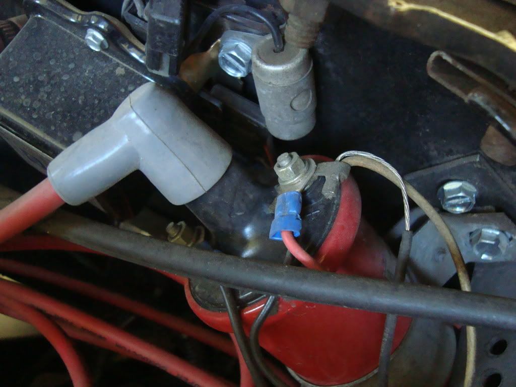
At the coil's + terminal, is this the famous shiny resistor nichrome wire in addition to the yellow 12V-when-cranking cable and the red Pertronix cable?
I'm still looking for a good pic of the resistor line to find it in my all-black sprayed engine bay...
Old(s) Fart
Joined: Mar 2007
Posts: 50,803
From: Northern VA
Robbing a dead body here, sorry...
At the coil's + terminal, is this the famous shiny resistor nichrome wire in addition to the yellow 12V-when-cranking cable and the red Pertronix cable?
I'm still looking for a good pic of the resistor line to find it in my all-black sprayed engine bay...
At the coil's + terminal, is this the famous shiny resistor nichrome wire in addition to the yellow 12V-when-cranking cable and the red Pertronix cable?
I'm still looking for a good pic of the resistor line to find it in my all-black sprayed engine bay...
Connoisseur d'Junque
Joined: Sep 2010
Posts: 21,183
From: The Hudson Valley
Joe, you misspoke.
With no load, and therefore no current flow, the voltage at the end of the resistor wire will be the same as the battery voltage. Voltage drop can only be measured under load.
So, do not disconnect the hot wire from the coil.
Instead, jump the (-) coil terminal to ground (in case the points are open) and test as Joe suggests.
And, Nop, yes that is the factory original coil terminal and wires. The factory terminal has a unique appearance.
- Eric
Old(s) Fart
Joined: Mar 2007
Posts: 50,803
From: Northern VA

Thread
Thread Starter
Forum
Replies
Last Post
RAMBOW
Major Builds & Projects
17
May 3, 2022 04:25 PM


