When you click on links to various merchants on this site and make a purchase, this can result in this site earning a commission. Affiliate programs and affiliations include, but are not limited to, the eBay Partner Network.
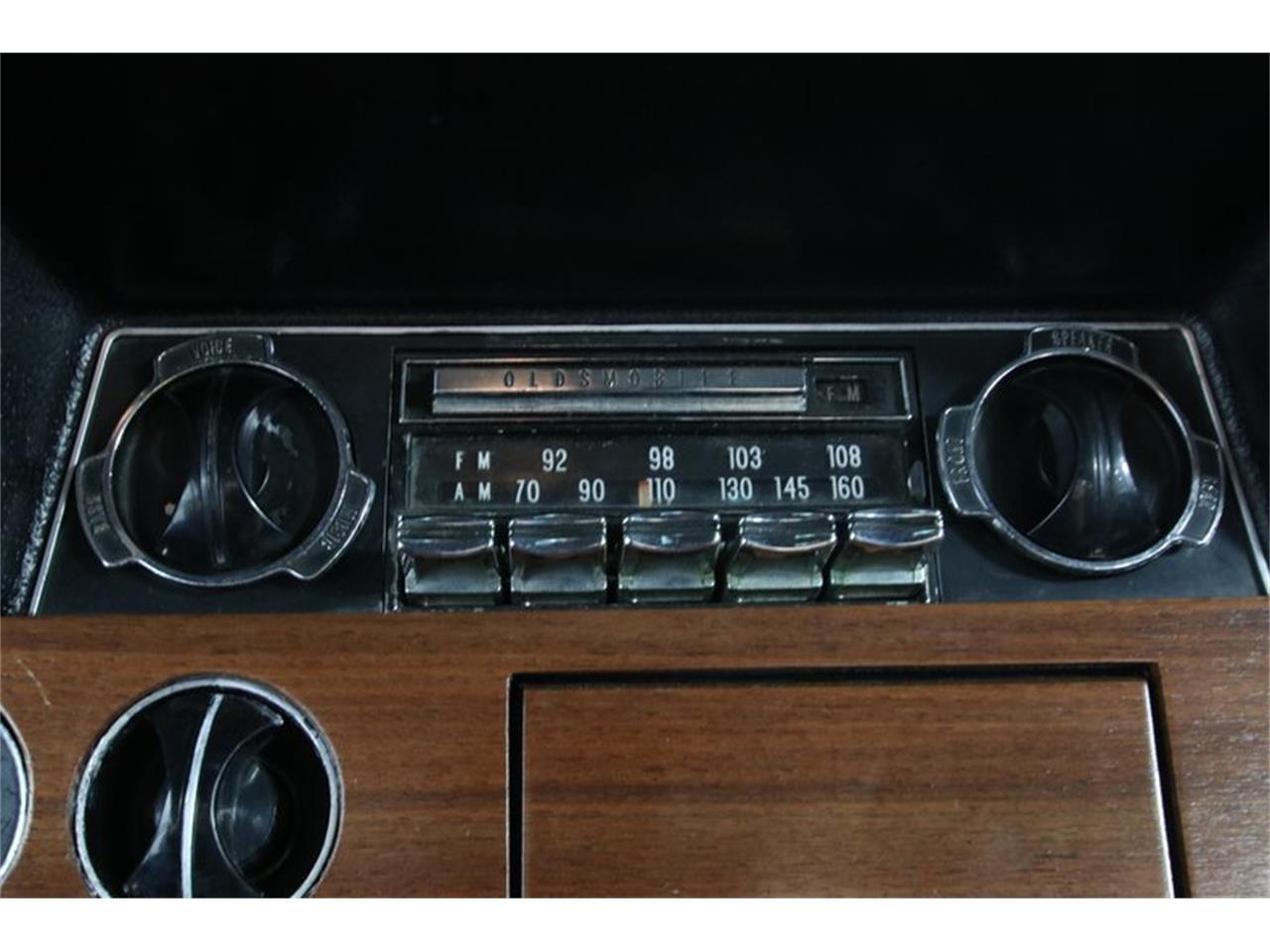
Can anyone tell me how to wire this old am radio for a 68 442. I�m going with just one speaker which has two wires. The back of the radio seen here has a tab for ground, one for speaker, and one that says 12 v (Which I assume goes to the ignition). Then there�s a blue wire with a plug out of the other side of the radio.
the antennae is obvious. Doesn�t the speaker need two wires?
Thanks �Billy
I believe one end of the speaker is connected to ground. One of the oddball wires is connected to the dash lights so that the radio dial lights up and dims w/ the dash lights. The 12V wire goes to the ACC circuit, not ignition, otherwise you won't be able to turn on the radio when the key is in the ACC position.
The blue wire is for the rear speaker. The front speaker has two wires to the plug, going to the radio. The plug has three positions, two for the speaker and a blank that the yellow wire plugs into, (12V). Make sure that the small metal link is inserted into the front of the radio, behind the tuning ****. There are three holes there with the upper two having the metal link.
I�m gonna try that wiring set up. Here�s a pic of the front and I think that link looks just you said. Here is a pic of the front. Does this look right? �Billy
Just to verify - the three spades from psngr side to driver side are: front speaker ground (black wire), front speaker positive (blue wire) and 12V power (yellow wire). The front speaker wire harness should have its two wires in a connector (black on the psngr side and blue in the middle) that has an open spot on the driver side. that connector plugs into the back of the radio and another connector that has the yellow wire plugs into the open driver side spot in the speaker connector. The separate blue wire you show looks like it goes to a rear speaker.
Thanks. There is no harness cuz there was a modern radio cd usb radio so all wires are separated and a mess. I�ll start by trying the yellow to 12v, speaker to SPKR spade and ground snd speaker to chassis. �Billy
If you want a rear speaker at a later date you would remove that link and install the fader control there. The fader has three pins and hook up the rear speaker to the blue wire.
If you want a rear speaker at a later date you would remove that link and install the fader control there. The fader has three pins and hook up the rear speaker to the blue wire.
Wouldn't the front/rear fader control have a 2nd, concentric shaft on that right side control (like what can be seen on the left side control in the photo) and be built into the radio (not really user-installable)? Or does it slip over the shaft somehow from the outside? It appears that while that radio has a blue wire for the rear speaker, there is no fader installed on it.
Also, I suspect that if a fader could be added to that radio, the outside **** would need to be changed as well so that it has the proper FRONT/BOTH/REAR markings (the outside **** on a non-rear-speaker radio is not marked as such).
Well looky there! A "bolt-on" mod for the factory radio! I've never seen one of those before. Mine didn't have the rear speaker, only a blank outer ****.
While that unit might work in a '68 radio, the **** design for the '68s are different than the '69-'72s (the '68 outer **** has 3 "tabs" that stick out beyond the OD of the **** with the appropriate words cast into the tabs. On a non-rear speaker radio like mine, the 3 tabs were blank.
I got my self a 10 ohm speaker and hooked it all up 12 volt power, spk to (+ ) on speaker. ( - ) on speaker to ground. Radio grounded. I get light in the radio but nothing to the speaker. And smell a burning though there isn�t much dust inside from what I can see. Anyone have any advice? �Billy
OK, seriously, Chapter 15 shows that BOTH wires from the front speaker plug into the back of the radio, to the LH two of the three spade terminals. The RH terminal of the three is power from the fuse box. The radio chassis bolts to the sheet metal ground strap on the back of the plastic dash to provide ground. The separate pigtail for the rear speaker plugs into the rear speaker wire that runs under the carpet.
JohnnyB; When you remove that R. H. blank, then remove the link and then install the correct '68 fader, you are good to go.
Yep, I see now how that works, thanks. I remember seeing the link on my radio when I swapped it for a Pioneer Super Tuner / cassette unit back in the '80s and never knew what it was for or how a F/R fader installed (gave it only about 10 seconds of attention then). Too bad my car didn't have a rear speaker, otherwise I'd have a proper '68 fader / **** to offer the OP. My radio is still in a box in the attic........minus the heat-sink that I took out to use for a home-brew slot-car power supply. I also kept the AM radio from my '69 Bel-Air for spare parts in case I ever wanted to get my Olds AM radio working again.
Just FYI, if the radio still doesn't work with the wiring correct, the most likely problem is the output power transistor. These were famous for going bad. I've replaced a few and it isn't difficult if you can solder.
Thanks. And yes your right why didn�t I read the manual first. Ha!
I don�t have a rear speaker so not using that extra wire.
I just wired it exactly as you said Joe. I have light, but no static to the speaker.
But I did this test out of the car using a battery charger for my 12v and negative instead of chassis ground and ofcourse a 10 Ohm speaker. Am I missing anything by not doing it in the car?
i bought this radio cheap as �Untested� taking a chance.
I can solder. How would I find that transformer?
Thanks for the help. �Billy
The battery charger should not be an issue. The power transistor in the radio now will have a number stamped on it. Google that and you'll get a number of alternates. GM used a few different ones over the years. It's this one that's on the heat sink.
Sorry, I'm geeking on that "molten rivers of copper" pre-CAD PWB layout in that picture.
If that ebay transistor doesn't work out, I have that DS-503 from my radio in my spare parts you can have for the price of shipping. I'll need to test it to be sure its good first.
Last edited by JohnnyBs68S; Apr 22, 2020 at 03:34 PM.
I just replaced the power transistor and after some distortion and buzzing I tuned in a station and the first words I hear sung are �Welcome back, welcome back� Ha! 😀 the �Welcome back Kotter� theme song.
Thanks Joe. I�m very happy.
Now I�m running out to install it in the car. �Billy
I just replaced the power transistor and after some distortion and buzzing I tuned in a station and the first words I hear sung are �Welcome back, welcome back� Ha! 😀 the �Welcome back Kotter� theme song.
Thanks Joe. I�m very happy.
Now I�m running out to install it in the car. �Billy
My radio has been acting up. When I move these 3 wires I get sound signal. Anyone know why these run outside? I assume I can get inside and re solder them. Anyone have any knowledge of these? Thanks. �Billy
In case anyone was wondering or if this is helpful to someone in the future. I tested the wires coming out of the radio where you see the loop link. When both those wires make ground, the radio works. That link appears to not be making a solid ground. I solved this by wrapping a bare copper wire around the first and second wire to make a solid ground. Now I can listen to glorious AM radio like it�s 1968.