When you click on links to various merchants on this site and make a purchase, this can result in this site earning a commission. Affiliate programs and affiliations include, but are not limited to, the eBay Partner Network.
Now I understand why I quit on trying to figure out the oil warning light problem two years ago - time consuming a no luch getting the oil light to turn off. lol
As a recap, when I pull the oil sensor plug, the oil light stays on (brightly I may add) when the ignition is in the ON position - obviously the oil light circuit is grounded somwehere but cannot tell where. I wiggled the wires all over the engine compartment and underneathe the dash and cannot get it the light to go out. I changed out the bulbs and did the same thing.
For kicks and giggles, when I put a voltmeter on the oil sensor wire with the ignition in the ON position, I get ~ 35 millivolts with the car not running and 15 millivoilts with the car running. A test light doesn't even illuminate when using it. What is the proper voltage of the oil sensor wire with the ingition ON? I would think that it would be around 2 to 3 volts. If tthe oil light was bright and was grounded somewhere, wouldn't the oil temp sensor wire read more than 35 millvolts?
The oil sensor wire was spliced to add a new sensor connector so perhaps that connection is not right.
Looking at the Wiring Diagram, at the Ignition Swithch, looks like I am supposed to have 5 wires (red, pink, green, purple, and brown). But I have red, pink, purple and two greens. The two green seem to go to the same slot in the ingition switch but hard to see. I don't have a brown ACC wire, but the the radio and heater works in the ACC position like it should.
Anyway, I was looking into this because I was trying to understand how the temp light works when cranking and then goes off after cranking. I was trying to see if there was anything unusual that would affect the oil light. Looking at another years wiring diagram, it looks like the green is ground. Do you all have just one green connected to your ignition switch or two like mine? Perhaps my second green is supposed to be my former brown ACC.
So my understanding is that the the igniton grounds the temp light circuit when cranking but then ungrounds the circuilt after cranking and then relies on the temp sensor to ground it if the engine ever overheats, correct? Trying to understand how the temp light goes out after cranking. The igntion switch must change its grounding capability depending on its position.
I have ordered a new single prong temp sensor and I am going to see if the warning light works properly with that - presently I have a flat top sensor that from my understanding is used for if you have a gauge and I don't have gauges.
It looks like I am going to have to put aftermarket oil and temp gauges on.
1) Bright pink (from the battery) - just 12 V to the ignition switch in the OFF position - this is clear
2) Purple - goes to the starter switch when in the ignition switch is in the CRANKING position?
3) Green: Is this the ignition GROUND?
4) Light pink: Is this the wiring for when the Igntion switch is in the ON (regular running) position?
5) Brown is Accessory (ACC) - this is clear
Did I get this right? Also if the engine temp is not hot, how does the temp light go off after cranking from looking at the wiring diagram? From the wiring diagram since there are two ways to ground the temp light, I am assuming that when the ignition switch goes to the ON position, the igntion ground is disconnected and therefore must go to the temp sending unit. In theory that makes sense, but it is not intuitive from the wiring diagram if I understand correctly. You have to know how what happens inside the ignition switch at each position.
Your descriptions are correct except for #3. The green wire does not provide ground to the ignition switch, it provides ground from the switch to the temp warning light while cranking. The switch is grounded through the body of the switch itself. If you go back to post #26, you will see where I explained this. In the image below, you can see the ground strap on the back side of a 66/67 dash. To see if the switch has a good ground, use a miltimeter to check for continuity between the front of the switch (bezel or lock cylinder where the key goes in) and a known good ground on the car. You could do this with a test light as well if you clip the test light lead to a positive source on the fuse panel and see if it lights when probing the front of the switch.
If the switch has a good ground, you have a broken connection along the green wire coming from the ignition switch to the warning light. If you do not have a good ground at the switch, try touching a grounded wire to the switch bezel as you crank the car to see if the temp light turns on. If it does, you will need to pull the dash and get a good ground to the body of the ignition switch. (hopefully this makes sense)
As for the oil light, My first step would be to remove the blue oil pressure sending unit wire from the bulk head connector under the hood. To do this, you will need to disconnect the bulkhead connector and use a pick to release the tab holding the terminal, before pulling it out. Once the wire is disconnected from the bulkhead connector, plug the connector back onto the firewall. If the oil light still comes on all the time, the short is under the dash somewhere. If the oil light does not come on, the short is somewhere under the hood.
Last edited by Loaded68W34; October 15th, 2023 at 12:08 PM.
So my understanding is that the the igniton grounds the temp light circuit when cranking but then ungrounds the circuilt after cranking and then relies on the temp sensor to ground it if the engine ever overheats, correct? Trying to understand how the temp light goes out after cranking. The igntion switch must change its grounding capability depending on its position.
It looks like I am going to have to put aftermarket oil and temp gauges on.
You've figured it out!😎 Look at the diagram and you'll see the ground indicating arrow on the ignition switch. That grounds the temp warning light for a bulb test when ignition switch is turned to "START" position. Once the switch returns to "RUN" position the internal switch ground circuit is broken and the lamp goes out until the sending unit detects high temperature and grounds itself internally, causing the TEMP warning to light.
Not knowing what's been buggered in the wiring, all I can say is keep probing the blue oil pressure wire. You may be able to straighten it out without going to the aggravation of installing gauges. Those sometimes come with their own set of problems.
Looking at the Wiring Diagram, at the Ignition Swithch, looks like I am supposed to have 5 wires (red, pink, green, purple, and brown). But I have red, pink, purple and two greens. The two green seem to go to the same slot in the ingition switch but hard to see.
The two green wires are the wire going to the sensor, and the wire going to the light. The wire comes from the sender, through the bulkhead connector, and then goes to that terminal on the ignition switch. The other green wire crimped in that terminal then goes to the dash to provide a ground for the warning light. This means that there is no broken wire between the ignition switch and temp warning light. Looking at the photo, it appears the ground strap is in place. You should still check the switch for ground as I explained in my last post, but if the switch has a good ground, the problem is likely a bad ignition switch.
Loaded, thank you so much for your reply. I hear what you are saying, to placate me would you please look at my two wiring diagrams? I tried to follow the electrical flow path when the engine is cranking and when the car is running.
When the engine is cranking, I have the electrical path going from the starter switch, to the temp light, and the returning to the ignition switch and then to ground. (From the wiring diagram, it does not show that that temp warning light is grounded, so the way it looks to me, it returns to the ignition switch.
When the engine is running with HOT coolant, I have the electrical path coming from the ignition part of the switch, to the temp light, to the temp sending unit and then to ground.
For clarification, when I was talking about the green wire before, I was talking about the green wire at the ignition switch (probably labeled ground) but there is a a green wire at the temp sending unit too.
Are my electrical flow paths correct for the when the car is cranking and and running? I think you said that when the car is cranking the electrical ground is not returning to the ignition switch but I don't see how that is possible looking at the wiring diagram. I welcome your input as want to understand this concept. Appreciate your help.
My understanding of electrical path when engine is cranking My understanding of electrical path when engine is running and coolant is overheating
The paths you have drawn are incorrect. At no time does the circuit path go through the neutral safety switch (labled as starter and back-up light switch). The problem is that you cannot always trust what is printed in the service manual as gospel. Many on this site do not understand this. This is a perfect example. The schematic shows the green temp sender wire and green wire from the ignition switch coming together at the connector on the dash.
See the area circled in red in the photo below:
Your picture and description in post #44 show these wires coming together at the ignition switch. I also took a photo of another switch/ harness for a better veiw
Once again, the ignition switch itself is grounded through the housing. There is no ground wire going to it. The ground symbol on the drawing between the pink and green wires (see image below) represents the ground coming from the switch housing. You will see similar symbols all over the schematic for other items grounded through their individual housing, etc.
Below, is a drawing showing the path connecting the temp light to ground when you are cranking the car. At this point, the switch makes a connection between chassis ground from the switch housing and the terminal labled "batt" that the green wires are attatched to.
Finally, here is a representation of the path connecting the temp light to ground through the sending unit when the engine overheats. I say representation because, as discussed earlier, the schematic and actual harness in your car differ in regards to where the sending unit wire goes when it comes into the car. On the schematic the sending unit wire goes directly to the dash. On the actual harness, the sending unit wire goes to the ignition switch and then another wire carries the path to the dash.
Last edited by Loaded68W34; October 15th, 2023 at 08:02 PM.
Thank you Loaded - appreciate you taking the time! Some updates is I grounded my ignition switch and the test bulb lit. I also grounded the instrument panel and the test bulb lit.
I am not arguing just talking out loud for the future because I want to ensure I learn how to read these wiring diagrams and understand their limitations. I also have the service manual for 1968 and all of the body style cars for 67 and 68 have a power source from the nuetral safety switch to the temp test bulb (and that kind of would make sense during cranking). In wiring diagram that I posted for the 1967 Cutlass, that is showed by a green/white wire. For my understanding, these wiring diagrams are incorrect and the power to bulbs never come from the NSS?
When you showed your path for when the car is running, your path does not go through the fuse panel like my path. I thought that at some point power for the instrument panel has a fuse. Again I am not arguing just trying to understand the limitations. Also your electrical path for the cranking ends with the temp light (note the wiring diagram does not have the temp light grounded). I hear what you are saying it is just scary how inaccurate the wiring diagrams are then.
I do understand what you mean now about the ignition switch being grounded without a wire. Thank you so much.
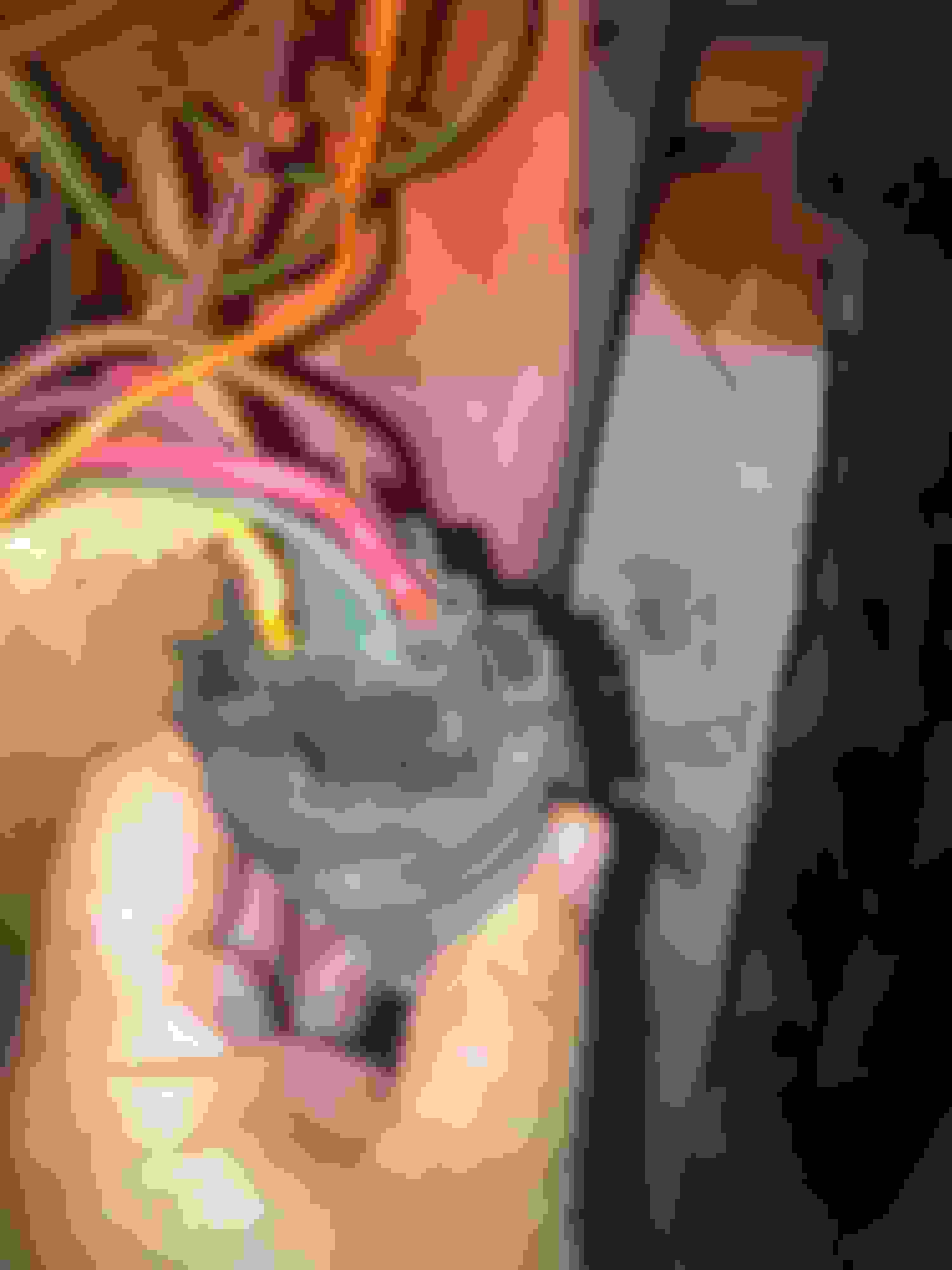
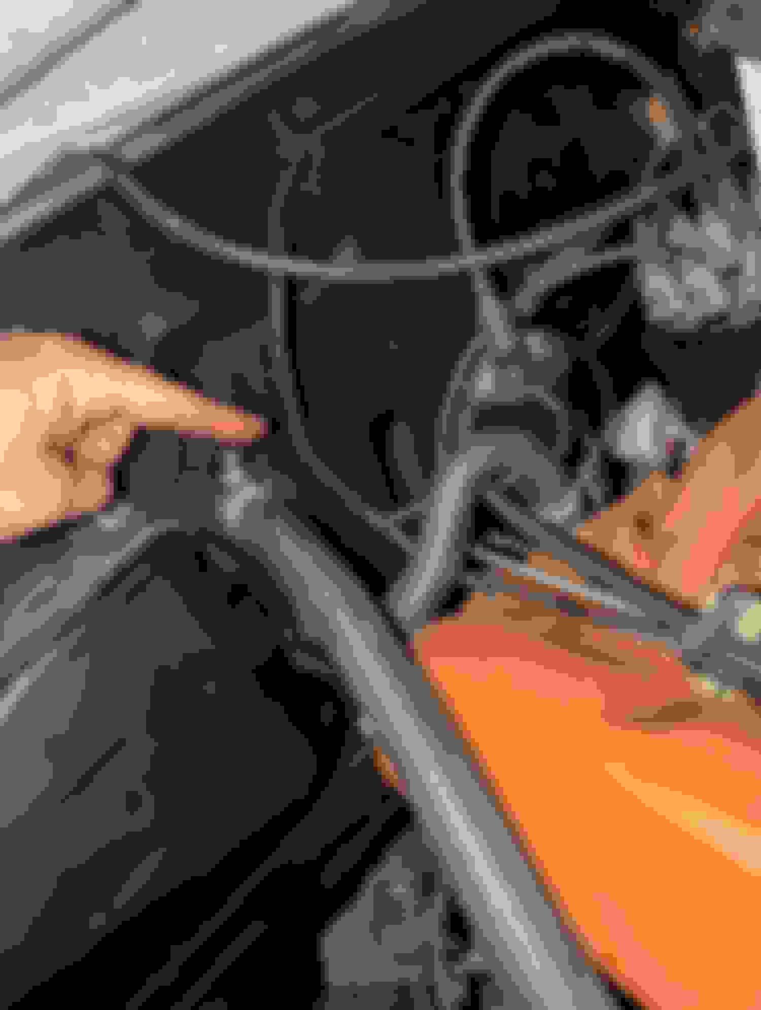
Some great news - the oil pressure sensor/light is somewhat solved! I listened to Loaded and disconnected the Bulkhead connector and the light did go out. That was good news because I knew the issue was with the wiring was under the hood. Although I moved around the wiring several times before somewhat gently, this time I felt is again and noticed this section where I am pointing a litte warm so I grabbed it this time harder - this time I noticed the Oil Light went out with the oil sensor disconnected. So I went to start the car, the Oil light went on and when out as it should! Thanks Loaded, Rocket, and all! I have an Oil Warning Light now!! As you can see it looks like the previous owner black taped the wiring bundle to the igntion coil. The question now is, do I ride as is and see how long it lasts or do I need to remove the electrical tape and see where the issue is? And is the wiring supposed to be a little warm (I don't think so).
As far as the Temp light, the Temp light does not come on while cranking, but comes on when grounded. My temp sensor is the flat top type (which from understanding is incorrect, I need the one with a single prong for a warning light). I ordered that and it will come later this week. Some have said that the you have to have the correct type of temp sensor for the temp warning light go on during cranking. I am not sure if that is true though based on the wiring diagram.
Not all the time but sometime when I start the car, the temp light goes on after it starts and then goes off after a couple of seconds - not sure if this is due to the incorrect temp sensor. I does not do that everytime
The paths I traced are showing the ground connection (-) to the bulb only (green wire). The other side of the bulb is powered (+) by the green/ white wire. The NSS is still never part of the temp bulb circuit, but the back-up lights and temp bulb do both get power from the same fuse on the fuse box which is why the green/ white wire goes to the NSS as well. Here are two new drawings showing where ground is coming from (black) and where power is coming from (red) during both cranking and overheating.
Circuit when cranking:
Circuit when overheating:
You say you grounded your ignition switch and the bulb lit? How did you do this? By touching a wire to the face of the switch while cranking as I suggested? (This would confirm that the ignition switch housing is not getting a good ground) Or did you ground the switch some other way/ not while cranking? At this point, I have described this about as clear as I can so, beyond this I am not sure what else to say if you still do not understand.
Thank you Loaded for the updated wiring drawings with the red and black lines! For clarification on the NSS, is the green/wire electrical flow is into the NSS and the light green coming out of the NSS?
As far as testing the ignition switch ground, I ran a test light to the igntion switch (inside the key hole, around the face of the switch, and also on the outer ring) with the car OFF and with the car CRANKING and all times the test light illumated ON. Did I do that correctly please?
Tried something interesting maybe there is truth to needing to have the correct temp sensor type to have the warning light function properly while cranking in addition to the when engine in running. I believe I currently have a temp sensor for gauges and not a warning light.
I experimented and with pigtails, I connected the green coolant temperature wire to the oil temperature sensor - after I did this, the HOT light acted just like the OIL light (meaning the HOT light turned on when I turned the key to ON, stayed on during engine CRANK and then turned OFF after 2 seconds).
I know this is not exactly how the temp light is supposed to function but perhaps if I had the a temp sensor for a warning light, the temp light will act like it should (coming in the mail on Thursday). Or maybe this means nothing, but I can see how the resistance of the temp sensor needs to be a certain value for the temp light to function during engine cranking. Pulling at straws.
So I got an NOS coolant temp sensor that was 28 years old. When I installed it, the HOT light does not illuminate when cranking. I ordered a two prong coolant temp sensor from Amazon to see if that one works differently - coming tomorrow.
Also, as a reminder, if I connect the coolant wiring to the oil sensor for kicks and giggles, the the HOT light and the OIL light work in tandem.
I wonder know if the starting HOT light circuit is not wired properly or has a short?
Well for kicks and giggles, I orders a double prong temp sensor and it came today. When I installed it to the cold prong, the HOT light works as expected. When I installed it to the hot prong, the light does not illuminate when starting. Although this is not great, my hunch is the HOT light will light when overheating, I just cannot know that the bulb will light each time I started to car. So I guess I just need to randomly check the bulb.
Dumb question, but is there any danger to driving the car with one of the coolant sensor prongs exposed if that is what I wanted to do?
Thanks - I have an idea. Now that I have the double prong coolant sensor and when I hook up a plug to the Cold prong, the HOT light lights up when I turn the key and goes off when the engine is warm (just like it should). As of now when I hookup the coolant temp sensor wire to the coolant sensor HOT prong I cannot get it to illuminate at start up.
However, I jumped the coolant wire to the cold plug and for kicks and giggles, when I start the car, the HOT illuminates when cold. The engine will warm, the HOT light goes off. If the car over heated the HOT light will hopefully go back on because it the coolant wire is also connected to the HOT prong. I love it - now I have a COLD and HOT light wrapped into one. The only thing that is weird is the HOT light will temporarily illuminate when cold but I will know the reason. But This way I have a way to check the bulb works at start up and when the engine the warm. I also liked the Cold light idea. My 68 has it and like it because it alerts me when to take off.
What do you think?
Last edited by matchek; October 21st, 2023 at 07:24 AM.
Well for kicks and giggles, I orders a double prong temp sensor and it came today. When I installed it to the cold prong, the HOT light works as expected. When I installed it to the hot prong, the light does not illuminate when starting. Although this is not great, my hunch is the HOT light will light when overheating, I just cannot know that the bulb will light each time I started to car. So I guess I just need to randomly check the bulb.
Dumb question, but is there any danger to driving the car with one of the coolant sensor prongs exposed if that is what I wanted to do?
You are not understanding how the system works. The two prong senders have a normally closed switch (COLD) that opens when the coolant reaches operating temp and a normally open switch (HOT) that closes when the coolant reaches about 250F. Connecting your temp sensor wire to the COLD terminal with the engine cold is the same as grounding it to the block. Of course the light will come on.
The OIL and GEN light circuits work in a way that with the engine off, the lights will come on, so simply starting the engine is a "lamp test" function. The HOT light circuit does not work that way since the sender only closes to illuminate the lamp when the engine is too hot. As a result, Olds included a separate lamp test wire in the ignition switch that provides a separate ground to the HOT light when the key is in the start position. This is completely separate from the wire to the sender on the engine. If that lamp test function is not working, it means that either the lamp is burned out or the ignition switch or associated wire is bad. Stop wasting time and money with senders. This is not your problem. Study the wiring diagram. As car wiring goes, this is a pretty simple circuit.
Hi Joe, thank for your input in overview. I totally agree with everything you said how the cranking circuit works. I think I understand how the gist of how the coolant temp circuits works as explained in prior posts/wiring diagrams from last week, but I can understand why you think I don't understand how it works based on the the most recent posts of where I proposed an idea that would not be perfect, and outside the box, but may be okay for my use.
As a recap, to get my system to work exactly how it is supposed to be from the Olds factory, it needs to work like Joe and Loaded communicated - and it is also in the Owners Manual that I posted earlier. But like mentioned in earlier posts, for some reason, I cannot get the HOT light to illuminate when I start the car when the temp sender wire is connected to a single prong temp sensor (at least the NOS I bought off ebay) or the hot prong of a double prong sensor. I know it supposed to illuminate when cranking but at least of now, I cannot figure out why the cranking circuit does not work. I get good ground at the ignition switch. Two green wires are connected to the ignition switch. I believe this is wired to the cluster in the dash and it's hard to get to. I don't see how to further diagnose the cranking light function without removing more dash components (which I would try to do if had to). I tried to get underneathe the dash and it looks like I would have to remove the dash to really diagnose further - I welcome input though.
Although the connecting to the cold prong is supposed to light the hot light, and it does when cranking, I just mentioned that is works for clarity to communicate the Cold prong works from the sensor purchased from Amazon as it should. I can return the extra sensors that don't work or meets my need so that's not a problem. I ordered more than what I needed because there is a several day lead time if something doesn't work.
Although it is kind of sloppy as not original (and I generally don't like to do non-original things) in the interim, since I cannot ge the cranking circuit to work right, I proposed the idea of double wiring both coolant sensor prongs to the coolant sensor wire. This way the HOT light would illuminate when cranking the car until the engine was warm, then goes out, then would illuminate again if ever overheating. This is not ideal but would allow me to check the bulb works each time I start the car and also illuminate when overheating. I think the potentially sounds like a great idea. Do you like it?
Last edited by matchek; October 21st, 2023 at 08:54 AM.

 October 15th, 2023 | 11:12 AM