Steering column question 1972 cutlass
#1
Steering column question 1972 cutlass
hi! So I want to replace my turn signal collar since it is broken. I tried gluing it but the glue didn't hold so it is very wobbly. I have a turn signal collar with the attached harness and end block from a low mileage car that I was thinking of using. My question is regarding removal of the old and installation of the new. What is involved with this? There doesn't appear to be much room in the column for the end block and harness to be pulled through the column. Is this a job that requires me to completely take apart the column or is it a simple slip out slip in job? Thanks!
Chris
Chris
#2
It has been a while since I have done that but I believe you have to take off one of the brackets lower down on the column but the harness actually slips in and out of the column pretty easily from the top.
#3
What Scott said. The trick is that you have to disconnect the lower end of the harness then bend the harness just past the connector so the long dimension of the connector is parallel to and in line with the ribbon harness. Tie a string to the connector then pull it up through the column. Use the string to pull the new one back down.
#5
#7
Just an Olds Guy
Join Date: Jul 2008
Location: Edmonton, AB. And "I am Can 'eh' jun - eh"
Posts: 24,525
Chris, here's a DIY on the topic. Guy is working on a Camaro but the principles are the same. Some of it is funny but some of it will give you a great idea about how to get the cancelling cam replaced. You may or may not have all the tools you need but I'm sure Autozone will be able to help you out.
#9
Just an Olds Guy
Join Date: Jul 2008
Location: Edmonton, AB. And "I am Can 'eh' jun - eh"
Posts: 24,525
Hey Chris,
How did everything work out? Did you get the old cancel cam out and new one installed without much problem? I love jobs that should take 30 minutes and end up taking an hour...
How did everything work out? Did you get the old cancel cam out and new one installed without much problem? I love jobs that should take 30 minutes and end up taking an hour...

#10
Hi Allan! Thank you for asking. I wound up running all over creation after work looking for krylon dull aluminum paint for the grills so by the time I got home it was too late to work on it. I'll report back by this weekend. Thanks again everyone!
Chris
Chris
#11

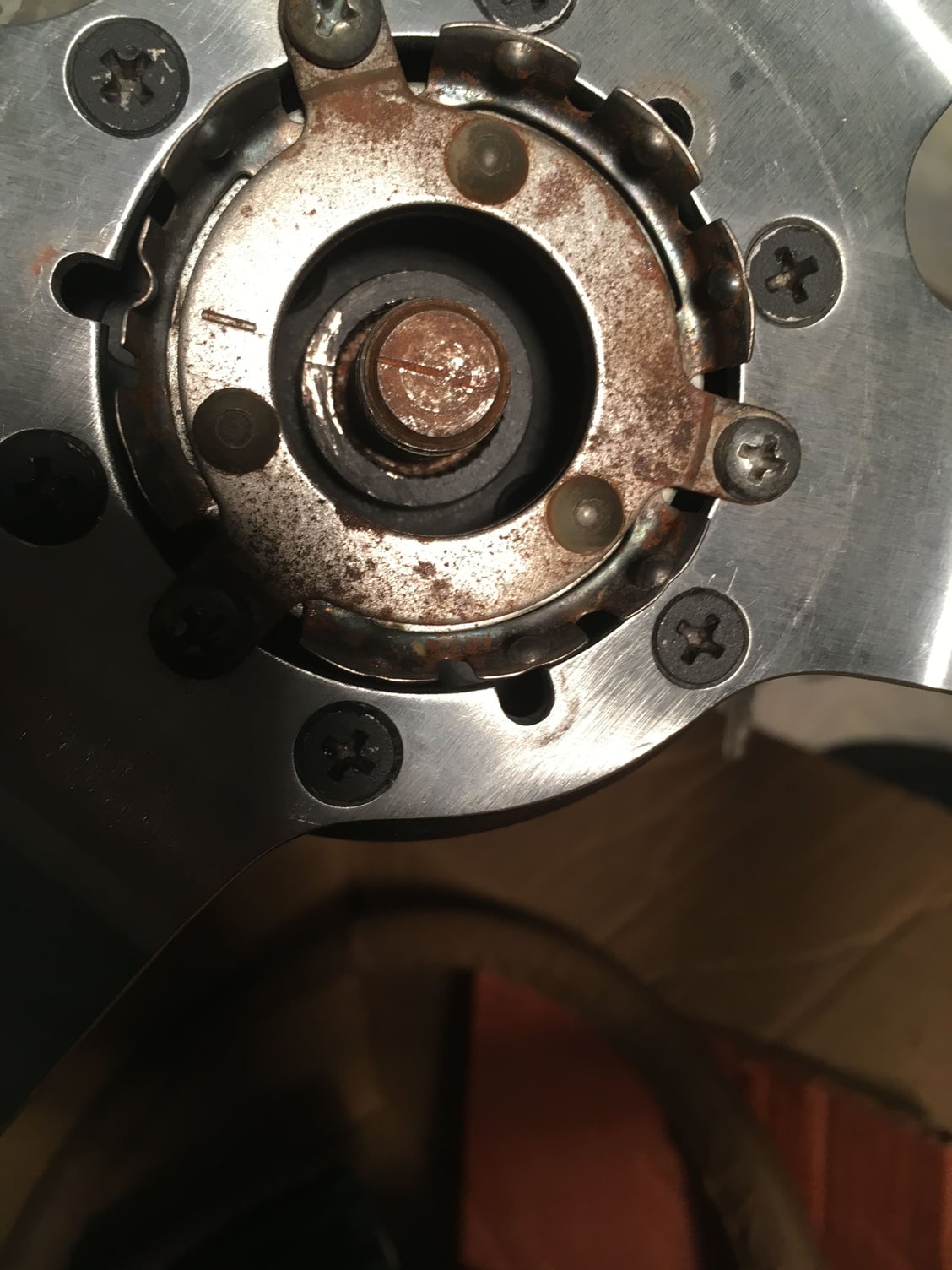
Ok, so the video and all your instructions were great and the old unit came out easily and the near NOS unit fits perfectly. However I still have a few questions as to putting the plates shown in the attached image back on properly. The assembly manual is a little hard for me to understand on this one, regarding the installation of the first plate onto the second plate. Do the little screws attach the solid looking plate to the plate that looks like a flower with the cut out edges? Do I need the lock plate remover tool to get the petal plate back on as shown in the video or can I use a rubber mallet or a piece of wood and a small hammer? And how and where exactly does the ring attach? I couldn't quite see it in the video and I'm not seeing it in the assembly manual. Thank you!
chris
#12
The "flower" plate is the actual lock plate. When you turn the key to the LOCK position, a metal pin is pushed up and engages in whichever of those notches is in the correct orientation. That's how the steering column locks. That pin is actually spring loaded, so if the wheel happens to be turned such that there isn't a notch in the right place, the pin is just pushed up against the backside of the lock plate. As soon as you try to turn the wheel, the pin springs into the first notch that moves into position.
The wire snap ring holds this lock plate down against the pressure of the large spring that is concentric with the steering shaft. You need to use the lock plate compressor tool to push the lock plate down far enough against the heavy spring to either remove or reinstall that snap ring.
Once you get the lock plate in place, that thinner dust cover fits over it and is retained with the three small screws. That tab sticking down from the backside of the dust cover fits into the cutout in the lock plate where the cancel cam post comes up. The dust cover only goes on one way.
#13
Thanks for the detailed answer Joe! So the lock plate installs between the large cooecentric spring and the snap ring? And regarding the direction of the lock plate, does it look like i have it with the correct side out? If my snap ring doesn't completely meet itself as a circle would (got a little stretched when I took it off) does it need to be replaced?
Thanks!
chris
Thanks!
chris
#14
Thanks for the detailed answer Joe! So the lock plate installs between the large cooecentric spring and the snap ring? And regarding the direction of the lock plate, does it look like i have it with the correct side out? If my snap ring doesn't completely meet itself as a circle would (got a little stretched when I took it off) does it need to be replaced?
Thanks!
chris
Thanks!
chris
#16
So am I correct to assume that since I completely replaced the suspension with all new parts that once the car is aligned I'll have to take the steering wheel off and adjust it to the newly aligned front wheels?
#17
Nope. In fact, if you DO need to reposition the steering wheel, you've done something wrong. The entire steering column from box to wheel hub is keyed to only go together in one clocking orientation. The control valve inside the steering box has a specific center point in it's travel. If the steering wheel is not centered when the front wheels are straight ahead, your alignment was done incorrectly. The tie rods are supposed to be adjusted to keep the steering box (and thus the steering wheel) centered in the straight-ahead position.
#19

I have the marks on the hub, threaded rod, and contact assembly all slighted but they're off to the left as the photos show. Should they all be facing up? My wheels are facing straight ahead, or as straight as they could be before being aligned.
#20
Disregard. I moved the steering wheel and hub till the marks were all on top and reattached the steering wheel. The wheels are a little to the right now but I'm assuming that's because they're not aligned yet.
#22
#23
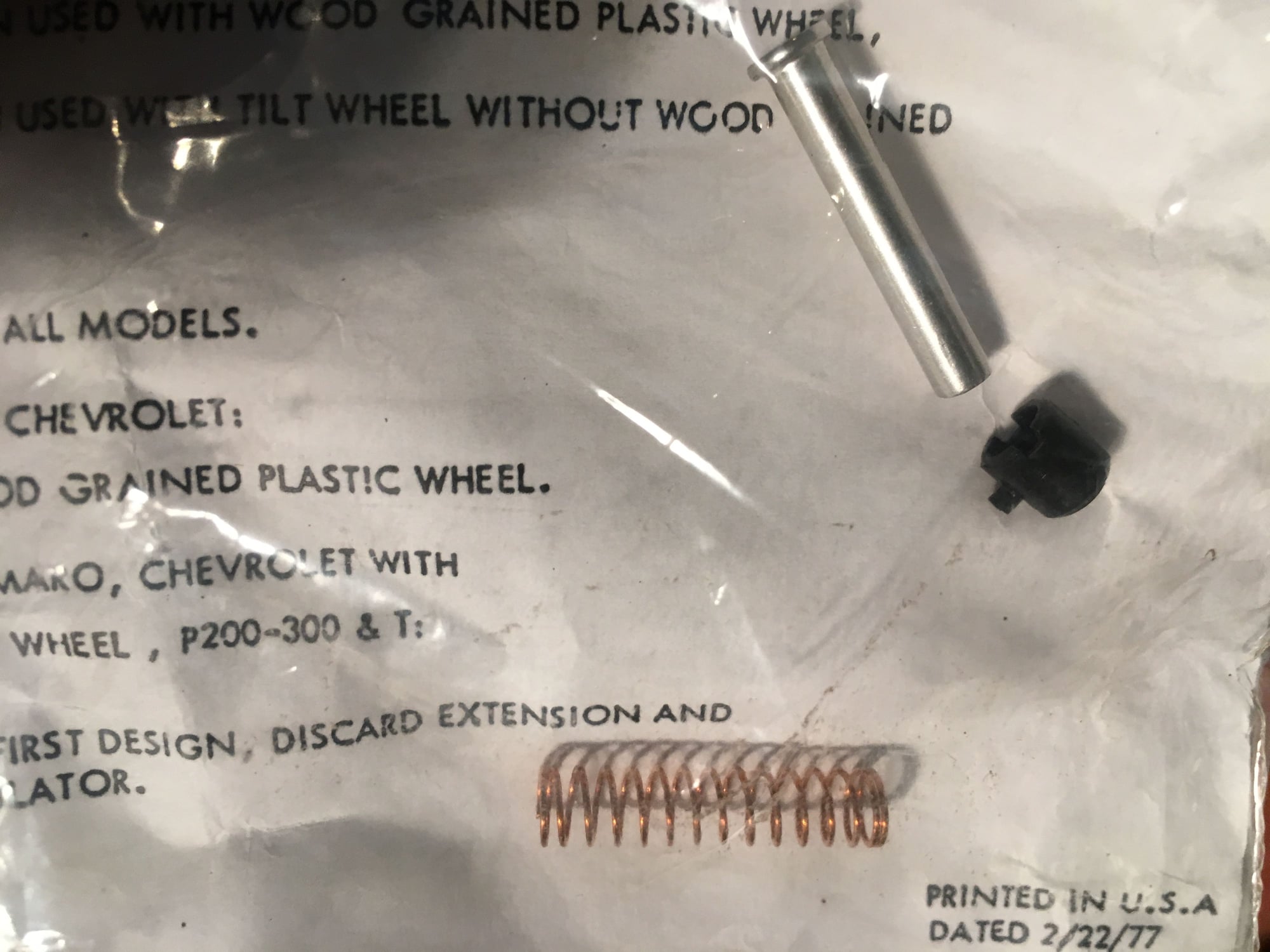
Ok thanks Joe. It seems really tight in there and hard to compress everything. The package states that for "69 and up chevys" the spring should be cut to 3/4" but I'm not sure about if I need to cut it for the Oldsmobile sport wheel. The assembly manual gives a part number but not a dimension. Any thoughts?
Thanks!
chris
Thanks!
chris
#24
Ok thanks Joe. It seems really tight in there and hard to compress everything. The package states that for "69 and up chevys" the spring should be cut to 3/4" but I'm not sure about if I need to cut it for the Oldsmobile sport wheel. The assembly manual gives a part number but not a dimension. Any thoughts?
Thanks!
chris
Thanks!
chris
#25
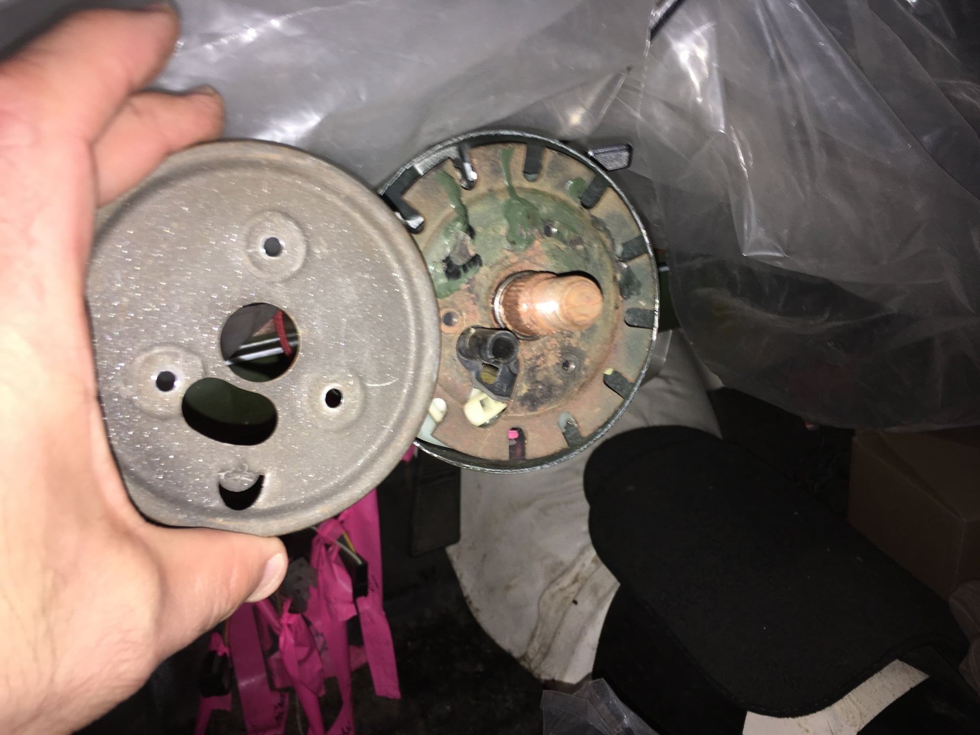
So my horn contact and the plastic retainer keep popping out every time I turn the wheel. Now granted I haven't tightened the wheel down yet but I'm afraid to since I've had to take the locking plate off three times already. Any ideas how to prevent this? I thought about wrapping a layer of scotch tape around the platoc retainer to keep the little nub tab from unlocking but I don't know if that would interfere with the hub where it slips over the contact snout.
Thank you in advance.
Chris
Thank you in advance.
Chris
#26
Or am I possibly in need of a different cam tower assembly? Is it the same for the sport steering wheel and the deluxe supreme wheel? The plastic retainer just keeps popping out of the cam tower. It won't lock properly. Thanks!
chris
chris
#27
The "cam tower assembly" is part of the cancel cam, and there is only one cancel cam for all steering wheels (well, one for regular column and one for tilt column, but the tube for the horn contact is the same). Either your cancel cam is damaged or (more likely) the repro Chinesium retainer isn't quite made right. I'd use a piece of strip caulk or a dab of RTV to hold the retainer in place and be done with it. I assume you are turning the retainer so the little nib locks into the groove in the contact tube.
Thread
Thread Starter
Forum
Replies
Last Post
76CutlassSalon
General Questions
8
July 4th, 2016 08:17 PM
ELECMAN
General Discussion
13
January 22nd, 2012 01:49 PM


