When you click on links to various merchants on this site and make a purchase, this can result in this site earning a commission. Affiliate programs and affiliations include, but are not limited to, the eBay Partner Network.
So I was trying to get my steering wheel centered as well as correct a blinker cancel issue and I see that one tie rod is all the way tightened and the other pretty far out. I assume I would have to disconnect the end and basically adjust them both about the same. I'm having an alignment done next week and just want to make sure everything is correct when done, The wheel centered and the blinker cancel working correctly. Should I just leave it all up the the guy doing the alignment or get the rods centered. The guy doing the work races cars and only works on classics etc. I believe my alignment now is close if not correct, can I secure the wheels in place and disassemble the rods and center them?
thanks,
Steve
The rods should be centered more evenly as Eric identified. Determine if you have the same tie-rods located on both sides (wheels) of the car (at least in terms of length) and/or whether the ferrules are different between both sides of the car. Something appears amiss. I wouldn't think you'd get close to a decent alignment in that configuration employing same tie-rods on both sides & I'd use the same tie-rods & ferules on both sides. IDK
EDIT: Thought of what I stated. Both the LH tie-rods and the RH tie-rods may not in fact be of the same lengths on both sides. Ensure they're the correct tie-rods & ferules for the correct application.
Last edited by Vintage Chief; October 5th, 2021 at 03:21 PM.
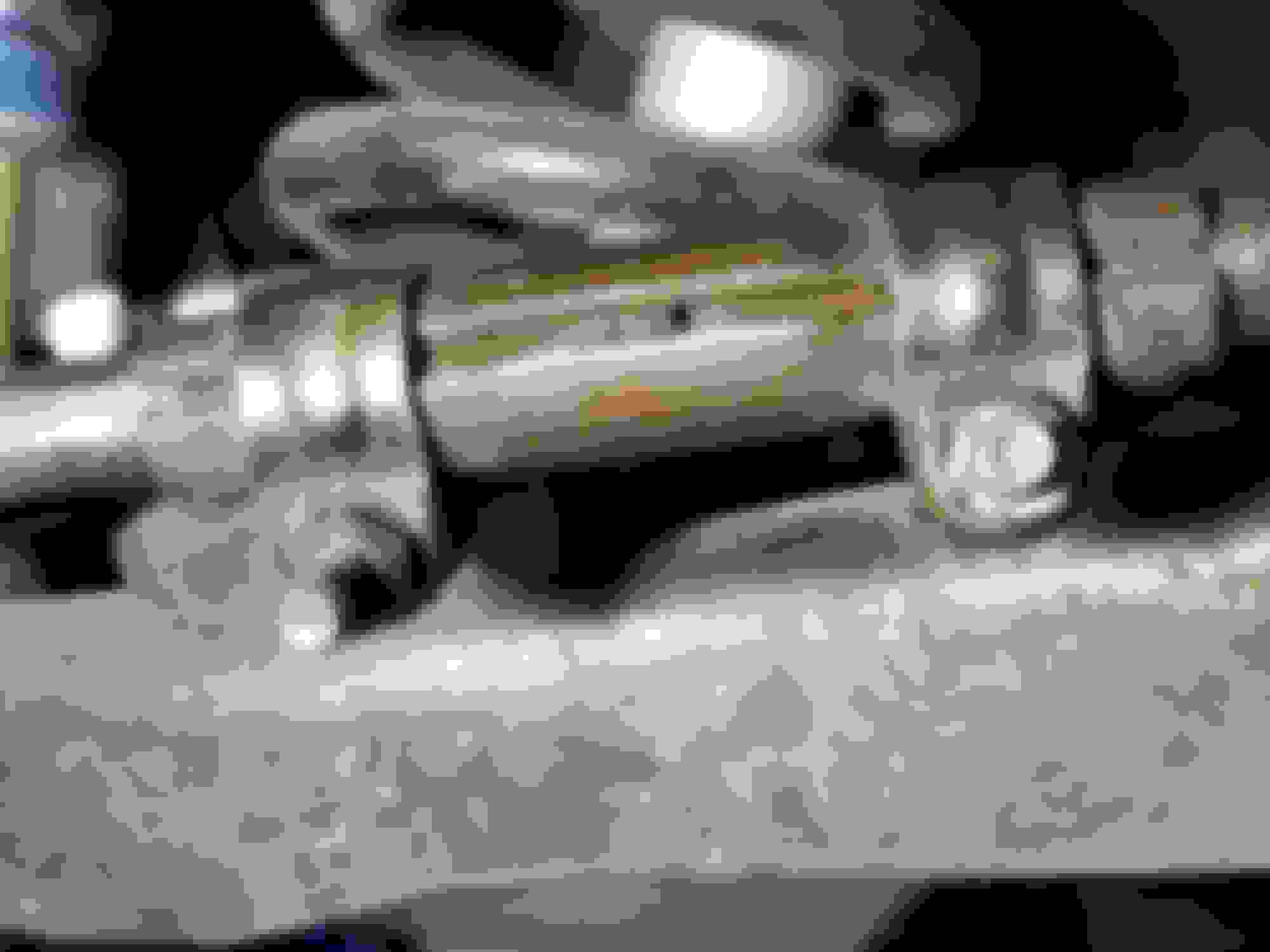
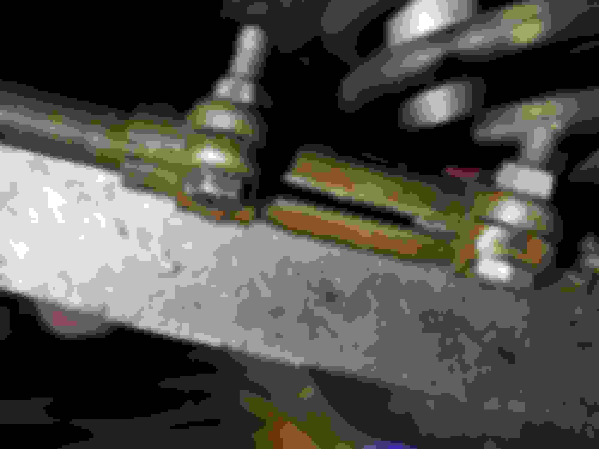
Steve - I'd change out at least this one adjusting sleeve bolt (image) & nut during your work on the tie rod ends (alignment). The threads are pretty worn and there are no threads in one area of the bolt. It probably doesn't matter how the bolt became damaged (it may be a replacement bolt from some other application), but that bolt is shot. Depending on how much work you're getting involved with on the tie-rod ends and adjusting sleeves, you might consider removing the adjusting sleeves and clean (review) the internal threads - at least R&R this one bolt & nut.
I agree, I only notices that when I posted the pics and got a close up view. Should I disconnect the tie rods and adjust the sleeves so the are more balanced then reconnect?
Steve
What it looks like is the steering wheel is off and the tie rods were adjusted to make the wheels straight.
Hope this guy did it for free or for a couple of beers.
I'll bet my paycheck that is EXACTLY what has happened. Assuming the steering wheel is on the splines correctly and correct tie-rod lengths were used on both sides. My guess is that the guy pulled it on the rack, didn't bother placing the wheel in the correct position after setting/checking the caster/camber settings, and did the lazy thing and never looked at the steering wheel again. They either knew they were cutting corners, or their ineptness made them forget to check.
Just because he works only on classic cars doesn't mean he's any good at it. This example seems to prove that.
Note: Avoid that guy again for further alignments.
I believe this is all the OP's doing and he has not brought to an alignment shop yet.
I believe this is all the OP's doing and he has not brought to an alignment shop yet.
Yeesh, I read it wrong. I thought he just got the alignment done by the guy that's going to do the work. Changes the whole conversation then. That's what happens when you don't have enough coffee in you. Need to find out who did the current alignment and keep them from working on that car again, though. Somebody fugged that up. One of the sleeve's clamps are installed wrong as well. GM doesn't recommend placing the sleeve slot in the clamp gap.
If the guy going to work on it is worth his salt, he'll fix everything needing fixed as far as steering alignment and tie rod end adjustments. Just tell him your findings and your end goal and he should be able to take care of it.
Correct, it will be going in for an alignment next week. I have been trying to center the steering wheel for a while. I'd get it centered and then one blinker would not cancel. Having posted questions in the past Joe P stated that GM tried to make this stuff fool proof and put a mark on the column for top center. From there mount your wheel, if tie rods need to be adjusted do it. My column has just a small mark at a slight angle which has had me wondering if it is correct, different than the one Joe posted. So believing that was ok I went to adjust the tie rods to get the wheels straight, which would up with them way out to the limits as in the pic. So I will just show it all to the mechanic, pick up some new nuts and bolts and leave it to him to sort it out. Joe P's Pic showing alignment markings My barely visible marks
This is my position when the wheels are straight, so tie rod adjustment would theoretically get the steering wheel in the correct position. On another post I have going regarding the steering column sheer pins it seems possibly the car was in an accident at some point. No physical signs of prior damage, all looks original.
Steve
this is a prior link with many comments from Joe and others, very helpful to anyone with a similar issue. https://classicoldsmobile.com/forums...utlass-155935/
Last edited by Phoenix8990; October 6th, 2021 at 08:42 AM.
Reason: clarification
Right. The top image is not of an Oldsmobile, but your point is taken. Important to note is establishing the center of the steering gear box first. Clocking it full left, full right then back to center position (with the scribe marks aligned correctly). That centers the turn signal cam correctly and the steering wheel. I'm fortunate (thus far as I know) my steering shaft/column, steering wheel & tie-rod ends are all operating in unison. I think my car (71 CS) was banged on the RH passenger side in some previous life but the frame is straight - I can tell the RH passenger side shows some "history" shall I say. I rebuilt the entire front end steering linkages/assemblies last year and a full body suspension R&R, as well. My PS gear box is weak I believe - I think the internal worm gear has no more life remaining. I've made several attempts to make adjustments - it still demonstrates unacceptable play and a quick loose snap of the wheel when negotiating the smallest of uneven pavements, etc. At any rate, the PS gear box is getting replaced as this winter's project. I feel your pain regarding the steering wheel alignment, signal canceling cam, & tie-rods trepidation. I've installed new steering wheels and a couple steering shafts on previously owned cars years ago - you'll get it done but it's an annoyance working on that stuff.
I checked that the steering gear is centered, that was good news. I was just riding down the highway and I realized the steering shaft is 180 degrees off. I'll disconnect the rag joint, pull it out, and spin the steering wheel 180 and just maybe that will resolve the blinker issue. Makes sense to me. Now I just have to locate the repair kit or a new steering column. I didn't see any shown in Fusick, Speedway, or OPGI, but Summit has an endless list of steering shafts. It's hard to determine which would be a good replacement. I also wonder if having the shear pins is really necessary? I've been driving without them for three years. I assume the point is for the shaft to telescope in the case of a serious accident so the steering wheel doesn't get pushed into the driver? If anyone knows where to get a rebuild kit that would be great. VChief, thanks for your comments.
Steve
I see Jegs has some telescoping shafts and then you use a set screw to secure the length. Seems like I could possibly do that with what I have? https://www.jegs.com/i/JEGS/555/607103/10002/-1
The steering wheel @ 180� is your issue with regards to signal canceling for certain. Spline alignment may be another regarding steering shaft (gear box) tie-rod ends. As Joe pointed out in the other thread on steering, the point is as you stated - during a crash the steering shaft with injected plastic is designed to break and telescope to prevent further (more serious) injury (steering shaft gets impaled into your face, crotch or chest). Many people employ aftermarket solutions which are rigid fits which will not (never) telescope. I believe the primary point is the manufacturer has provided due diligence in designing an OEM factory installed safe steering shaft assembly. What happens after the fact is the owner's decision.
I checked that the steering gear is centered, that was good news. I was just riding down the highway and I realized the steering shaft is 180 degrees off. I'll disconnect the rag joint, pull it out, and spin the steering wheel 180 and just maybe that will resolve the blinker issue. Makes sense to me. Now I just have to locate the repair kit or a new steering column. I didn't see any shown in Fusick, Speedway, or OPGI, but Summit has an endless list of steering shafts. It's hard to determine which would be a good replacement. I also wonder if having the shear pins is really necessary? I've been driving without them for three years. I assume the point is for the shaft to telescope in the case of a serious accident so the steering wheel doesn't get pushed into the driver? If anyone knows where to get a rebuild kit that would be great. VChief, thanks for your comments.
Steve
in one thead you said said you have a ~1/2" of play that i think you determined to be the column assembly.....mine doesnt have that play, w new fr end components there is really little/no discernable play in the steering.
Im not familiar w sheer pin in the column but my guess is besides being able to shear it holds the parts together. The OE joints had an injected plastic in them same thing easy to assemble and held the parts together.
I would guess you could source some good used parts ? Take it apart and see how it was assembled, reassemble w plastic or brass fasteners ?
Maybe adapt some modern parts ?
Im just spilt balling
I had to replace part of the column on a modern vehicle, the OE parts were ~$300 an aftermarket equivalent less than $100. MAny reviews of the aftermarket part indacted the fit between the slideing parts wasnt great and the result was play in the steering. I opted for the OE part and the steering was nice and tight as one expects !
I believe the piece Retro identified is correct for your application. Labeled Steering Shaft, Collapsible, Ididit, 1969-72 A-Body, 18-1/2"L x 3/4"DD. Fitment Application demonstrates Oldsmobile 1969-72 Steering Shaft - collapsible 18-1/2"L x 3/4" DD. Measure to be certain.
The Chevelle one is it, the OPGI doesn't have the flange to connect to the rag joint. A bit pricy but it seems that is where my play is.
thanks for the link
Steve
The one on the Chevelle site with the flange to connect to the rag joint is it. It's interesting how a little play at the shaft turns into much more up at the wheel. It multiplies from 1" diameter to 15" . The plastic pins eliminate it all together, I assume. I'll see if I can insert new plugs or drill it an tap a screw in place. I'm not really concerned about it collapsing in the event of an accident. Or see if I can locate a good used one, I have been trying to solve this issue for a long time.
thanks for the feedback and info.
As previously stated - they aren't "pins", they are "injected plastic". The two pieces are held rigid (during fabrication), the holes are then "injected" (forged if you will) with plastic. The injected plastic maintains rigidity throughout the column shaft. If the injected plastic becomes broken &/or separates you lose: (1) the rigidity imparted to the column shaft by the injected plastic & (2) the ability of the column shaft to telescope (collapse). If you don't care about the safety feature of telescoping collapse, you can perform whatever method you care to resolve your rigidity issue. If that involves drilling holes and inserting nuts & bolts so-be-it.
You'll note aftermarket column shafts which have no injected plastic, no middle shafts and are complete solid column shafts (of various lengths). Yes, that little bit of play becomes quite accentuated.
You might place an ad in the Parts Wanted forum. Might be a good chance one of the member vendors who regularly sell used and NOS parts can help you out.
Note the holes (x2) in the outer shaft. When the inner shaft slots align with the outer shaft holes, the two are held rigid during fabrication. A machine is employed under pressure injection to force plastic through the holes & into the slots of the inner shaft. The entire "assembly" of plastic is contained as two "injected plastic" pieces - one into each of two holes. Each operates as a single unit to maintain rigidity of the shaft; and, (obviously) a breakaway point for telescoping collapse.
I think the "holes" in the inner shaft are not actually holes, but rather are open cavities that are filled with the plastic material as it is injected through the tiny holes in the outer shaft.
I think the "holes" in the inner shaft are not actually holes, but rather are open cavities that are filled with the plastic material as it is injected through the tiny holes in the outer shaft.
Correct. They are slots (or open cavities) - see Post #25.
Very informative, but for the time being I've drilled out the 2 hole to 5/32 and put a roll pin in and tada, the play is gone. At least the little movement that is there seems normal.
thank you all for your input in what has become another learning experience. I have worked on cars as a hobby all my life, restored some, but this restoration has been quite the learning experience. Every issue I have had has required in depth research and many times required doing the repair more than once. I feel like I am really getting to know my car. On to the next killer winter project, replacing the evaporator and heater coils, not going to be fun! The posts will be coming soon.
it shows the inject plastic. My guess is your plastic is missing creating play. Maybe take yours apart like the pic and see what you can see.
it looks like an easy fix if thats the case
Originally Posted by Phoenix8990
It seems odd the holes on the inner shaft should be going the other direction, I think? Where did that pic come from?
Steve
the chevelle thread !!!
your fix is fine (to me)
if theres any slop in it now i was thinking just slide a thin peice of delrin or other plastic between the shafts and then put your pin thru it...w just the pin its likely to *** out over time.

 October 5th, 2021, 09:38 AM


 I rebuilt the entire front end steering linkages/assemblies last year and a full body suspension R&R, as well. My PS gear box is weak I believe - I think the internal worm gear has no more life remaining. I've made several attempts to make adjustments - it still demonstrates unacceptable play and a quick loose snap of the wheel when negotiating the smallest of uneven pavements, etc. At any rate, the PS gear box is getting replaced as this winter's project. I feel your pain regarding the steering wheel alignment, signal canceling cam, & tie-rods trepidation. I've installed new steering wheels and a couple steering shafts on previously owned cars years ago - you'll get it done but it's an annoyance working on that stuff.
")


