When you click on links to various merchants on this site and make a purchase, this can result in this site earning a commission. Affiliate programs and affiliations include, but are not limited to, the eBay Partner Network.
Hey all I just happened to be in the right place at the right time and managed to scoop up a spare working dash clock for my '72 Supreme. I wanted to bench test it to see if it's been converted to the quartz movement. How would I do that? Run a test lead from the harness to the battery and then ground the case?
Dave - That clock is a nice score. It's one feature I don't have in my 1971 CS convertible and it has what I thought was the optional lighting package. I thought the CS convertible came standard with the clock - I really haven't looked it up. I mean the entire car is stock - electric windows, rear view mirror map light, console lighting, tilt wheel, deluxe steering wheel, etc. Maybe the clock was a separate RPO I have no idea. It doesn't bother me, but I've always been curious why it didn't have a dash clock - maybe someone recognized their limited availability and pulled it out and inserted the "blank"? I don't know. Honestly though, I really don't need a clock, but I also don't need a tachometer with an automagic tranny. What I'd really like is the tachometer + clock insert gauge. But I'm cheap and the one's I've seen are astronomical in price.
Norm, the clock was an option separate from all those others you mentioned. My car had the dummy plate in that opening as well, and it now has a tach (installed in 1981, I think). For me, the tach was mandatory with the Dual Gate shifter since I manually shift whenever I'm getting spunky. The trans shifts at 4800 in Drive, and with the 217/221 cam it pulls hard to 5400 or so.
I like having as much engine monitoring as possible - a tach, along with oil pressure, voltmeter/ammeter, and water temperature. All four vehicles in my stable have a tach. 2 are manual trans, so a tach is pretty much a requirement for those, and I've become accustomed to having one.
I agree, I prefer more monitoring as compared to what was/is offered/available. Coolant temperature, oil pressure, volt meter & tachometer cluster would be nice.
Dave - That clock is a nice score. It's one feature I don't have in my 1971 CS convertible and it has what I thought was the optional lighting package. I thought the CS convertible came standard with the clock - I really haven't looked it up. I mean the entire car is stock - electric windows, rear view mirror map light, console lighting, tilt wheel, deluxe steering wheel, etc. Maybe the clock was a separate RPO I have no idea. It doesn't bother me, but I've always been curious why it didn't have a dash clock - maybe someone recognized their limited availability and pulled it out and inserted the "blank"? I don't know. Honestly though, I really don't need a clock, but I also don't need a tachometer with an automagic tranny. What I'd really like is the tachometer + clock insert gauge. But I'm cheap and the one's I've seen are astronomical in price.
Yup Norm...I just happened to be flipping through FB and caught it within minutes of it being listed. Not a bad haul for 75 bones 😀
Another question though...if it is the factory movement, the contacts wont go bad in storage, right?
Yup Norm...I just happened to be flipping through FB and caught it within minutes of it being listed. Not a bad haul for 75 bones 😀
Another question though...if it is the factory movement, the contacts wont go bad in storage, right?
The contacts most certainly can oxidize in storage resulting in increased resistance. I'd spray the contacts with a good circuit board contact cleaner and use a Q-Tip cotton swap to lightly brush the surfaces of the contacts. That should be all you need. If there's no visible sign of corrosion on the contacts &/or board circuitry you should be good to go. Nice find for $75 bones.
The contacts most certainly can oxidize in storage resulting in increased resistance. I'd spray the contacts with a good circuit board contact cleaner and use a Q-Tip cotton swap to lightly brush the surfaces of the contacts. That should be all you need. If there's no visible sign of corrosion on the contacts &/or board circuitry you should be good to go. Nice find for $75 bones.
If there is visible pitting on the contacts or corrosion, I would recommend filing them with a points file. That will improve things significantly. Believe it or not, back in the day, people used to do that to their ignition points to avoid having to replace them.
Dave - That clock is a nice score. It's one feature I don't have in my 1971 CS convertible and it has what I thought was the optional lighting package. I thought the CS convertible came standard with the clock - I really haven't looked it up. I mean the entire car is stock - electric windows, rear view mirror map light, console lighting, tilt wheel, deluxe steering wheel, etc. Maybe the clock was a separate RPO I have no idea. It doesn't bother me, but I've always been curious why it didn't have a dash clock - maybe someone recognized their limited availability and pulled it out and inserted the "blank"? I don't know. Honestly though, I really don't need a clock, but I also don't need a tachometer with an automagic tranny. What I'd really like is the tachometer + clock insert gauge. But I'm cheap and the one's I've seen are astronomical in price.
They make quartz conversion kits for blocks that do away with the mechanical points. Other than the second hand moving constantly (no more tik tock as the second hand moves) there is no visible change.
I did the quartz conversion on my car probably 30 years ago, it�s still keeping perfect time. I haven�t bought one since, so I don�t know how expensive they are. Something to keep in mind until you get the TicTokTach.
Run a test lead from the battery and ground the case if there is no other ground terminal.
So do I run a test lead from the terminal on the back of the clock to the positive terminal on the battery and then just touch the case to the negative terminal on the battery?
So do I run a test lead from the terminal on the back of the clock to the positive terminal on the battery and then just touch the case to the negative terminal on the battery?
That would work. After all, the negative terminal of the battery is connected to the chassis/frame which is then connected to the dashboard which achieves its ground from the negative (-) terminal of the battery. Assuming the circuit board contained within the dashboard is a known good ground (emanating from the ground of the chassis/frame which was obtained from the negative (-) terminal of the battery) you will have completed the circuit when the clock is assembled into the dashboard. The positive (+) pin of the clock is isolated from the ground of the clock.
So again, you're bench testing the clock itself for functionality (separate from the ground of the dashboard) - you're not testing functionality based upon a ground connection w/in the dashboard. If the dashboard (instrument panel) ground wire is a known good ground, you're golden (if the clock functions correctly w/ your bench test).
So I ran a test lead from the terminal on the clock to the positive terminal on the battery in my daily driver and then touched the clock case to the negative terminal on the battery...also ran a test lead from the case to the negative terminal...no movement of the second hand. Maybe I need to clean the contact points where I'm attaching my test leads?
You're sure you're on the correct positive (+) pin on the clock? I would think there may be two - one for a clock lamp and one for power to the clock itself?
The metal plate with either the 2 or 3 screw holes used to secure the clock to the instrument panel (front side) - is that plate not the “ground” used when the clock is installed? I don’t own one and I’m not looking at a diagram. That metal plate may be the ground which case that’s where you need the the negative terminal. That metal plate may be isolated from the case of the clock. Two things to consider. With a multimeter test for continuity on the positive pin terminal. You should have ~0 ohms resistance. I would remove the four mounting nuts (includes the positive pole nut) remove the case and examine the internal board.
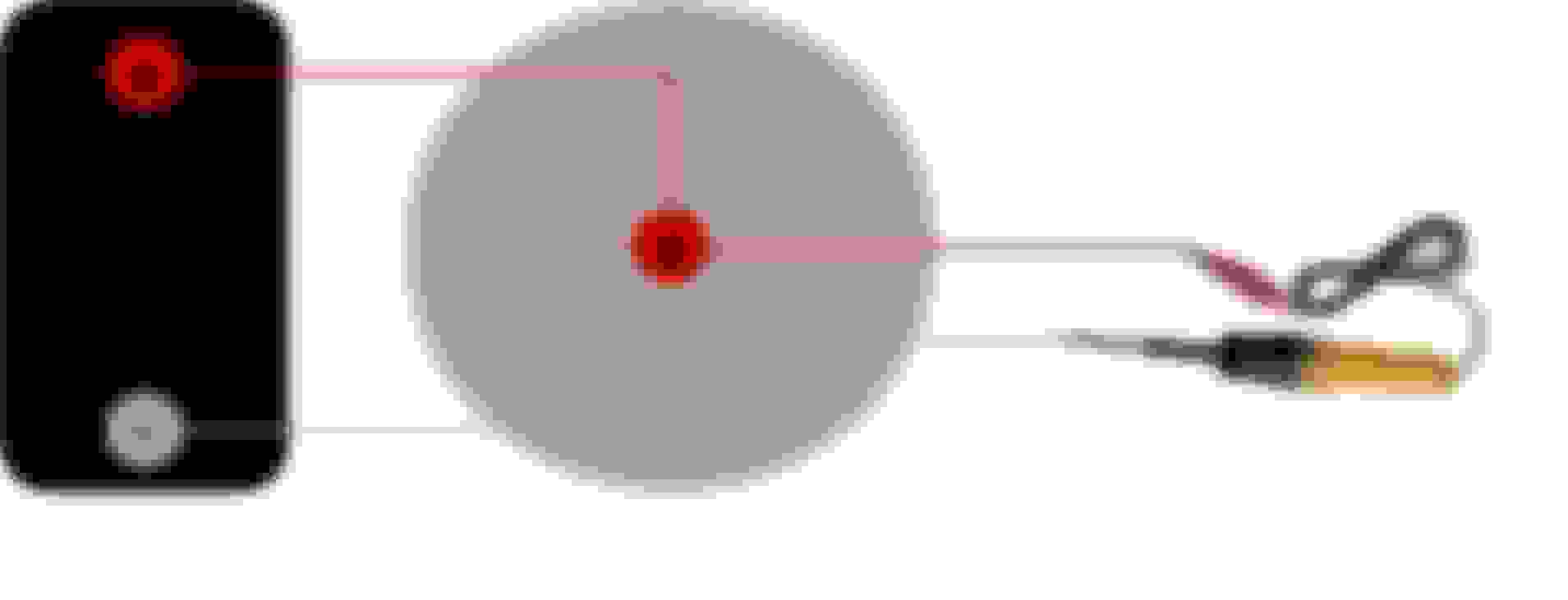
I grabbed an image from another CO member to visualize the back of the clock. I can see as the metal lamp retainers are inserted into the back of the clock they obtain their ground from the case. I think my very next approach would be to remove the positive (+) terminal nut and clean the post the nut is attached to and the positive (+) pin terminal lead clip with a wire brush until you are satisfied you see clean shiny bare metal. Do the same for a point on the case, as well - clean shiny bare metal - then try your bench test again. Outside of this, I'd guess a continuity check is next. Here's a guy who took one completely apart.
Would that consist of using a test light, and if so, how 🤔?
A MM is preferable. It's easiest to test ground potential of the clock via the case (since we now know the case is in fact the ground). Like your car, the (-) negative terminal of the battery supplies the ground potential for your entire car. If I place one probe of the MM into either the ohms (resistance) or continuity socket of the MM and secure that probe onto the (-) negative terminal of the battery, when I then place the other probe of the MM onto any point on the chassis, frame, body etc. I should read ~0.0 ohms - indicated via either a buzzing sound from the MM continuity socket or ~0.0 ohms resistance. This would demonstrate a circuit which has continuity of ground potential e.g. you have continuity at the point where you placed the probe. Same applies bench testing your clock for ground potential.
Insert one MM probe (either black or red) into the MM socket labeled either Ohms (resistance) or continuity (depends on your MM) then secure that probe to the negative (-) terminal of the battery insert the other probe into the MM socket black socket. Next, take the other probe and place it onto the case of the clock - you should demonstrate ~0.0 Ohms (resistance) or the buzzer (continuity) should sound. This should be called out in your MM manual, but here's a video.
At this point, if you don't have continuity of ground potential, then you have a bad clock case ground and you need to clean a surface of the case to clean, shiny bare metal. If you do have a good ground continuity potential, checking continuity of the clock positive (+) will be more cumbersome, but start with ground continuity first. Here's a helpful video - pretty simple to test ground potential.
If you're going to test this with a test light, you'd configure the battery>clock cables and test light cables as demonstrated in the image I created below. If the lamp illuminates you have both (+) and (-) circuit flow; if not, either the (+) or the (-) is faulty. You're testing w/ the test light which would be exactly as you did with the clock, instead you're substituting the test light for the clock to visualize the result. If you perform the ground potential continuity I described previously and you have continuity of the ground potential circuit, you can rule out ground potential and the issue resides w/in the positive (+) circuit.
I have repaired several dozen of this original style mechanical clock movement over the years, and there are only a few reasons they tend to stop.
1: The original oil used to lubricate the movement jells and the movement essentially freezes up. This is the place you need to start because if you cannot get the movement running there is no point in going further. Take the clock apart as shown in the video vintagechief added to post #25. Spray the movement down with brake clean or carb cleaner and wind the movement manually as shown in the video when he is testing the new movement (you may have to carefully move the flywheel to get the movement started). It may take several rounds of spraying the movement down with cleaner and running it before you remove all of the old oil. If you can get the clock working by manually winding it, spray it thoroughly with WD40 or some other thin lubricant.
2: The points get corroded. These clocks wind themselves by activating an electromagnet when the points close. The magnet throws the spring-loaded movement away from touching points, and when the movement winds down to close the points again, the action repeats. To repair corroded points, close them with a points file or small piece of 220 grit sand paper folded so it is sanding both points and clean the points until the corrosion is gone. (I have had a few clocks that had slight corrosion where the point arm meets the electromagnet housing in which case you will need to remove the magnet lever to clean the pivot area where they come together)
3: The electromagnet wire is burned up. This will be obvious when the clock is apart as the wire will be scorched and likely burned apart where the wire attaches to the positive stud. This can happen if the car battery is allowed to drain down to basically no voltage. At that point there is not enough voltage for the magnet to throw the points apart, but there is still enough amperage to burn the thin magnet wire up. Although points will usually need cleaned, Problems 1 and 3 are the most common problems I have seen while repairing these movements. If you have a burnt magnet, the only option is to replace it. You can replace the entire movement as shown in the video, or you can find another used movement that has a good magnet and replace only the lower platform.
4: The clock has been apart before or dropped and the precision parts inside have been bent or damaged. This will require a replacement movement (new or used from another clock).
Cleaned the contact points for my test leads and tried again..still no movement. At this point I'm gonna wait till I get ready to install my tic tock tach and test the clock by installing it as it was meant to be.
If it's the kind with points, it's easy to fix. Slide it out of the case, and take a thin two sided file and open the points and file the contacts. Then bench test it.
Wow, that coarse? I would have thought a much finer grit such as 1000 or 1200 would work better.
Yes, if the points have a poor connection 1000 or 1200 will not really work. 220 - 400 Is what I use. Fold the paper over so it has abrasive material on both sides and put pressure on the points to hold them together while sanding. Points in these generally lose connection due to corrosion and sparking with creates a pitted uneven surface. Although, I always sand the points in these clocks to get back to a smooth surface the main issue is usually gummed up lubricant causing the the movement to stop.
I have repaired several dozen of this original style mechanical clock movement over the years, and there are only a few reasons they tend to stop.
1: The original oil used to lubricate the movement jells and the movement essentially freezes up. This is the place you need to start because if you cannot get the movement running there is no point in going further. Take the clock apart as shown in the video vintagechief added to post #25. Spray the movement down with brake clean or carb cleaner and wind the movement manually as shown in the video when he is testing the new movement (you may have to carefully move the flywheel to get the movement started). It may take several rounds of spraying the movement down with cleaner and running it before you remove all of the old oil. If you can get the clock working by manually winding it, spray it thoroughly with WD40 or some other thin lubricant.
2: The points get corroded. These clocks wind themselves by activating an electromagnet when the points close. The magnet throws the spring-loaded movement away from touching points, and when the movement winds down to close the points again, the action repeats. To repair corroded points, close them with a points file or small piece of 220 grit sand paper folded so it is sanding both points and clean the points until the corrosion is gone. (I have had a few clocks that had slight corrosion where the point arm meets the electromagnet housing in which case you will need to remove the magnet lever to clean the pivot area where they come together)
3: The electromagnet wire is burned up. This will be obvious when the clock is apart as the wire will be scorched and likely burned apart where the wire attaches to the positive stud. This can happen if the car battery is allowed to drain down to basically no voltage. At that point there is not enough voltage for the magnet to throw the points apart, but there is still enough amperage to burn the thin magnet wire up. Although points will usually need cleaned, Problems 1 and 3 are the most common problems I have seen while repairing these movements. If you have a burnt magnet, the only option is to replace it. You can replace the entire movement as shown in the video, or you can find another used movement that has a good magnet and replace only the lower platform.
4: The clock has been apart before or dropped and the precision parts inside have been bent or damaged. This will require a replacement movement (new or used from another clock).
What did you use to keep the studs from turning while you loosened the nuts on the back?
If you watch the video in post #25 it shows a couple of solutions. Start by spraying the nuts with penetrating lubricant. In my post above, I was referring to the movement. Most of the ones I have repaired have been chevelle or tic-toc-tach clocks as they use the same movement (although some early GM cars use a slightly different movement with a different magnet/ point design).
After some consideration(s) regarding a clock spurred on by Dave's clock threads, I've decided to put a clock in my 1971 CS convertible. It's always going to be a hit-or-miss situation regarding the operational functionality of an OEM (used) electric mechanical device such as a clock but this original appears to have been properly serviced (fingers crossed). I thought it best to try to secure an original so that's what I did. I bought the one Loaded68W34 provided a link URL for in another thread:
Appears it doesn't come w/ the lamp pigtail, we'll see when I open the pkg. It's a non-issue - I've found a couple places who sell new lamp wiring pigtails and I might be able to secure one on this site (possibly); worst case scenario I make one.
So, I haven't been in the dash in some time (a non-issue), I'll be curious to see two things: (1) If the OEM (standard) wiring loom (harness) of a 1971 CS convertible contains the positive (+) male spade (and wire) for the clock or I'll have to splice into the wiring loom (harness) and make the positive (+) spade wire; and, (2) whether there exists a positive (+) spade terminal & wire for the lamp pigtail. Both of these are non-issues, I'll find out when I open the dash and examine the wires. The lamp pigtail as noted in the one image from another CO member and the other images are the clock I purchased. I don't NEED this clock, but I think it will be a nice addition to a Cutlass Supreme convertible model.
Will it come with the pigtail or not? I'll find out shortly.
Ok..so I gave up on trying to get it working and bought another one. Works great...now, how can I keep it from giving up the ghost while it's in storage?