
anyone have a wiring diagram for a 71 442?

Registered User
Joined: Feb 2008
Posts: 11,798
From: Plano, TX
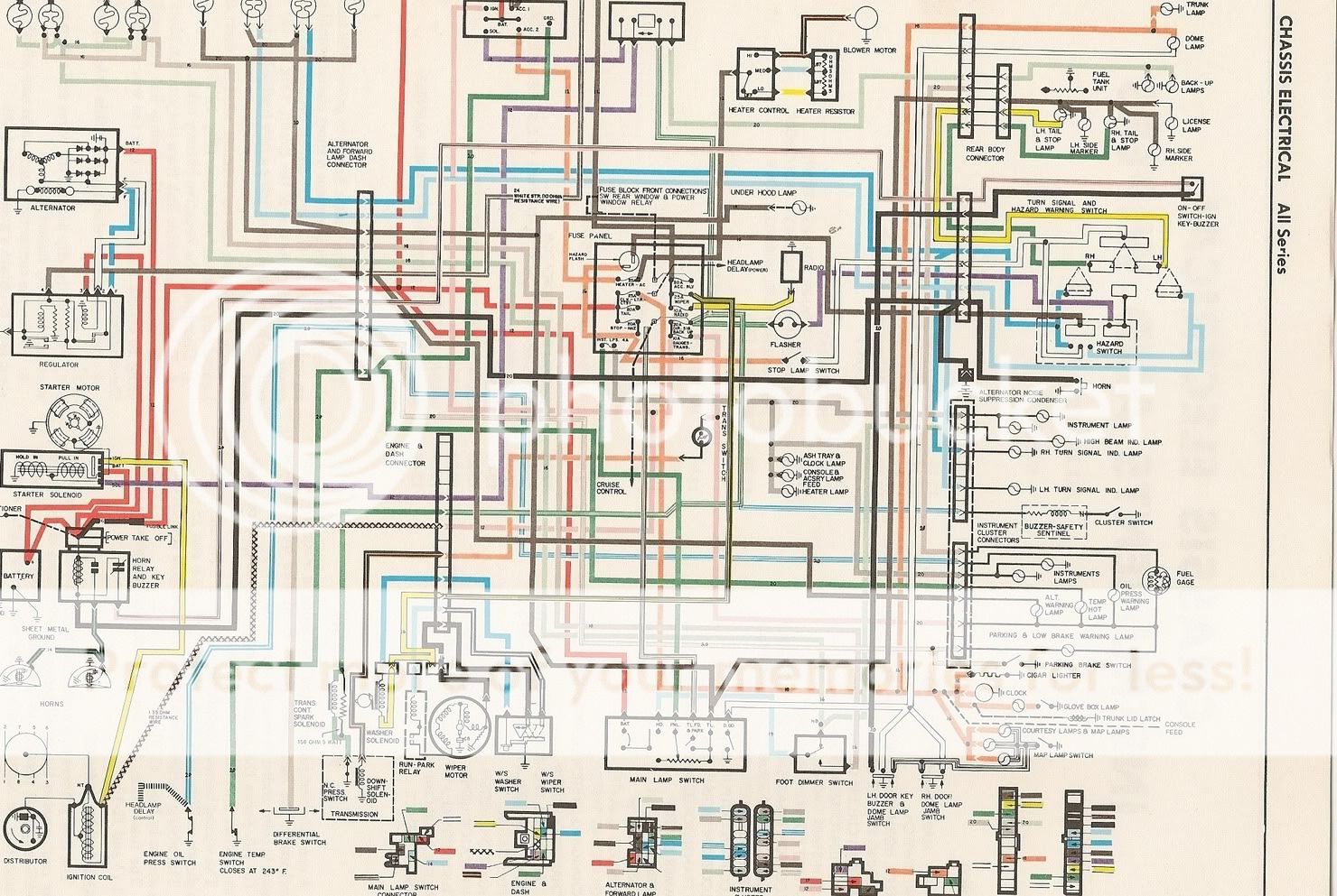
Here is one for a '72. They will be very similar, if not alike.
Hope this helps until you find a service manual...
If you cannot read this one (CO shrunk it down) shoot me an email address and I can send the full sized one.
Hope this helps until you find a service manual...
If you cannot read this one (CO shrunk it down) shoot me an email address and I can send the full sized one.
Last edited by Lady72nRob71; Feb 23, 2009 at 05:08 AM.
Old(s) Fart
Joined: Mar 2007
Posts: 50,803
From: Northern VA
That's a Cutlass diagram, isn't it? The 442 wiring diagram is a black & white one later in the CSM. The big difference is that the 442 would have had an internal regulator alternator for 1971.
Registered User
Joined: Feb 2008
Posts: 11,798
From: Plano, TX
So watch for these differences between the 71 and 72 diagrams.
Thread Starter
Registered User
Joined: Dec 2008
Posts: 1,173
From: Somerset Wisconsin
My fuse box was bad
My fuse box was deteriorated so I ended up with a 72 standard harness and there were several changes from my 71 with guages wiring.The guage plug in plastic pieces were wired different and I had to rewire a few things to still be able to use my outside harness. It took a little time but I got it done. I still need to know where to plug in a few things.
Thanks for the schematic,
Dave
Thanks for the schematic,
Dave
Registered User
Joined: Feb 2008
Posts: 11,798
From: Plano, TX
My fuse box was deteriorated so I ended up with a 72 standard harness and there were several changes from my 71 with guages wiring.The guage plug in plastic pieces were wired different and I had to rewire a few things to still be able to use my outside harness. It took a little time but I got it done. I still need to know where to plug in a few things.
Thanks for the schematic,
Dave
Thanks for the schematic,
Dave
-Rob

Pro GM
Joined: Jan 2010
Posts: 53
From: Columbus, OH
Do you still have a blowup of that wiring diagram and will it work with a 72 Toronado? Thanks.
Registered User
Joined: Feb 2008
Posts: 11,798
From: Plano, TX


Just an Olds Guy
Joined: Jul 2008
Posts: 24,528
From: Edmonton, AB. And "I am Can 'eh' jun - eh"
Your question is basically the same as the one in this link: https://classicoldsmobile.com/forums...-diagrams.html
Here's the diagram posted there:
If you copy it into "my pictures" on your PC you can resize it or print it
Here's the diagram posted there:
If you copy it into "my pictures" on your PC you can resize it or print it

Registered User
Joined: May 2009
Posts: 2,212
From: USA
If worse comes to worst.
There's always an American Autowire kits you can buy and replace it with.
VERY VERY simple to install even for a beginner.
http://www.americanautowire.com/factoryfit.html
There's always an American Autowire kits you can buy and replace it with.
VERY VERY simple to install even for a beginner.
http://www.americanautowire.com/factoryfit.html

Registered User
Joined: Apr 2010
Posts: 1
Thanks Rob for the diagram copy. It was a lot of help. So I thought I would share my solution. Fuel guage quit working. I thought there was a short causing it to read FULL all the time. Instead, the circuit was not finding a ground. It needs a ground to return the guage to the "E". The sending unit seaks ground through the resister built into sending unit. Pulled the unit, chk'd w/meter-OK. Cleaned the contact rail w/ carb cleaner & a wire brush, removed varnish- Now it works fine. Destroyed the fuel "strainer" but still available through OER. 3/8". Part# K405. Pull strainer off of P/U pipe. Bottom of unit & wrap shield come right off. Thanks Again!!!!
Registered User
Joined: Feb 2008
Posts: 11,798
From: Plano, TX

Registered User
Joined: Nov 2010
Posts: 2
I am getting to rewire my 72 cutlass, could you email me a larger pic of the diagram? My email is irdbosn@swbelll.net
Thanks,
Vincenet
Thanks,
Vincenet

Registered User
Joined: Mar 2013
Posts: 51
From: Michigan
72 A Body wiring harness
Hello,
I got a '72 parts car (350 automatic w/ AC) to finish up my 71 Cutlass S project (455 automatic w/ AC) and ended up using the '72 wiring. The '72 harness is definitely different and is very good except for cutting into the engine wiring harness so an HEI distributor could be used.
The '71 I'm trying to finish does not use an HEI, but does have a Pertronix unit installed inside the distributor.
I was wondering if you could help me out with a picture of the engine compartment wiring diagram w/o rally gauges.
I want to repair the cut wire and connect it properly, but need a diagram to determine where it gets connected.
I appreciate any help you could give.
Thank you for your time!
Brad
Olds Fever
Joined: May 2011
Posts: 4,526
From: New York (Upstate)
Hello,
I got a '72 parts car (350 automatic w/ AC) to finish up my 71 Cutlass S project (455 automatic w/ AC) and ended up using the '72 wiring. The '72 harness is definitely different and is very good except for cutting into the engine wiring harness so an HEI distributor could be used.
The '71 I'm trying to finish does not use an HEI, but does have a Pertronix unit installed inside the distributor.
I was wondering if you could help me out with a picture of the engine compartment wiring diagram w/o rally gauges.
I want to repair the cut wire and connect it properly, but need a diagram to determine where it gets connected.
I appreciate any help you could give.
Thank you for your time!
Brad
I got a '72 parts car (350 automatic w/ AC) to finish up my 71 Cutlass S project (455 automatic w/ AC) and ended up using the '72 wiring. The '72 harness is definitely different and is very good except for cutting into the engine wiring harness so an HEI distributor could be used.
The '71 I'm trying to finish does not use an HEI, but does have a Pertronix unit installed inside the distributor.
I was wondering if you could help me out with a picture of the engine compartment wiring diagram w/o rally gauges.
I want to repair the cut wire and connect it properly, but need a diagram to determine where it gets connected.
I appreciate any help you could give.
Thank you for your time!
Brad
Registered User
Joined: Mar 2013
Posts: 51
From: Michigan
Does anyone have 1972 Olds A Body engine wiring harness?
Thanks for the offer CRUZN66, but I was just hoping to get a single picture of the non-rally-pac engine wiring harness so I can put the '72 back to original.
Do you know what wire one would tap into if they were to install an HEI distributor?
Do you know what wire one would tap into if they were to install an HEI distributor?
Registered User
Joined: Mar 2013
Posts: 51
From: Michigan
Need 1972 engine compartment wiring diagram.
Sorry for the confusion.
All I want to do is reconnect the wiring back to the stock location after the black wire (which has ''resistance - do no cut' embedded into the wiring insulation) was rerouted to an HEI distributor.
Anyone know where this bulkhead wire goes originally?
Thanks!!
All I want to do is reconnect the wiring back to the stock location after the black wire (which has ''resistance - do no cut' embedded into the wiring insulation) was rerouted to an HEI distributor.
Anyone know where this bulkhead wire goes originally?
Thanks!!
Registered User
Joined: Mar 2013
Posts: 51
From: Michigan
Resistance wire?
Sorry for not understanding your earlier reply, but, YES, it has the resistance wire ('RESISTANCE DO NOT CUT' on the wire insulation), which is the one that was tapped into.
Knowing that, do you know where I should reconnect?
Thanks!!

Registered User
Joined: Aug 2016
Posts: 152
From: Oklahoma


Registered User
Joined: Jun 2009
Posts: 4,293
From: Palm Bay, FL
Can you download the picture from my photobucket account?
http://i90.photobucket.com/albums/k2...1.jpg~original
http://i90.photobucket.com/albums/k2...1.jpg~original
Registered User
Joined: Aug 2016
Posts: 152
From: Oklahoma
Can you download the picture from my photobucket account?
http://i90.photobucket.com/albums/k2...1.jpg~original
http://i90.photobucket.com/albums/k2...1.jpg~original
Registered User
Joined: Jun 2009
Posts: 4,293
From: Palm Bay, FL
It works but some of the stuff in the top picture is cut off and I need to know what it says because I am having troubles with making my car start from the ignition key. I am getting no power to my fuse but I have it everywhere else in the fuse box. Thought it might be the power coming into the fuse box feeding the fuse for ignition, whether than it being in the mechanical switch. I'm not a pro and I haven't had time to seat down and follow out the wires yet. I am guessing the blue box on top of my steering column is the mechanical switch where I see the red wire going into it and Violet color coming back out to feed the starter?
Registered User
Joined: Aug 2016
Posts: 152
From: Oklahoma

It works but some of the stuff in the top picture is cut off and I need to know what it says because I am having troubles with making my car start from the ignition key. I am getting no power to my fuse but I have it everywhere else in the fuse box. Thought it might be the power coming into the fuse box feeding the fuse for ignition, whether than it being in the mechanical switch. I'm not a pro and I haven't had time to seat down and follow out the wires yet. I am guessing the blue box on top of my steering column is the mechanical switch where I see the red wire going into it and Violet color coming back out to feed the starter?


Last edited by Letsrunum; Aug 23, 2016 at 04:49 PM.
Administrator
Joined: Oct 2009
Posts: 42,496
From: Poteau, Ok
The pink wire off the column connector is for the ignition. Check to see if your bulkhead connectors are tightly secured under the master cylinder. Here is a link to a Chevelle schematic, it should be close.
https://s3.amazonaws.com/ClubExpress...xAGX0Vwapfs%3D
https://s3.amazonaws.com/ClubExpress...xAGX0Vwapfs%3D


Registered User
Joined: Apr 2009
Posts: 14
are you able to send fullsize wiring diagram having starter issues

Thread
Thread Starter
Forum
Replies
Last Post
RALLYE KID
Miscellaneous Classifieds
5
Apr 14, 2022 06:54 PM
RALLYE KID
Parts For Sale
1
Aug 18, 2015 05:48 PM
oldzy
Electrical
4
Sep 10, 2009 05:23 AM


