When you click on links to various merchants on this site and make a purchase, this can result in this site earning a commission. Affiliate programs and affiliations include, but are not limited to, the eBay Partner Network.
I have CRS and have forgotten a lot so I need some help.
Several years ago, I removed the externally regulated alternator along with the voltage regulator. I replaced the alternator with a higher output, internally regulated alternator. I used one of these; https://www.ebay.com/itm/1963-74-GM-...wAAOSwG8tcm8DN
to make the new alternator and the ididot light work just because it was clean and easy with no wire cutting involved.
Now the current problem. The idiot light came on. When I removed the alternator I found the main red wire coming from the alternator was loose, yeah it had to be my fault but I don't know when I messed it up. So I took the alternator to Autozone to get it tested. I have a friend who owns a 70 442 and has been working on Oldsmobiles all his life and also in the autoparts business his entire working career who now works at Autozone but he wasn't there that day and a dud did the test. He says the alternator is good. I suspect it has a problem, maybe just the internal regulator.
Now my question. I hoped I could get an explanation of what the "Kit" I bought does. It plugs right into the regulator wire terminal. There are 4 wires there, I believe from top to bottom they are Blue, White, Red, and Brown. Could someone tell me what the wires are for and what the plug in the "Kit" does. I wondered if the Kit plug was a jumper to "Connect" at least two of the wires or what and how many jobs does said plug do and how many wires does it connect?
I will get the alternator tested again, I feel sure the loose connection caused some problem(s).
Thanks in advance for any information,
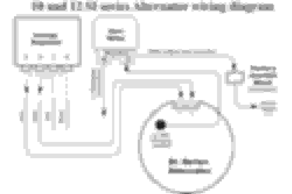
All that wiring kit does is what is shown in this diagram. The connector that replaces the external regulator simply has jumpers inside it. The other short harness just converts the 10DN plug to a 12SI plug.
Well it turns out I had a few minor problems and no major problems.
First, the battery was dead, or nearly so in my trusty old Craftsman multi meter and giving some good and some bad results. That is when I posted this question, I just couldn't figure out what I was doing wrong. Thanks to Joe posting the diagram I figured out the dead battery in the meter, again old age and CRS. So found nothing wrong with the parts, not even the alternator. So I sought some advice from someone even older than I but in the alternator/starter business for a long time, had to drive 45 min to see him. He checked the alternator again, good. We talked and he said maybe a ground. I took care when detailing and painting stuff when I did the 455 swap to have good ground points, engine to frame, engine to body, etc etc, but didn't think a thing about an alternator needing grounded. The alternator guy showed me a bolt hole (5/16 thread) on the back of the alternator and suggested a ground strap to insure a good ground. I did that and now all is well.
Thanks a bunch.
but didn't think a thing about an alternator needing grounded. The alternator guy showed me a bolt hole (5/16 thread) on the back of the alternator and suggested a ground strap to insure a good ground.
Yup. The regulator is in the rear end frame, the only normal ground path for the alternator is from the front frame to the brackets, and there's an iron stator core sandwiched between those two aluminum end frames. Galvanic corrosion between the aluminum and iron parts causes resistance, which causes problems. The CS130s are even more sensitive to this than the SI-family alternators. There is a factory TSB out on the CS130 about the need to add a ground strap from the rear frame to the block. On newer cars the mounting brackets actually bolt to that bolt hole on the rear frame and serve this purpose, but in retrofits into older cars that often isn't the case, thus the need for the ground strap.
I know this is an old post but I just realized I purchased a alternator with internal regulator. I see the link to the ebay conversion link and it looks from your diagram I could just jumper those wires. Is that correct or am I missing something? I would rather not have to wait for another part to arrive.
Correct. The 10DN connector needs to be changed to fit the 12SI alternator. I just buy the 12SI pigtail and swap the terminals from the old connector into the new one. No splices required. Note Fig 4 below for terminal removal. A straightened paper clip also works to depress the lock tab.
So much for easy peasy. I watched the video, looked great. I removed the regulator and jumped the wires, connected the battery. My problem is I have a Blue and a Black wire going to the connector, not a Blue and White. Should I use the Black wire as the White? Go Blue, Black, Red? Maybe the wiring color is different on a 69 Cutlass?
thanks,
Steve
So much for easy peasy. I watched the video, looked great. I removed the regulator and jumped the wires, connected the battery. My problem is I have a Blue and a Black wire going to the connector, not a Blue and White. Should I use the Black wire as the White? Go Blue, Black, Red? Maybe the wiring color is different on a 69 Cutlass?
thanks,
Steve
The colors are irrelevant. Whatever wire is in the first position on the four terminal regulator connector goes to the #2 terminal on the alternator. The wire in the second position on the four terminal connector goes to the #1 terminal on the alternator. Do that and jump the two outboard terminals on the regulator connector together and the two inboard terminals together.
OK, the markings on my alternator aren't great. I can see #2 on one side and what appears to be an R on the other. I'll go with that but wondering if it happens to be backwards will it damage it or will it just not work?
thanks,
Steve
Joe, thanks for your assistance. I can't believe how much I have learned through this site and how much money I have saved as well. So I got back out to the garage and checked the #1 wire on the regulator no problem, but when I looked at the wires at the alternator it was not there. Any thoughts? The wires with the connectors are what used to be connected to the alt. The other 2 wires had been capped and I assume they went to the water temp sensor which has been replaces by an actual gauge.
The blue and green wires are for the oil and temp senders, respectively.
Use an ohmmeter and see if you have continuity from the terminal at the "F" connector blue wire to the blue wire at the alternator. See if you have continuity from the #2 terminal white wire at regulator to the black wire at the alternator. If so, someone has spliced them. You can also just eliminate that regulator connector and run a new wire from the brown wire all the way to the #1 terminal on the alternator and from the red wire all the way to the #2 terminal on the alternator. There's no magic here. It's just copper.
Okay, I checked continuity and had it from Blue F to Blue Alt, and from #2 terminal white wire to the Black. I am able to just move the harness and connect Brown to #1 and Red to #2. No need to run new wires. However I still read 12.3 volts at the battery with the engine running. The remaining 2 wires are just no longer connected to anything? Somethings not right. If I had stuck with jumping the wires at the regulator I would connect Black to #1 and Blue to #2?
Sorry if I wasn't clear, but you still have to jump the brown to blue and red to white at the regulator connector. Can you post a photo of your current alternator, particularly the two terminals? And the two sending unit wires are unrelated to the alternator, so don't worry about them if you have aftermarket gauges.
OK, the Gremlin left. I looked everything over, it looked good, started it up and have 14.3 volts at the battery. So rerouting the wires and just connecting the Regulator red to #2 and Reg brown to #1 and forget the other 2 wires worked out without adding any wires to the mix. On the the next problem.
thank you
Steve
OK, the Gremlin left. I looked everything over, it looked good, started it up and have 14.3 volts at the battery. So rerouting the wires and just connecting the Regulator red to #2 and Reg brown to #1 and forget the other 2 wires worked out without adding any wires to the mix. On the the next problem.
thank you
Steve