When you click on links to various merchants on this site and make a purchase, this can result in this site earning a commission. Affiliate programs and affiliations include, but are not limited to, the eBay Partner Network.
I took the AM radio out of my 66 442 to clean it up and lubricate the tuning buttons. While fiddling with it, the blue wire became disconnected from the circuit board. Can someone tell me where on the circuit board it needs to be reattached? As the wires change type and color on route, my best guess is, it is from the center prong on the fader control. Thanks Jim.
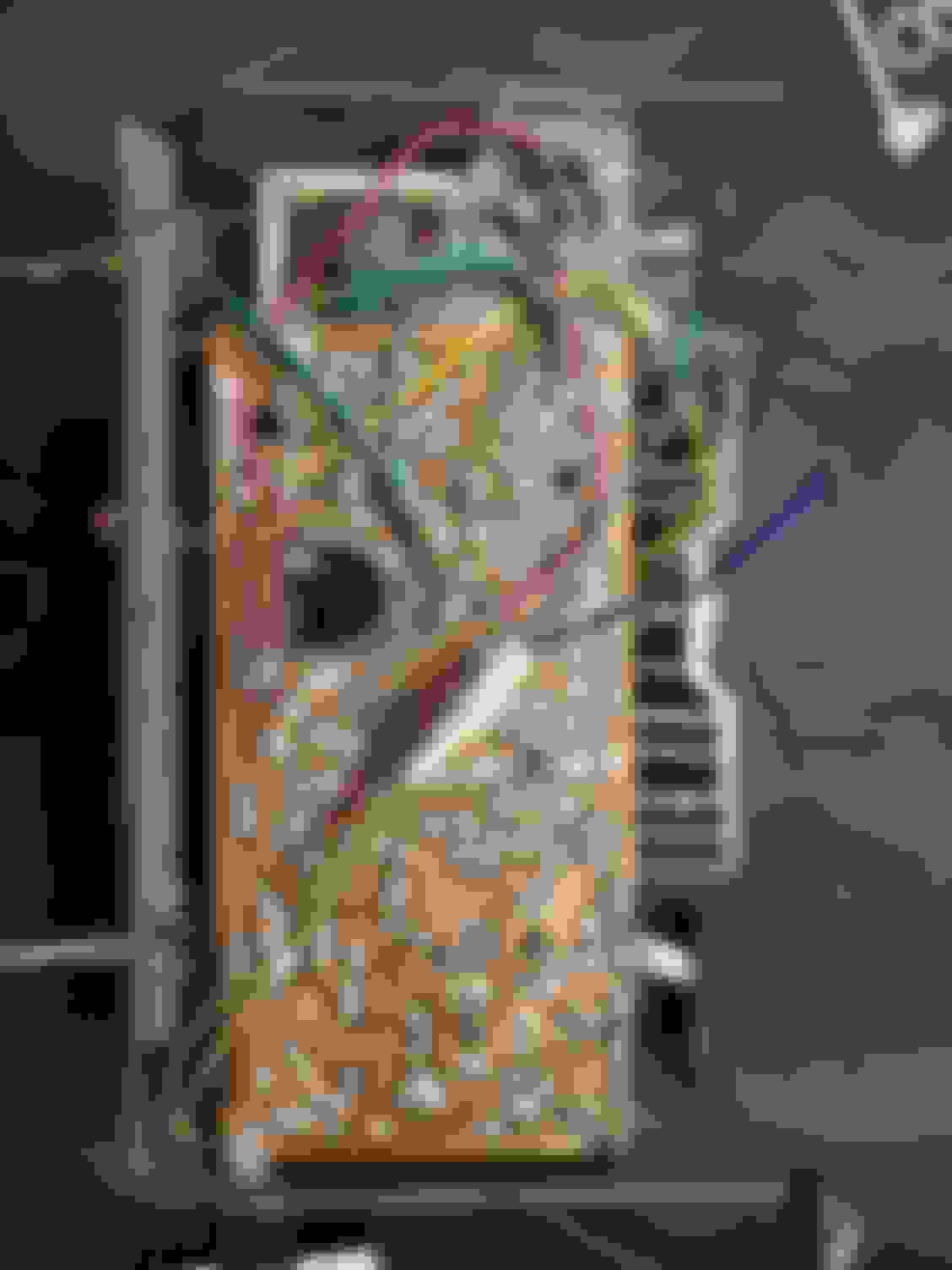
Up-date: I got a good magnifying glass and a light and made a thorough examination of the area on the circuit board where the wire reached comfortably. everything is soldered and silver except one minute spot on the solder where the heavy green wire is soldered. there is a tiny round spot of copper showing that matches the size of the wire. That's got to be the spot.
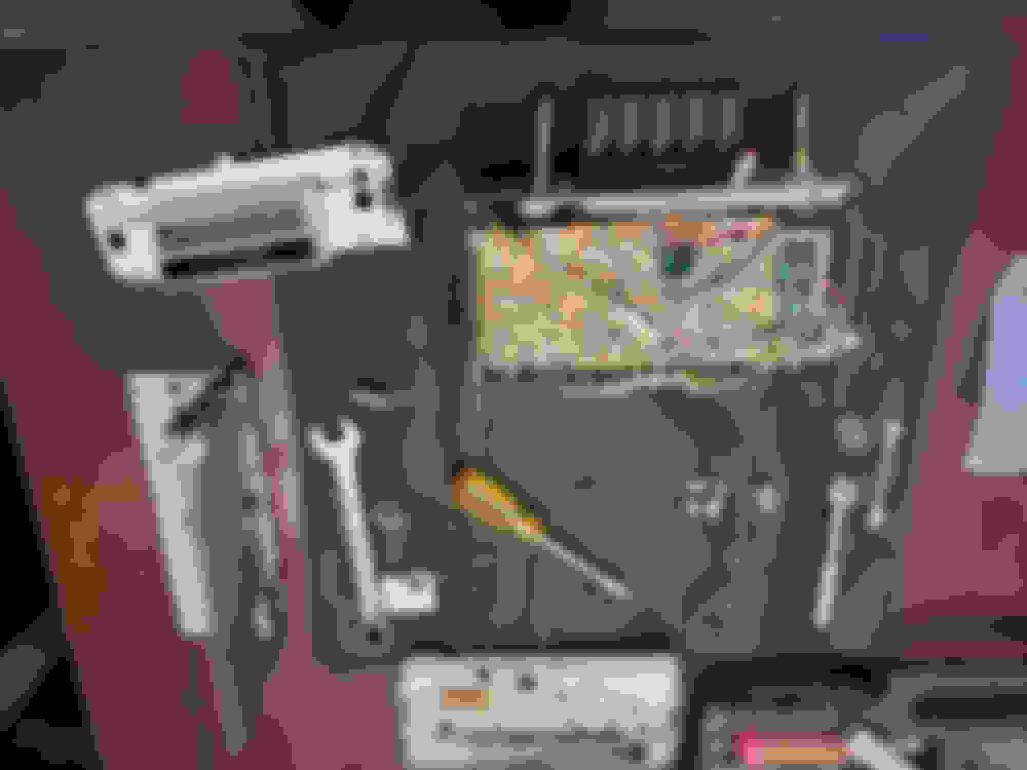
I believe the solder point you've chosen presents a good suspect. However, I'd give myself a fighting chance to learn something from the current wiring. I would (1) remove the white masking tape to visualize the splice (which obviously contains both a blue wire & a dark green wire attached to each of the two old mustard green wires (which someone has obviously had to splice into at some point in time); and, (2) follow those two wires at the splice and see if you can identify what the end-points attach to (my red arrows). At least this way you might hopefully identify the purpose of each.
EDIT: Ooops, I guess the end of my one arrow is not correctly directed to the end of that one wire in my image; you get the point though, see if you can determine what it attaches to and its function if possible.
Last edited by Vintage Chief; January 31st, 2022 at 05:52 PM.
I believe the solder point you've chosen presents a good suspect. However, I'd give myself a fighting chance to learn something from the current wiring. I would (1) remove the white masking tape to visualize the splice (which obviously contains both a blue wire & a dark green wire attached to each of the two old mustard green wires (which someone has obviously had to splice into at some point in time); and, (2) follow those two wires at the splice and see if you can identify what the end-points attach to (my red arrows). At least this way you might hopefully identify the purpose of each.
EDIT: Ooops, I guess the end of my one arrow is not correctly directed to the end of that one wire in my image; you get the point though, see if you can determine what it attaches to and its function if possible.
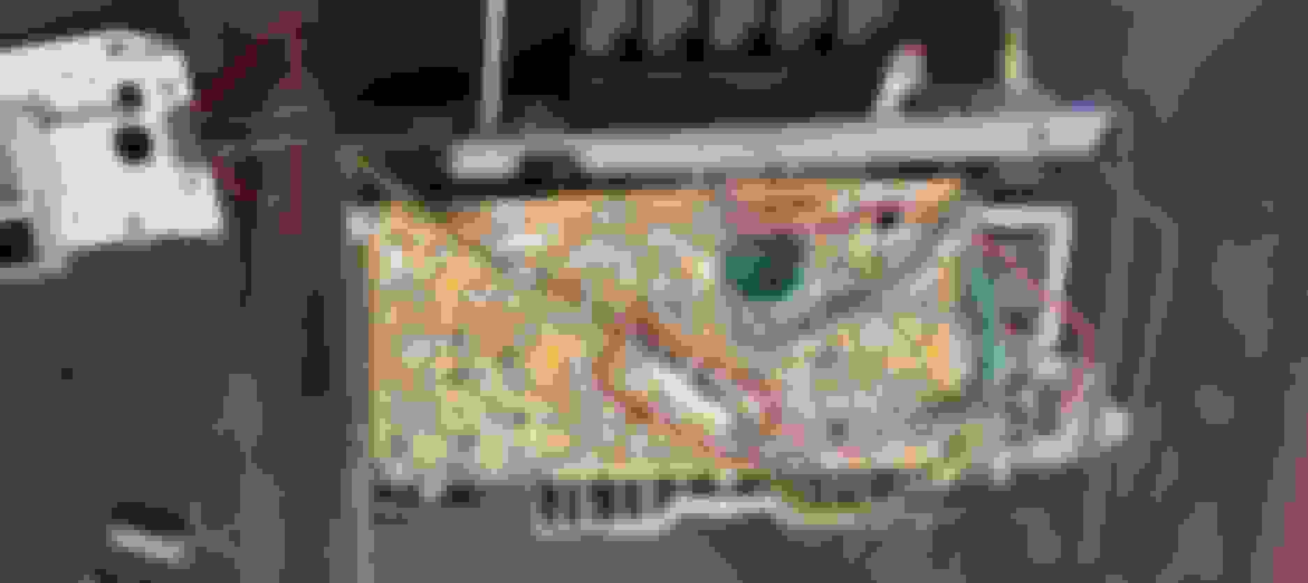
I took your advise and removed the suspect wiring covering. I'll address that now that it's open. The mustard green/green wire runs from the fader to the front speaker out-put plug. The mustard green/blue wire runs from the fader to what I'm thinking is/should be audio out-put (the heavy green wire running to what looks like some kind of coil. The third wire (also blue) runs to the rear speaker out-put.
How soon will you know if you "got it right"? Question, the type of fader used on these old radios - they were simple post faders I believe rather than pre faders - is that your take?
My understanding being a pre fader would apply gain to the original signal prior to being sent to the amplifier & audio output (?), while a post fader would merely manipulate the location (direction - front/rear) after gain/amplification of the original signal(?). There certainly weren't any pre-amps on these old beasts right?
I have owned this car for almost 48 years and have it half apart this winter working on a complete once over. So unless I bench test it, it'll be a while.
They are a simple post fader manipulating the location of the original signal. The same radio was used for cars with either a front or front and rear speaker. One had the fader **** plugged in and other had a dummy **** with a shunt wire pluged in where the fader would have gone. If you look at the 66 dash removal Sticky in the General Post section there is a picture of the front of the radio with the shunt wire installed.

 January 30th, 2022 | 12:25 PM