When you click on links to various merchants on this site and make a purchase, this can result in this site earning a commission. Affiliate programs and affiliations include, but are not limited to, the eBay Partner Network.
I am installing an Edelbrock E-Street 2 EFI system into my '71 cutlass.
I would like to install the ECM behind the battery in the drivers side fender well, however the nice harness that is included with the Edelbrock system is not quite long enough to allow foing this.
So, I would like to find an extension cable or have one made.
If Edelbrock isn't willing to help that is a bummer.
Post some pics. Are you any good with a soldering iron? It should be pretty easy to fabricate an extension your self. The hard part would be if the cable has proprietary ends on it.
You can fabricate your own extension by cutting the harness about 6 inches from the proprietary connector and splicing in your own harness with your choice of connectors.
You can fabricate your own extension by cutting the harness about 6 inches from the proprietary connector and splicing in your own harness with your choice of connectors.
Or, simply extending the original wires with a soldering iron and shrink tubing. What do the connectors look like? Are they standard GM WeatherPak?
Or, simply extending the original wires with a soldering iron and shrink tubing. What do the connectors look like? Are they standard GM WeatherPak?
Thanks you guys for all the responses.
I'd prefer to avoid splicing the harness and would much rather make an e tension that plugs and unplugs.
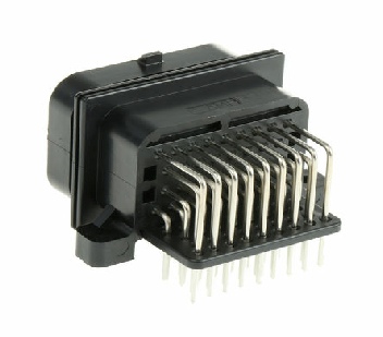
Here are pictures of the connector.
Any idea what they are called, and where I can find them? I'll need a male end and a female end.
Good info, you would think edlebrock would offer an extension harness they have the tools connectors and wires already seems like it would be easy to add to the product portfolio, surely you can't be the first to want to place parts out of sight or convenient for you.
To follow up, these are AMP Superseal 1.5 series connectors. They are designed for motorsports, agricultural, and transportation applications. They appear to be AMP's equivalent to GM's Weatherpak connector series. They are much less expensive if you buy them from an electronics supplier like Digi-Key or Mouser.
So far I've been able to find one end of the connector, the end that is on the existing harness, and thus would plug in to the ECM, but not the end that would be needed to plug the existing harness.
I agree that I couldn't possibly be the only guy who has needed this.
If I can not source both ends of the plug needed to fabricate a sanitary extension harness, I would have to resort to splicing extensions to each individual l
Wire. Anyone have an idea if the added resistance caused by the various solder joints will negatively effect the ECM's ability to read data accurately?
Last edited by Peter Lufrano; June 23rd, 2016 at 10:34 AM.
Reason: Replaced word
So far I've been able to find one end of the connector, the end that is on the existing harness, and thus would plug in to the ECM, but not the end that would be needed to plug the existing harness.
Joe, an excellent suggestion it is. But I'm still not finding the appropriate end on these sites either.
I do see a 26 position version, but not the 34 position version needed.
Apparently Tyco Electronics owns the AMP brand. The female connector bodies in this series are only available in bulkhead mounts designed to either bolt to the side of an equipment box or solder to a circuit board. This is why no one sells extension harnesses.
Apparently Tyco Electronics owns the AMP brand. The female connector bodies in this series are only available in bulkhead mounts designed to either bolt to the side of an equipment box or solder to a circuit board. This is why no one sells extension harnesses.
Yep, this certainly jibes with what I am finding.
Since this appears to be the case, I will need to splice into the existing harness and extend the individual wires.
Any idea if the added resistance from the associated solder joints would negatively effect the ECM's ability to read data accurately?
Any idea if the added resistance from the associated solder joints would negatively effect the ECM's ability to read data accurately?
That will be negligible for a properly-soldered joint. Personally, I'd get new pins for the connector and only have one splice joint per wire rather than two. Also, stagger the splices along the length of the wires to avoid a large lump at one point in the harness. This is for routing and esthetics, not functionality, however.
Anyone have an idea if the added resistance caused by the various solder joints will negatively effect the ECM's ability to read data accurately?
Done carefully I wouldn't expect an issue. My preference is to use barrel crimps, then solder them to seal, then use shrink wrap. I use adhesive lined shrink wrap if it's outside the passenger compartment.
The key is the true electrical connection comes from the crimp - it has to be a correct crimp, not from pliers or the $5 stamped tin crimpers. There's actually some cool physics that happens with a strong crimp.
The solder keeps it sealed and lends a little strength. Have to be very careful to ensure the solder doesn't climb up the wire (makes it fragile) and there's not an overly large gap between the insulation and the barrel.
That said, it's overkill. A good solder with tightly twisted wires will do fine. We're not dealing with particularly high frequency signals (or even slightly high frequency, really). A notable resistance will skew readings, but it would have to be a pretty poor, or failing, soldering job to be significant. (*) Solder-only connections can be fragile and sensitive to vibration, so just make sure it's secured well and won't be yanked on.
Another option is to disassemble the harness and rebuild it using longer wires. I fully expect the pins can be readily sourced, then just have to get appropriate TXL/GXL wire. If you're a sadist then use only black wire. No soldering necessary, but need the right crimper. Also get a custom fit harness that routes and lays however you want and get rid of any unused wires!
(*) My favorite one so far: I was working on a neighbor's '49 Chevy truck with a '96 LT1 and a '81 Camaro steering column. For the NSS they took the starter solenoid wires from the column, firewall connector and the NSS switch, each about 8ga, tinned about 1/2" of each end, then just laid them alongside each other and globbed on a wad of solder. So ALL of the electrical connection was through a glob of solder that went around the wires. *sigh*
The key is the true electrical connection comes from the crimp - it has to be a correct crimp, not from pliers or the $5 stamped tin crimpers. There's actually some cool physics that happens with a strong crimp.
The solder keeps it sealed and lends a little strength. Have to be very careful to ensure the solder doesn't climb up the wire (makes it fragile) and there's not an overly large gap between the insulation and the barrel.
Not sure where you get this info from, but it is not correct. A properly soldered joint will conduct as much as a crimped joint, and is generally not subject to vibration separation. Also, solder does not make wires fragile, but it does make stranded wire stiffer.
Last edited by RandyS; June 24th, 2016 at 07:31 AM.
That said, it's overkill. A good solder with tightly twisted wires will do fine. We're not dealing with particularly high frequency signals (or even slightly high frequency, really). A notable resistance will skew readings, but it would have to be a pretty poor, or failing, soldering job to be significant. (*) Solder-only connections can be fragile and sensitive to vibration, so just make sure it's secured well and won't be yanked on.
When soldering, you do not twist the wires together, you tin both ends and lay them side by side.
Another option is to disassemble the harness and rebuild it using longer wires. I fully expect the pins can be readily sourced, then just have to get appropriate TXL/GXL wire. If you're a sadist then use only black wire. No soldering necessary, but need the right crimper. Also get a custom fit harness that routes and lays however you want and get rid of any unused wires!
(*) My favorite one so far: I was working on a neighbor's '49 Chevy truck with a '96 LT1 and a '81 Camaro steering column. For the NSS they took the starter solenoid wires from the column, firewall connector and the NSS switch, each about 8ga, tinned about 1/2" of each end, then just laid them alongside each other and globbed on a wad of solder. So ALL of the electrical connection was through a glob of solder that went around the wires. *sigh*
his is the proper method of soldering wires ensuring there are no sharp edges that will poke through the heat shrink. For a harness, as Joe stated in an earlier, you must stagger the solder joints to not create a huge lump in the harness.
 June 22nd, 2016, 01:51 PM