When you click on links to various merchants on this site and make a purchase, this can result in this site earning a commission. Affiliate programs and affiliations include, but are not limited to, the eBay Partner Network.
I'm in the middle of a CK build. Started with a CQ5 core. It's going along well, but I've got a growing list of questions that hopefully I can get some assistance with. So to start off, everyone likes pictures:
Currently, i need guidance on direct and forward clutch pack clearances. ive seen anywhere from 20-60 thousandths for the FWD and 40-70 for the DIR. im using kolene steels (FWD: 0.071, DIR: 0.092) with the following arrangement:
If I use a 0.092 DIR steel in place of one of the FWD, it goes down to 0.041; and if I use two, down to 0.020 - which clearance is preferable: 0.062, 0.041. or 0.020?
DIR stack: DIR steel - frict - DIR steel - frict - DIR steel - frict - DIR steel -frict - DIR steel - frict - DIR steel - frict- pressure plate: clearance = 0.068 is this acceptable? If not, what options do I have for playing with this number? I'm assuming that the pressure plates in selective sizes are no longer produced/available.
Another thing that I've been thinking about is lock up. This trans will be going in a '72 supreme vert that I will be using for long highway cruising and top end rolls. I want to get gas mileage and low RPM cruising, but I also want it to pull in third and even fourth if that is what I need to get to my top end. I will install the fourth gear lock up switch on the valve body, but I'm wondering about the utility of having brake, vacuum, and manual switches/controls in the circuit as well. Thoughts?
Also, does anybody know if there has been a write-up for column gear selector indicator mods when going from 3- to 4-speed? How about if I want to install cruise into a non-cruise column shift column?
The forward clutch clearance isn�t really all that critical. The only drawback to running the clearance tight is the car might have a tendency to �creep� slightly in neutral. As for the direct, what does CK performance recommend? I don�t have my CK manual handy to look. Rule of thumb, .010-.015 per friction. So 6 clutches, .060-.090 should be good. I think your .068 is pretty close to ideal.
As for your lockup converter questions; most converter clutches aren�t designed for full throttle application. There isn�t enough surface area, the clutch can and probably will slip. They do make multi-disc converters, but they are much more expensive.
I built the steering column in my car from a bunch of parts. I started with a column from a 75 cutlass, it bolted in with zero modifications. I�m wondering if a B body column set up for a overdrive trans (the internal shifter gate will have detents for 4 forward gears) and will be able to use a later model turn signal lever with cruise controls. Epoxy the wiper switch solid, cut the wiring to the delay wiper switch, and use the cruise lever to control a aftermarket cruise control kit ( I have the Rostra setup on my 69). Use the column mounted dimmer switch to control the headlights, and use the original floor mounted dimmer for the lockup converter.
Thanks for all the ideas, Matt - gives me a lot to think about.
Clutch clearance: in the CKP manual im referencing (2nd ed) its FWD: 20 - 30; DIR: 30 - 65. I'd heard the 010/friction rule and that's why i asked. Seems like the CK build are a bit tighter. I'll leave the DIR at 068 and add one DIR steel to the FWD to make it 041.
Lockup: Yeah, that's why I was asking. I don't really understand it all, but the way I understand it is that it's best to not have the converter locked during WOT. The CK build provides for the fourth gear switch on, but I was thinking that maybe I would want a manual switch, or vacuum controlled switch to turn the lockup off when I want to wind it up. i like the floor dimmer switch idea. any chance you have a drawing of how you wired it?
Column: Looks like I've got some research to do. I'm not against swapping columns, nor having later model functionality (actually, intermittent wipers would be very welcome) but I would like to try and keep it looking somewhat period correct. Does anyone know what model/year they started offering OD transmissions? Looked at the Rostra, it looks great for the price. I was kind of trying to keep everything analog, just because. But, I may have to be practical about it.
FWIW, I used a Kugel adjustable shift arm kit on my '68 column when I converted from a Jetaway (PRNDL) to a 200-4R (PRND321). With proper adjustments to correct the swing-angle ratio of the 200-4R's shift arm, I was able to get the PRND indicators, gates and neutral safety switch to line up w/ the trans' detents. I have to rely on counting detents to know if I'm in 3-2-1 because my shift indicator is blank in that area, but there's no "gating" within the column that prevents motion past "L".
For sure, put a brake-light triggered relay in series w/ your lock-out power feed, and if you are planning on a lot of WOT in lockup, a vacuum switch is needed as well. It doesn't need to be any more complicated than that unless you want manual control over lockup.
At one time during the 64 F-85 construction I was going to use my column shift and had bought a Kugel shift arm kit. I found that the little plastic shift gear indicator piece from a later 68 ( cannot remember the exact years) on up Nova fit right in its place so you see what gear you actually were. Since then I changed it over to a B@M Bandit floor shifter. I have the parts around somewhere bagged and put away.
I have not changed the indicator on the column of my 66 but D is actually overdrive and in between D and L is third and I keep mine there unless I am going above 50 as fourth/overdrive would be just off of idle at that point with the 355 gears I have. I drove about 200 miles yesterday and used less than half a tank of fuel while cruising at 75-80 miles and hour. You will for sure enjoy having the overdrive in your car. We used a lokar linkage kit to hook up the transmission to the column shifter. My 2004R shifts hard and has a manual valve body with all internals being billet now. I can break the tires loose in the first three gears if I put my foot down. We thought it would be best to make the trans as close to bulletproof as possible as the drum and shaft broke at the weld on the first test drive so we overbuilt it on the second rebuild for safety.
You can trade the "ring" that is in the piston on that direct with the other one and see where it gets you. You
could also get .106 steels that could replace some or all of the steels. There are also thinner steels but I wouldn't go that way as a thinner steel can get over heated easier and that isn't good.
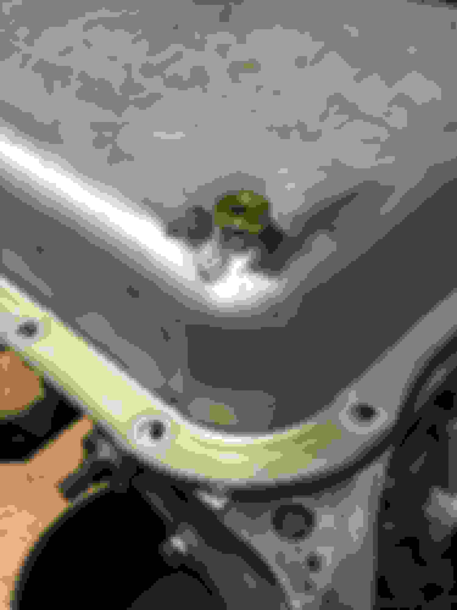
Started final reassembly, waiting on a few selective washers to get end play right. I wanted to share a method that I used to get the lo/rev clutch housing in, because I had such a hard time with it. I guess it's possible to get it positioned without a special tool, but I couldn't get it in by hand. So, I made a tool out of a length of 2" exhaust pipe that I radiused down on the belt sander, and polished a bit by hand. If I had a lathe, I would've just turned it to whatever the diameter of the sun gear bushing journal is, but I don't, so I just did it by feel. I made it so it would slip into the l/r clutch housing as a snug interference fit, that way I could hold it and position it into the bore of the case, but not so tight that I couldn't slip it back out once the housing was in place:
The tool worked out well to position the housing and make the tiny adjustments needed to get it lined up with the lugs in the case. So i took some time to sand down any rough edges on both the case and housing with 600 grit and put the housing in and out about 50 times to where I got a "feel" of where I could pretty much drop the housing into position in the empty case with a nice "click." The problem I kept running into was when I did final assembly. I'd install the output shaft using the adjustment tool (I bought that one - glad i did), then the rear carrier, and when it came time to put the l/r housing in - it would slide in nicely but get hung up on the lo roller race. No matter what I did, i couldn't get the splines on the housing to line up and drop in. I spent almost 6 hours making all kinds of minute changes trying to get it in to no avail. So, out of desperation, what I did was pull out the output shaft, remove the lo clutch pack and on the bench assemble the shaft, carrier, and housing together, then removing the adjustment tool, I turned the case horizontally, and carefully put the whole assembly in that way. Only after I was able to slide the housing snugly into its proper position with a nice click (only took 5 seconds) _then_ I installed the output shaft adjustment tool to secure the assembly in position. Then I rotated the case back to vertical and carefully took the housing back out using my tool. Carefully reinstalled the clutch pack, and using the tool again put the l/r housing in no problem - went right in.
I understand that my lack of skill probably contributed to this hassle, but even if I had had the good metal remove/install tool, I don't think it would've helped with the alignment of the sprag teeth with the splines on the housing - that was because by "fixing" the output shaft and carrier in place with the adjustment tool prior to having the housing set in place - it made it impossible to line up. Again, maybe just my ignorance - but it worked for me.
As I'm getting closer to buttoning up the trans, I decided to get to the pan modifications. I added the drain plug - my welding still sucks, but I am getting good at grinding.
as i was finishing the plug i thought to myself, since I was doing such a poor job of welding the drain bung onto the stock pan of my non-ECM 2004R it occurred to me that maybe somehow instead of having to do a hack job of welding a tiny 1/8 NPT temp sender bung into the pan, that maybe the temp sender could be attached inside the pan and the wiring to the gauge routed to the case connector that has the 4th pressure switch wiring - from there up to the dash. The temp sensor threads into the 3rd pressure port on the VB, which in my case is not used. My question: is it possible to route the right kind/amount of oil to that bore enough to run the temp sensor? Probably a stupid idea, but it might save me from a grind-fest with the dremel after I jack up the weld.
So, I was told that the temp sensor in the VB idea wouldnt work, so I just went ahead and welded it into the pan. The trans is pretty much reassembled and ready to be installed into the vehicle. all the air checks seem to be a 'go.' all i need to do is finish the lock-up wiring. what ive decided to do is use the solenoid that CK supplied which has the 4th switch on the ground side in the VB. i'll add a brake lever switch and vacuum switch on the line side. The problem im having is that i thought to test the solenoid before buttoning the trans up. I connected the + side of a battery to the red wire going to the solenoid, and the ground to the black - result was sparks and hot wires, no clicking sounds. Any suggestions as to what is happening?
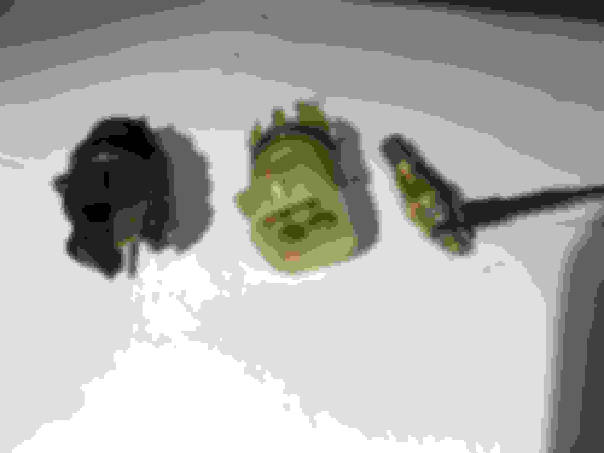
Also, ive got to get some wiring connectors, does anybody know part numbers for pigtail connectors for the connectors in the pic? Also, does anybody know if anyone makes some kind of weather seal boot that will go over the temp sender wiring (also in the pic)?
The center connector is just a four terminal square Weatherpack pigtail, available anywhere Weatherpack pigtails are sold. The two terminal kickdown connector will be difficult. I'm not aware of anyone who reproduces these. The two-wire trans pigtail was only used on the 1964-67 Buicks and Oldsmobiles with switch pitch and on the 1970-72 cars with Transmission Controlled Spark. You can get the single wire TH400 pigtail as repro, but not the two wire. There are round push-on terminals for that temp sender. On the other hand, you might be able to use an old spark plug wire boot from the distributor cap end of the wire. HEI boots are probably the best to use for this.
So, I was told that the temp sensor in the VB idea wouldnt work, so I just went ahead and welded it into the pan. The trans is pretty much reassembled and ready to be installed into the vehicle. all the air checks seem to be a 'go.' all i need to do is finish the lock-up wiring. what ive decided to do is use the solenoid that CK supplied which has the 4th switch on the ground side in the VB. i'll add a brake lever switch and vacuum switch on the line side. The problem im having is that i thought to test the solenoid before buttoning the trans up. I connected the + side of a battery to the red wire going to the solenoid, and the ground to the black - result was sparks and hot wires, no clicking sounds. Any suggestions as to what is happening?
Also, ive got to get some wiring connectors, does anybody know part numbers for pigtail connectors for the connectors in the pic? Also, does anybody know if anyone makes some kind of weather seal boot that will go over the temp sender wiring (also in the pic)?
Your square plug TCC solenoid pigtail connector in the center, if it's a typical and widely used 3 pin, is GM p/n 12085533. Or Dorman makes an aftermarket equivalent. I believe you mentioned using a CQ out of a Monte SS I believe? Good core.
If anyone requires a 4 pin TCC solenoid pigtail connector, like the Buick GN, BRF coded transmissions had, GM also sells a 4 pin version of the plug, p/n 12085506. There's a 12V wire to the TCC solenoid, a ground, a 3rd gear switch plus a 4th gear switch on a BRF. There's likely other uses with the 4 plug as well, but that is the only 200-4R one I know of.
Last edited by 69HO43; June 22nd, 2020 at 06:11 AM.
You should be able to bench test the solenoid just like you did - one side positive, other side negative, straight to the battery. Anything more exciting than a "click" should be investigated!!
Thanks for the info, guys. I went ahead and just ordered the 3-pin weatherpack. I really only need one pass through connection, but it�s the easiest solution. Not sure why the vendor sent the two spade connector given it�s rarity, and the fact that the kit only requires one connection.
i think the problem I was having testing the solenoid was operator error (at least partially). When I set the test up by grounding the battery neg to the VB, then ground the solenoid to a different spot on the VB - it functions as it should. I�m not sure why connecting the solenoid ground lead directly to the battery neg terminal apparently caused a short. I also realized that the solenoid needs a bit of back pressure to actually function, otherwise the pin just falls into the �down� position with no need for electrical assistance. That�s why I wasn�t hearing a click. When I blew into the stem of the solenoid, forcing the pin up as an oil pressure load would do, then connected the circuit - hearing the Solenoid engage was very apparent.
next question has to do with the brake switch for the TCC. I recently bought a cruise set up to install at some point. It also utilizes a brake cut-off. Is there any reason why I couldn�t jump a lead from the N.O. part of the switch to run as a parallel brake switch for the TCC? If so, any recommendations for connectors, or do I just solder the TCC lead to the cruise lead?
along the same lines, it looks like there are basically two choices for vacuum switches for the TCC cut-off circuit: Delco 212331, and the adjustable Superior K058. I like the idea of being able to dial in the switch, but I�ve read bad reviews about the J058. Appreciate any recommendations.
Looks like I spoke too soon (another one of my bad ideas). Looking at the cruise wiring harness, the 12vdc line goes from the fuse block to a switch on the dash, then to the brake. So, I can�t use that power source. I�m wondering if I can still use the single brake switch for both circuits (TCC and cruise shut off) somehow?
I�m wondering if I can still use the single brake switch for both circuits somehow?
The converter lockup needs power when the brake is released. The brake lights need power when the brake pedal is pressed. What do you think?
The only way to do this is with a normally closed relay powering the converter solenoid that is controlled by the brake pedal switch and opens when the brake pedal is pressed.
If i understand the assembly manual, it is a two-way switch. the front side is N.C. for the cruise, and the back side is N.O. for the brake lights. I was thinking that maybe I could use a relay somehow powered by the front part of the switch to power two circuits that need to be turned off when the brakes are applied (cruise and TCC). The problem is that the power to the cruise must be switched on first by the driver, while the power to the TCC is always on.
Last edited by adis; June 22nd, 2020 at 06:49 PM.
Reason: spelling error, incorrect reference
If i understand the assembly manual, it is a two-way switch. the front side is N.C. for the cruise, and the back side is N.O. for the brake lights. I was thinking that maybe I could use a relay somehow powered by the front part of the switch to power two circuits that need to be turned off when the brakes are applied (cruise and TCC). The problem is that the power to the cruise must be switched on first by the driver, while the power to the TCC is always on.
just get a brake switch for a later car that has a TCC converter, it will have the correct configuration of contacts. The early computers on the first TCC equipped vehicles weren�t fast enough to lock/unlock the converter in relation to brake switch/driver input. Once certain parameters were met (engine temp, vehicle speed, transmission gear) the ecm would command the converter to lock. The brake switch and usually a vacuum controlled switch would unlock the converter far faster than the primitive computer could.
I know the brake switch for my 81 GMC 1/2 ton truck had the switch you need. Go to your nearest parts store with your electrical meter and try a few different model switches. As long as one set of contacts are open, other closed, then changes configuration when you push the switch, it should work fine.
FWIW, I use a cruise brake switch as part of my torque converter lockup system. Just like you expect - use that as primary feed so the system is disabled whenever the brakes are depressed.
I use a vacuum switch connected to ported as the next interruption in the power line - only provides power when I'm applying moderate throttle (zero vacuum when off the gas, low vacuum when accelerating).
Last trick was using the 4th gear switch as a trigger to a timer. If the above conditions are met, then the timer is powered. Once 4th engages, the timer counts down 8 seconds. If everything still good, it engages the clutch. Clutch disengages if any condition not met.
Working out quite well, but still hunts around 45mpg, so I normally leave it in 3rd driving around town.
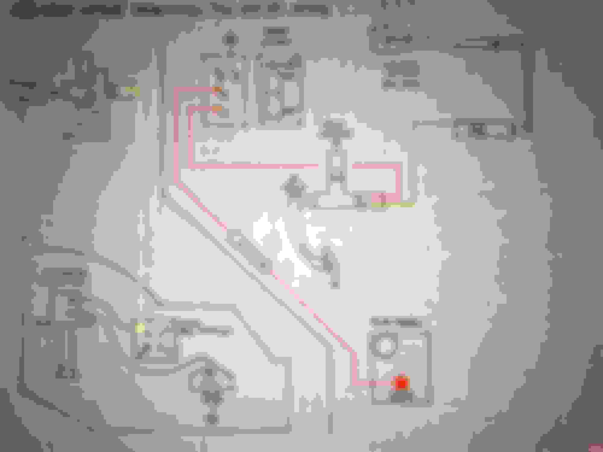
Admittedly, I am a kindergartener when it comes to electronics, but I've put some thought to how I'm going to wire this up and here are the two solutions that don't require anything more than soldering some leads. First, I wire the cruise according to the manual, and jump the TCC shut-off circuit to it at the brake switch. What this essentially does is add a manual switch to the TCC circuit, so that I have to turn it on if I want to lock up (and use the cruise). I suppose there may be benefits to this, although I'd rather not have to think about turning the lock up on. But, given my driving habits, I suppose that much of the time, when I desire one - I'll likely desire the other. However, I'm just not sure it it's advisable to drive around with the cruise enabled (on) but not set to a speed (that's done with the column switch. The schenatic as I understand it:
The second option is to reroute the cruise wiring and have 12vdc power go directly from the fuse block to the brake switch. This way I can jump the TCC circuit into it before it goes to the cruise dash switch. From the brake switch, power then goes to the dash switch, and finally to the column switch. Not sure if rerouting the path by putting the brake switch upstream of the dash switch will have detrimental effects on the operation of the cruise system or not. A drawing:
Not decided on the delay for the TCC 4th oil switch, I'll have to consider it more. Also, any recommendation on which vacuum switch to use - I need to order one soon.
Thoughts, flames, suggestions all welcome. TIA - adis
All the vacuum switches are the same thing. They're adjustable. The 0-8" vs 8-20" difference is which terminal on the switch you use. It's the same thing just sold under different part numbers and different brands. Find the cheapest one you can. I saw a dramatic range of prices when I got mine.
Either diagram is probably fine. I don't know how much current is pulled through the cruise system, so that would be my only concern with #2. Those brake switches are fiddly little pieces of junk.
So I had the stock D5 converter rebuilt for this application. I�ve seen different numbers for what it stalls at, I�m going with 2050 rpm. Currently, the supreme still has the stock 350 with a few bolt-ons, so it�s prob at just about the same power level as the �85 MCSS that the trans came from. CK told me to get 3 things done to the converter: roller bearings instead of thrust washers, a woven fiber lockup, and a one-piece pump drive hub. The rebuilder had the roller bearings, but he said that he didn�t use fiber lock up frictions because he�s seen them break - he only uses high carbon. Not sure what that means, but I trusted his judgement. He had to order the hub, and you can see in the pic where he welded the new one in. Didn�t really understand what The hub is or what Improvement it being in one-piece offered, can anyone explain it - is it for improved strength?
It must be a strength thing with the hub. I have the TCI lock up kit with the adjustable vacuum switch. With the stock cam it works perfectly. The switch is super sensitive as far as adjustment. It took a bit of playing with the adjustment with a 214/214 cam. Otherwise it hunted up and down constantly. I also plan on building one of my 2004R'S to handle serious power within the next couple of years. You basically need to move your crossmember back to the TH400 position and modify or get the TH400 emergency.brake cables to do the swap from a TH350, it is that easy.
Yeah, I was pleasantly surprised at how smoothly the trans went in (I did it by myself) with a sturdy 3 ton floor jack. The only bummer is that now the car has metric nuts/bolts on it - just an annoyance of mine. I�ll have to carry metric tools in the toolbox when I go in long road trips. Didn�t know about the 400 E brake, thanks for the tip.
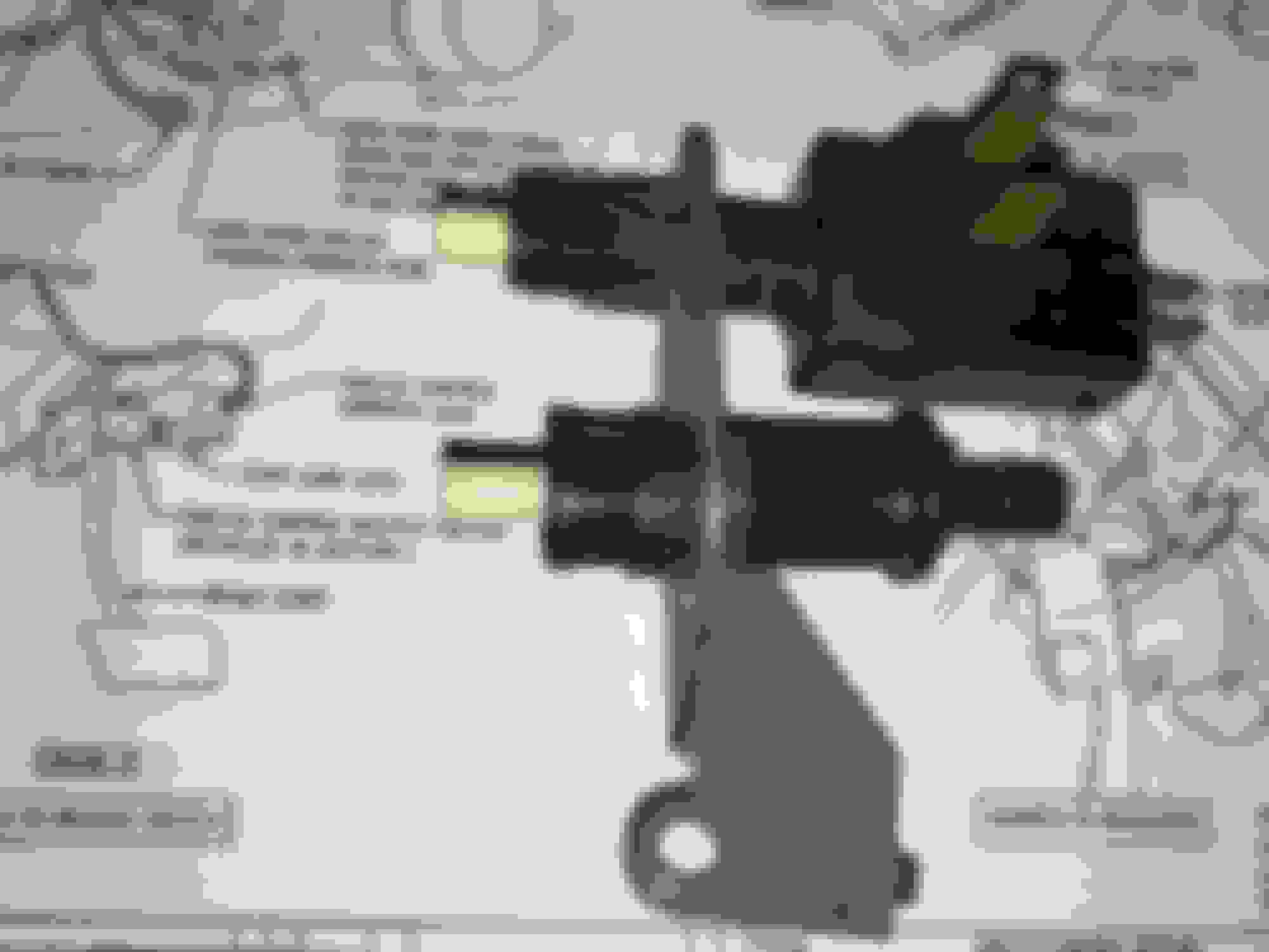
So I took Matt�s advice and looked up other vehicles with TCC switches, and it turns out that a �95 Supreme has the exact brake switch I need - one normally off, and two normally on:
not sure what type of trans that particular vehicle had, but the switch should work just fine. I tested the two normally on circuits to ensure that they are separate, which they are, and the threads fit into my bracket. I spent too much money buying Factory connectors when I could have just used simple Push-on connectors, but I didn�t want to cut the existing harnesses, and I�m happy with the way it came out. I haven�t hooked up the cruise yet - that�s a project for the next pandemic.
Oil cooling: I spent all day Tuesday ruining two sets of pre-flared lines trying to bend them to fit. I resigned myself to my ineptitude and splurged for stainless braid flexible hoses with -AN fittings. Pricey, but What a dream installing them. Just for good measure, I went with an external cooler mounted to the radiator top plate. My coolant temps tend to rise in stop and go traffic when the weather is above 80* or so. I�m hoping this will help with that, until I can install dual electric fans:
next, dipstick/tube. I�ve decided to use the th350 tube from the old unit. I�ve read alternately the tube �reads a quart full� or that I need to shorten the th350 tube by 0.75� in order for the dipstick to be correct. I presume that those two statements corroborate one another, and that a quart of oil in the pan of a running 2004R equates to approximately 0.75� on the dipstick. I mention this because if you take a look at the pic above, you�ll notice the CK pro-street build includes a pan spacer and extra gasket to accommodate a 700R4 filter (I think). This adds about 0.1875 - 0.25� added depth. So, can I assume that if I shorten the fill tube by 1.0� the markings on the th350 dipstick will reflect the actual level in the pan? I suppose I should consult with CK to find out, because maybe I�m supposed to just add fluid to offset the deeper pan, and the markings on the stick read the same as if there was no spacer...need to look into that.
Also, based on what is shown in the pics, any reason I should add oil because of the oil cooler and new lines. My thought was that the little air to fluid cooler I installed probably holds a similar amount to the fluid to fluid cooler in my radiator, so no need to add any oil beyond the 11 quarts. But, my cooler lines are slightly longer and slightly bigger diameter than stock..,who knows?
Last edited by adis; July 10th, 2020 at 10:22 PM.
Reason: Clarify
It just occurred to me that I need to put a fuse in the TCC circuit (it�s drawing from IGN, which I believe is not fused). Anybody know what size fuse I ought to use? It�s just the solenoid in the VB - 0.5A???
Decided to fab the throttle lever using parts of both levers. I used the shaft keyhole from the TV lever to ensure that it�s geometry is correct.
Still doesn�t fit because the adjustable TV cable set screw stop hits the cruise bracket preventing the throttle shaft from fully rotating to WOT. I�m going to try and find a smaller, crimp-on stop like the one that is at the end of the cable) - any idea where I could get smth like that (could I just crimp on a small section of copper/aluminum tube?)
Which brings me to the main question: the vendor sent me a TV cable that is slightly different from the one that seems to be preferred. It�s Teckpak part number: K77978. It doesn�t appear to have the ratcheting fine adjustment that I see demonstrated in all the �how to� videos I�ve watched (and, ironically, which is also used in the vendor�s rebuild guide...) It does appear to have the ability to adjust the cable sleeve back and forth (1.5� in total). is this all that is required? Are the installation/adjustment instructions the same as the ratcheting type? Thanks for any info.
It looks like a ratcheting type, although it may not be an automatic setting one like the common replacement. See the tab sticking out of the mount block? Push that in and you can slide the sleeve forward and backward in relation to the mount.
You can also get the self setting style, which you've seen. It's a ratcheting type. The only special thing is you pull it all the way back (forcing TV full open as early as possible), then stomp on the gas pedal. That forces the sleeve forward when the TV valve bottoms out, but the throttle keeps moving. Once it stops moving, it's set.
Then there's totally manual ones like the Lokar cables.
All that matters is that WOT is set correctly - and don't be fooled, it can take a fair bit of force to fully seat the TV valve. The geometry of the arm then sets the resting point at idle. When in question, it's best to set and then verify idle and WOT TV positions at the trans with the pan off. Obviously a messy two person job. The Extreme Automatics guys have the best instructions I've seen on their 200-4r tech page.
I like to use bike brake/shift cable ferrules to cap off small wires. You can get them in lots of colors, too! But for something like this you have to make sure you get it in exactly the right place.
Adis:
My trans builder provided that same TechPak TV cable with his rebuild. I found it to be about 15" too long, so I purchased a Pioneer CA-1937 which fits much better. I'm using a Q-jet throttle bracket from an '88 Olds 307. Make sure the cable has no slack at idle. You want the trans pressure to jump up at the least little throttle movement.
Rodney
I agree and have used that cable, not auto setting. I liked that unlike the stock cable you can easily adjust the tension. Be warned once you tighten the cable front clamp on the end it will mushroom the cable making it hard to adjust again.
Finally got the throttle bracket, cables, and spring sorted out (well, mostly) and mocked up the TV cable. What I did was pull the adjuster out mid-way, then set the cable length for WOT. I cut the cable and soldered a ferrule onto the end (instead of using the barrel clamp, so it would fit behind the cruise linkage). I figured this way I would have room to move the adjuster in/out depending on how the cable felt at the idle position. So, for some reason I was thinking that the plunger should be fully released when at idle. But, I think I had that wrong and the plunger should be stroked a bit at idle (like 3/16� travel into the bore). Is this correct? The EA website mentions that the plunger should be 0.840� out of the bore at idle, which mine is, but they also caveat that with the statement that the measurement only applies to their transmissions.
I think there is a specific line pressure everyone is looking for with the TV connected and engine at idle. If the pressure is too high, you can have problems like 2nd gear start or lazy part downshifts coming to a stop. As long as the pressure at idle is acceptable (I THINK the pressure is suppose to be 90psi?) and the TV plunger maxes out at WOT, that�s probably within acceptable limits. A test drive will be needed to verify the other shifting characteristics
Most important items:
1) Plunger is fully seated at WOT
2) Pressure rise test works like EA says (car in gear, fast idle, watch line pressure on a gauge, should immediately rise when touching the gas/TV cable)
The plunger will NOT be fully extended at idle. It will be pushed in some.
Specific pressures depend heavily on the combination of springs used by the builder. So a specific number may not be helpful.The key is that the line pressure rises with very little TV movement. If line pressure stays at its lowest for ""a long time"", then the trans will burn the clutches due to low line pressure.
So I finally got everything else done and turned the key on this 200-4R build/swap. My initial pressure tests and road test are worrisome. Build used 0.555 boost valve and 0.300 reverse boost valve, CK pro street build. Did pressure test with rear axle on jack stands wheels spinning free, so I presume governor was in play (stock MCSS gov: lightest stock weights only one spring). TV pressure climbs immediately on acceleration. Seems like pressures are too high:
gear/600/1000/WOT/note
P/90/100/270
R/175/210/250
N/90/100/285
D/90/115/257/shifts @ 20 & 40 mph
3/90/112/257/shifts @ 20 mph
2/90/112/257
1/can�t get shift lever down that far
Did a road test and I couldn�t feel a 1-2 shift, possibly starting in 2nd (or maybe I just don�t know what it�s supposed to feel
like - I was expecting a very noticeable 1-2 shift)? Is there any way I can adjust the column shift lever linkage to allow shifting into manual first, or do I have to tear into the column and remove the shift detent plate?
Why do I feel a shift in manual 3rd?
Why isn�t my manual 2nd pressure high? (Intermediate servo clearance: 0.125�).
Lots of other questions but I�m not entirely sure what I�m seeing, so first things first. Any suggestions as to how to start troubleshooting are appreciated- Mark.
Just read on the CK website that their pressure regulator valve group is designed to increase pressure to 90/290 - so it looks like I�m good there. Still trying to figure out 1-2 shift and lack of manual 2nd pressure.
If you put the shifter in 1st at the trans, do you get first gear? I don�t have my CK book handy, I seem to recall that 90psi is the textbook spec for idle with the TV cable unhooked. Much more than that and you can have issues with 2nd gear starts, no downshifts, etc. I would expect the pressure to rise at 1000, due to the added throttle pulling the TV cable further, and added pump volume. The pressure in the manual gears do seem a little high, once again I�m going by memory so maybe they are ok.
Column shift? Are you using a conversion kit? You need different geometry to get the full P-1 sweep out of the stock three speed column. We used a universal rod kit from Shiftworks on the '70 Chevelle (bench, column shift, 200-4r) - works out pretty well.
Both 200-4r's I've worked on had extremely noticeable 1->2 shifts. You'd get a loud pop/slap/bang as the band grabs the shell and gives the trans a good twist.
My 200-4r that failed did so by slowly losing 2nd. Took a while to figure out, but it would essentially hang in 1st (2nd would "engage" but the band was totally dead) then jump to 2rd. Get the linkage fixed and figure out what gears you really have.
I can't remember the M2 pressure readings on mine. Otherwise, those pressures look fine.
Spoke with vendor - the kit I installed deletes the Low boost so I actually shouldn�t see any pressure increase in M1 and 2.
Had me adjust the outboard end if the servo apply pin to 0.80� from the clip - this softened up the 1-2 shift a good bit.
I am experiencing a modulation in transmission rpm (I think that�s what it is) in either 3 or 4 (prob 4 cant really tell) at specific part (Light) throttle. It�s a surge then drop then surge then drop - continues In a regular pattern until I hammer accelerator or manual shift lower. Any ideas what this is?
Other than that, I believe this trans will get the Cutlass from MD to OH at the end of the month. Kinda sucks that I spent 6 months and probably +$2500 to get the trans to this point and now have to mothball it for 3 years. But I really appreciate everyone�s willingness to help. Definitely couldn�t have done it without CO assistance! - Mark
 May 2nd, 2020, 09:26 PM