When you click on links to various merchants on this site and make a purchase, this can result in this site earning a commission. Affiliate programs and affiliations include, but are not limited to, the eBay Partner Network.
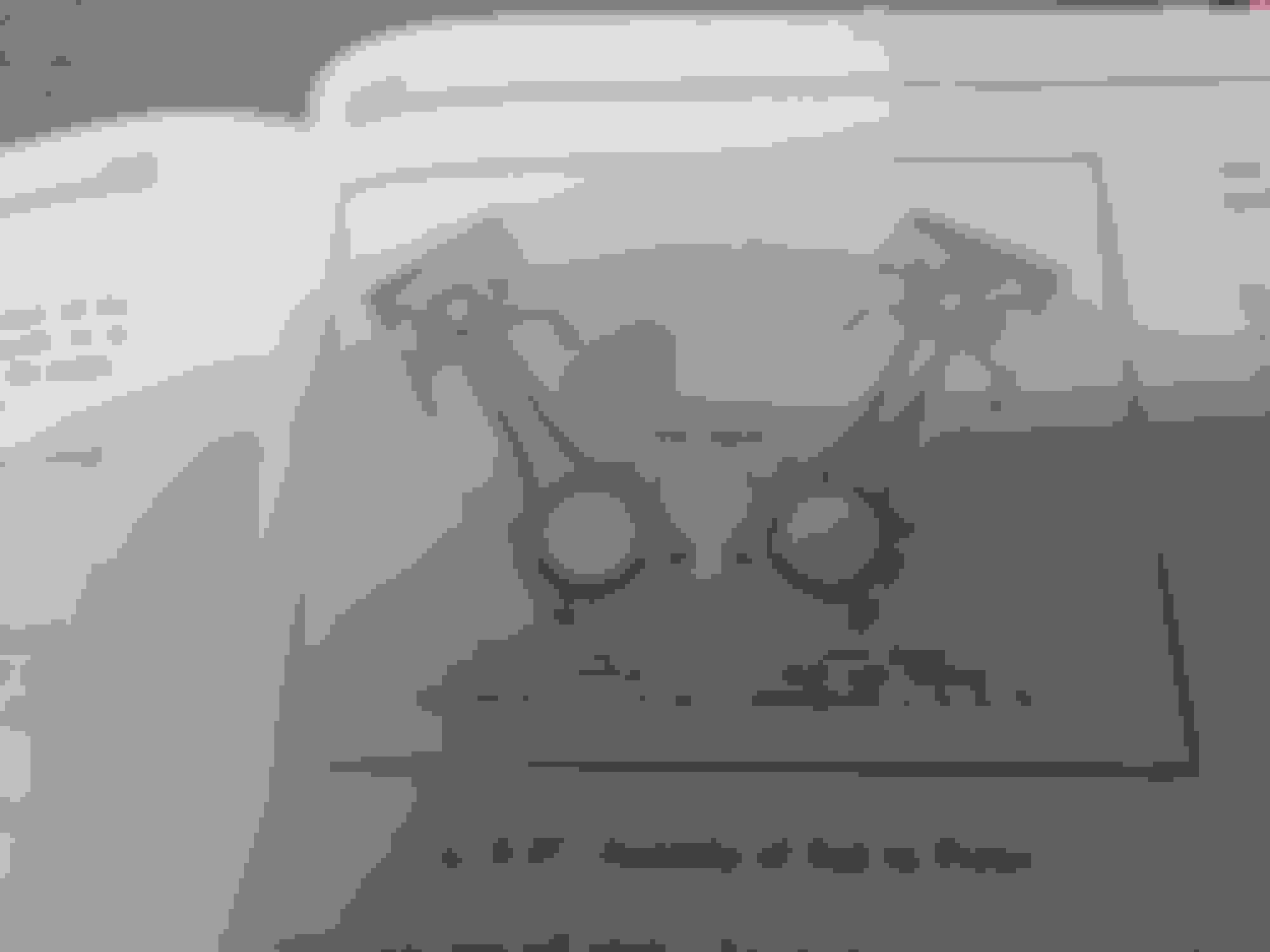
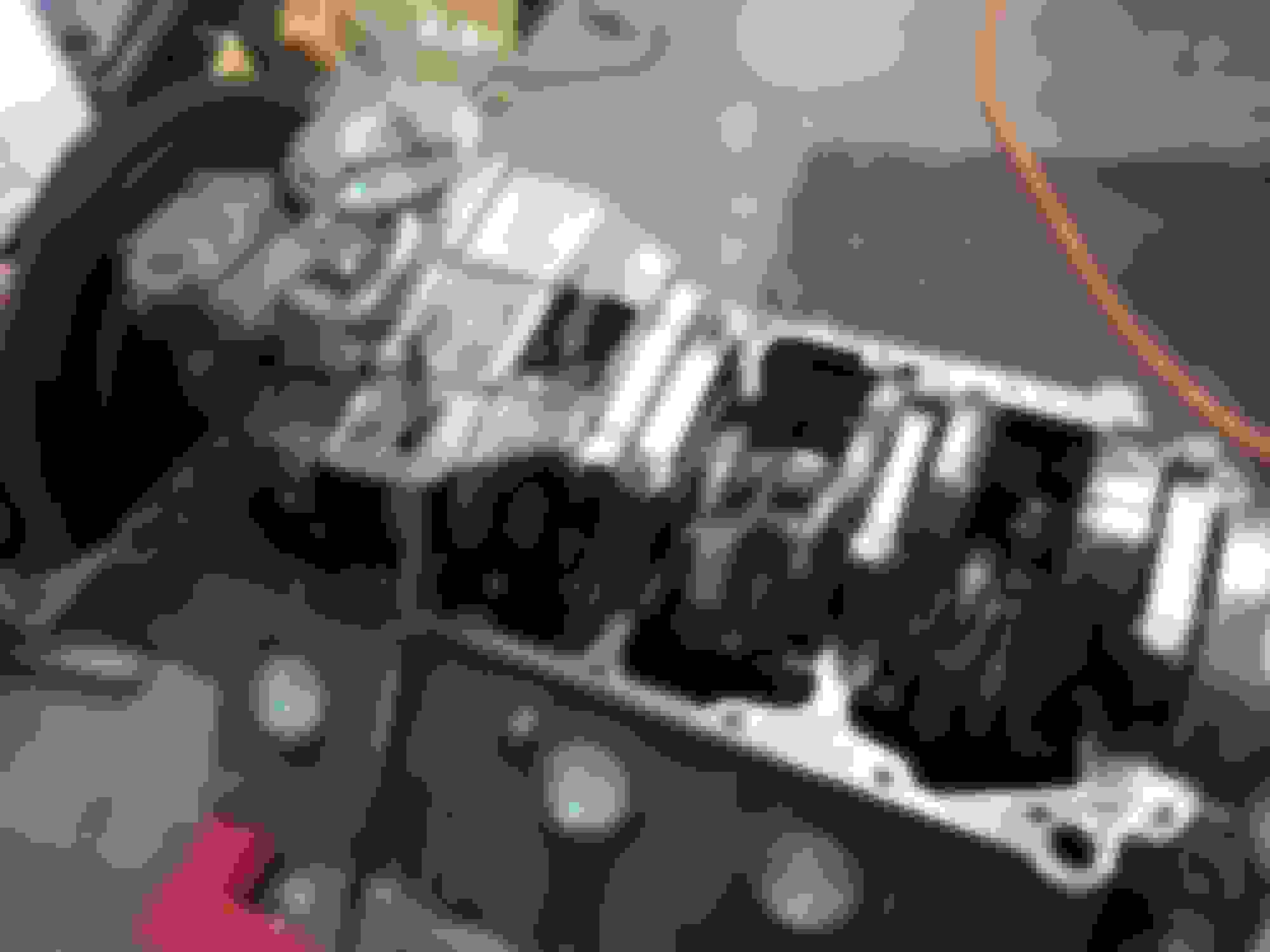
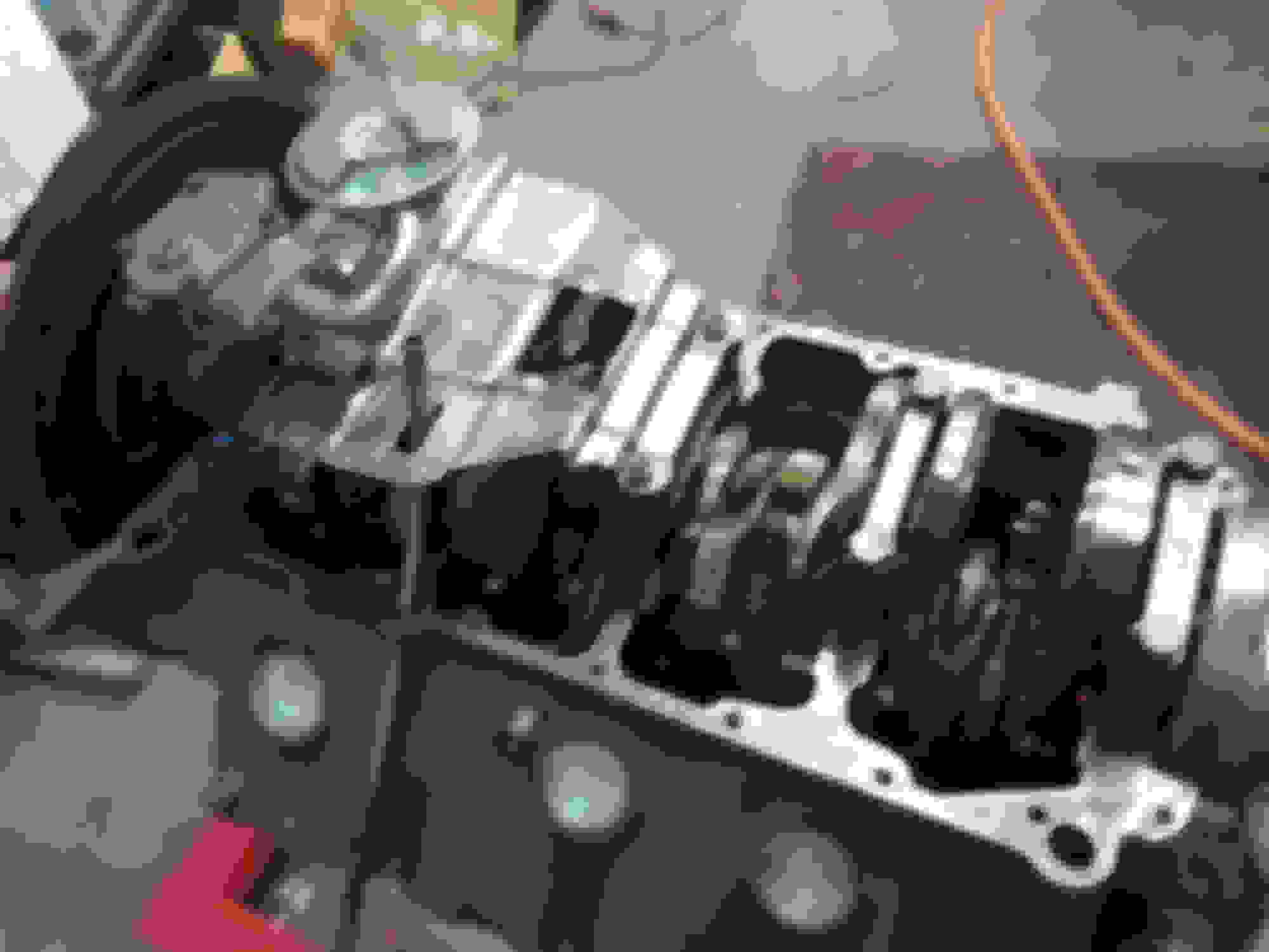
I next installed the rest of the pistons and rods . Of note , on these engines is the orientation of the rods and pistons .
My forged pistons were non directional , but stock cast pistons will have either a letter "F" or a notch . This must always be toward the front .
In addition, the rods must be oriented so that the "spit hole " is aimed toward the center of the engine . When this hole aligns with the crank journal oil hole , it spurts a shot of oil toward the camshaft . Aiding lubrication of the cam .
Also of note are the rod bearings . They should have a notch in the bearing where the "spit hole " is .
The set of Sealed Power bearings I got didn't . I got a set of old stock bearings with the notch , but they were so "shelf worn" that I could only use half of them . That's just what I did , I used them in the rods , and used the Sealed Power bearings in the caps .
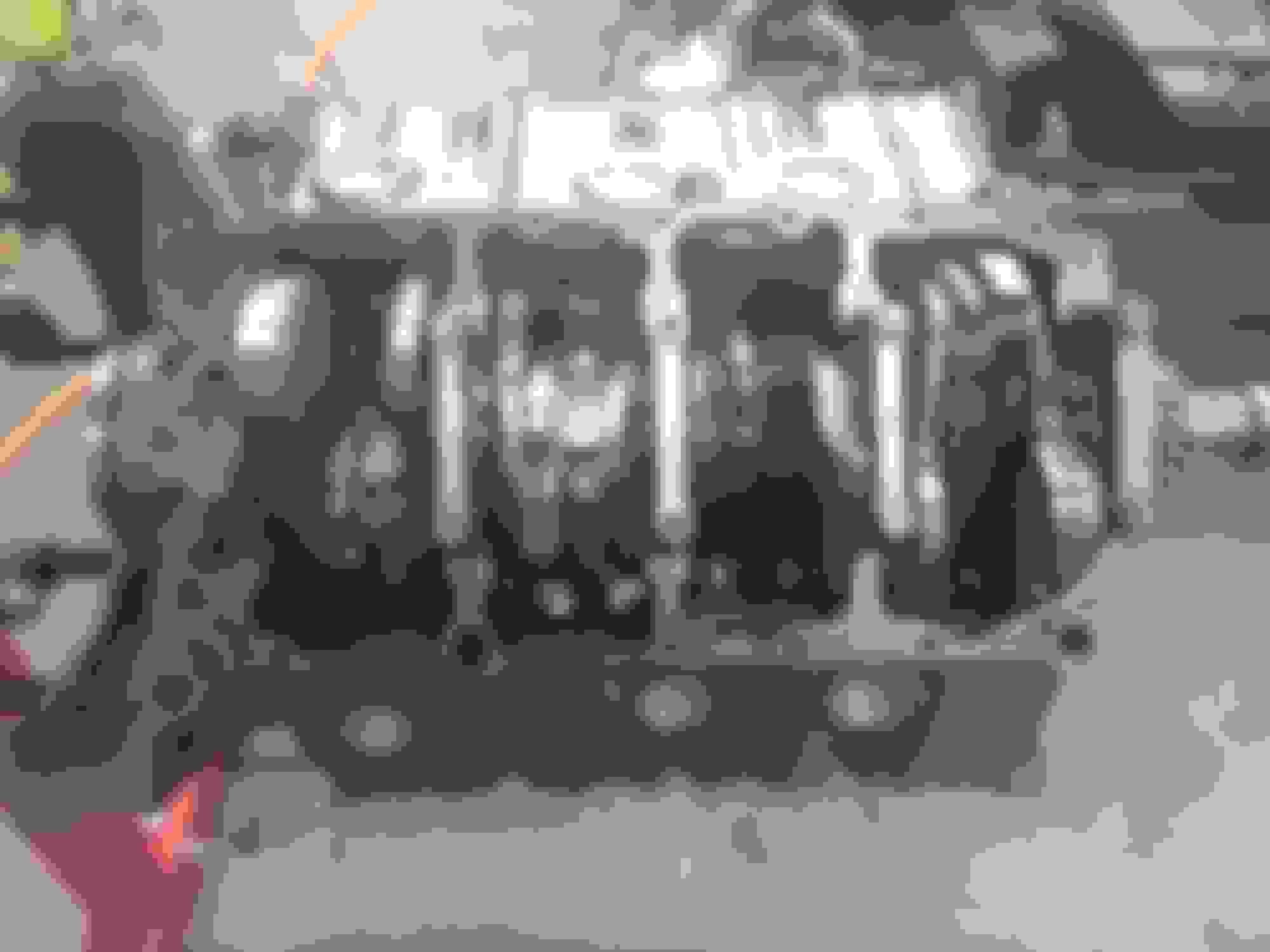
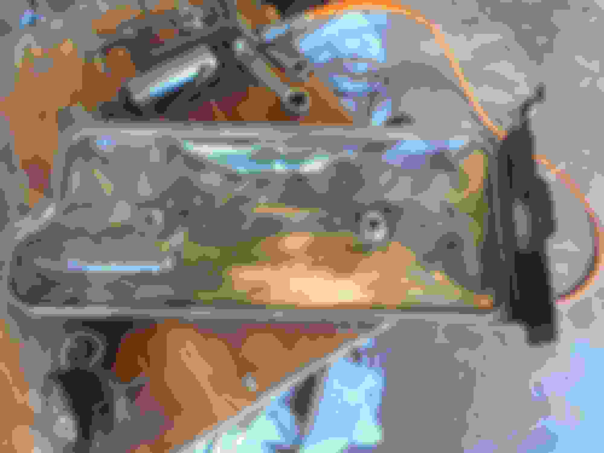
Then the clearance between the rods was checked with a feeler guage .
This is what it looked like all together ;
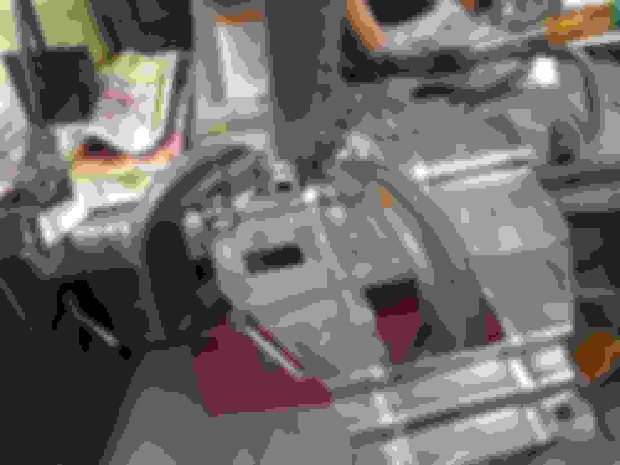
I then turned the crankshaft with an old " bending beam " torque wrench .
It took about 20 ft/lbs to turn it over .
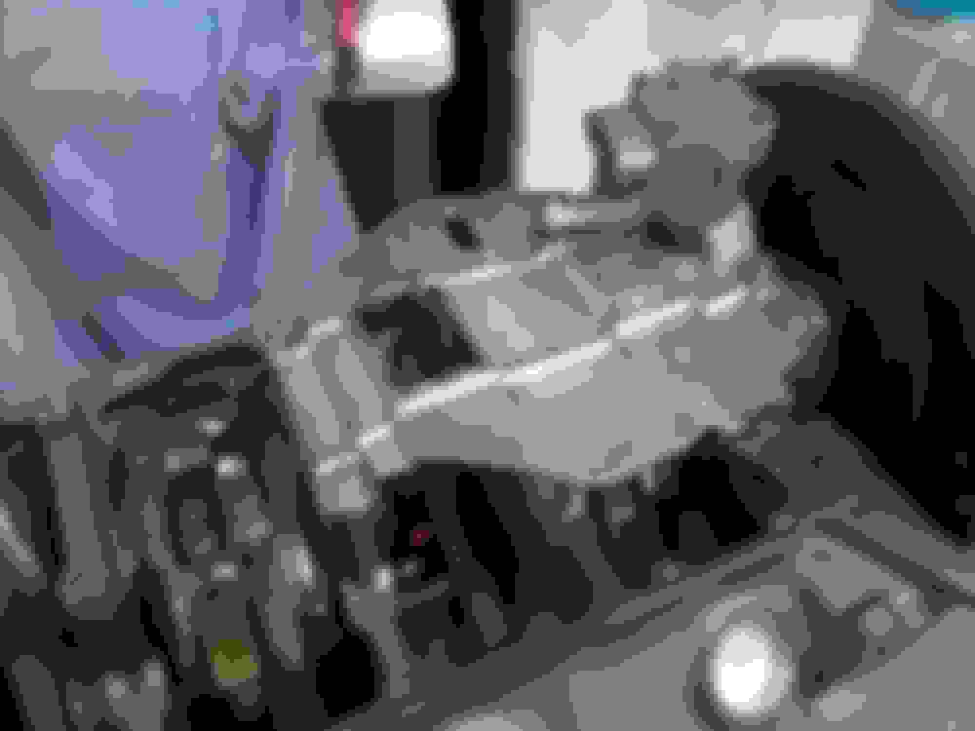
Next the flywheel was installed . I'm using a stock '63 Olds stick shift flywheel .
I needed bolts , and I discovered that Ford 351 flywheel bolts are the same .
I got a set of ARP 's from Jeg's .
I love this build. Hardly anyone messes with the Gen 1 Olds V8 anymore, at least you plan on exploiting one of their strength's, a multiple carb intake. Should really move all that steel down the road.
Hehe, that was my point to but I'm thinking the other way. I think 20# is a lot. I know my rings probably have less tension than yours but mine was considerably less.
Location: north of Toronto and quite a bit West!!!
Posts: 514
Air Engine!!
Originally Posted by Charlie Jones
Sure does , car was sold new in Alamogordo , New Mexico .
You said at the beginning your car didn't come with an Engine but I noticed an Air Harmonic Balancer. Do you have all the other necessary parts to install on your new engine to have your Compressor and Thermatic fan all function together. There is a Carb that is specific if using it on an Air Engine. I've just gone through this maze of not having all the parts needed and had to track them down afterwards. Just askin'.
You said at the beginning your car didn't come with an Engine but I noticed an Air Harmonic Balancer. Do you have all the other necessary parts to install on your new engine to have your Compressor and Thermatic fan all function together. There is a Carb that is specific if using it on an Air Engine. I've just gone through this maze of not having all the parts needed and had to track them down afterwards. Just askin'.
The engine I got , fortunately , was also from an A/C car . I think I have everything to hook it up and make it work .
Time to update again .
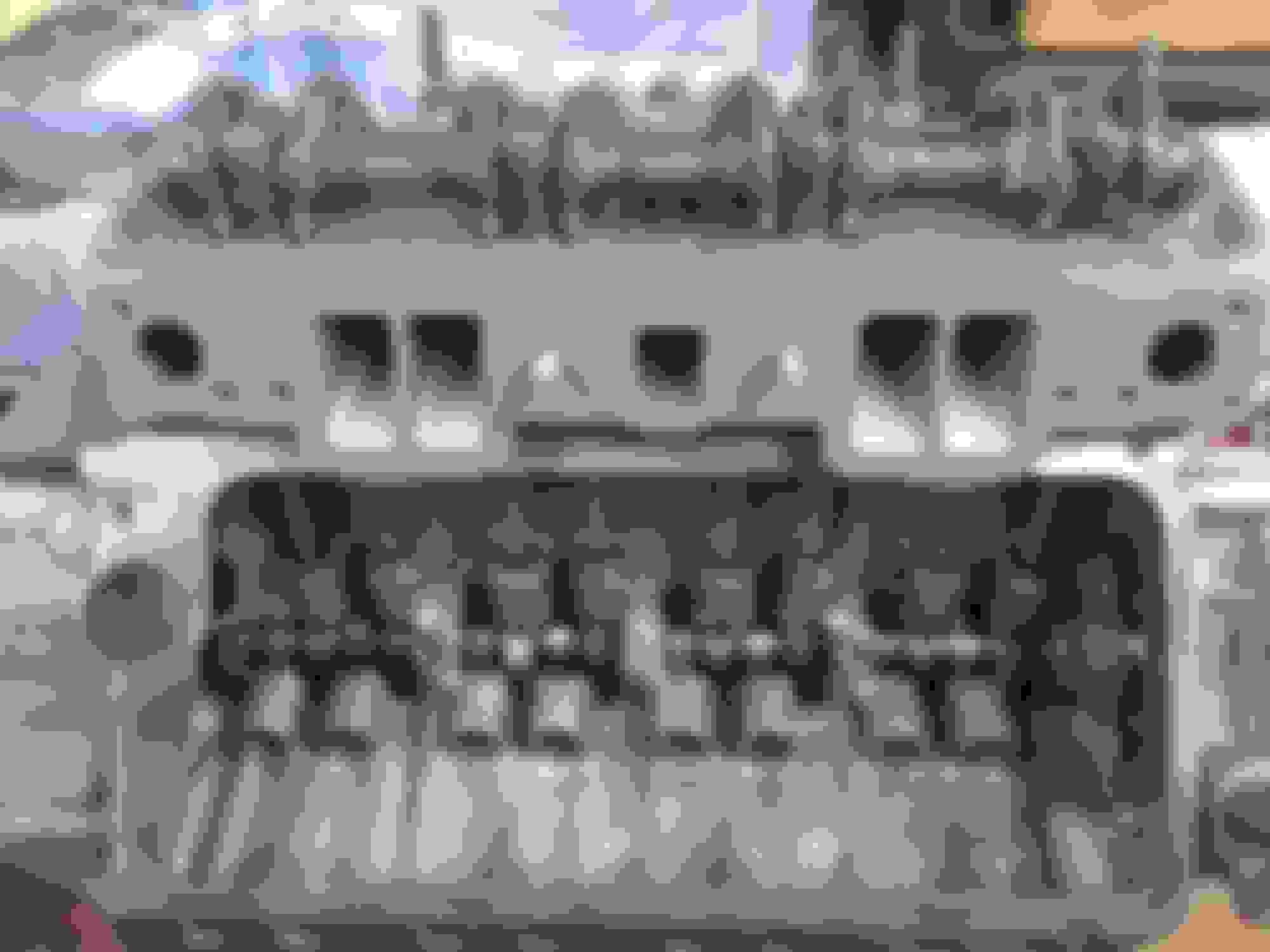
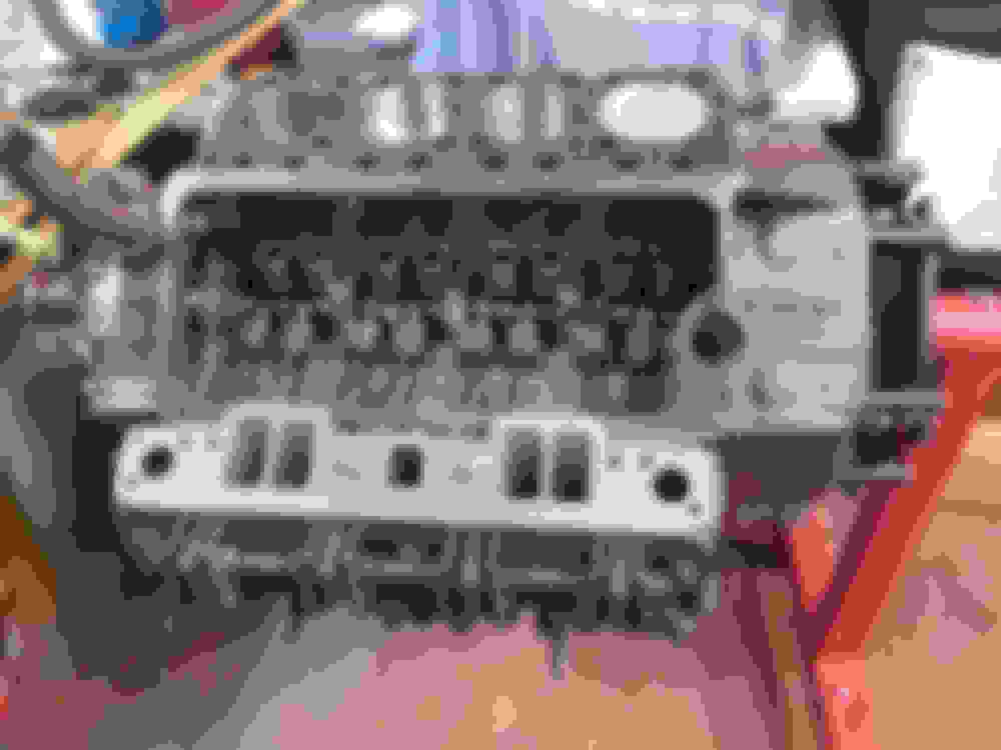
There is an oil passage in the heads which supplies oil to the rocker shafts .
Make sure it's clean .
The rocker arm assemblies were next.
I found 16 NOS rockers and shafts . The arms and stands all slide off the shaft , except one stand (per side ) . This stand is retained by a pin , that can be removed by a drift punch thru a hole in the bottom side .
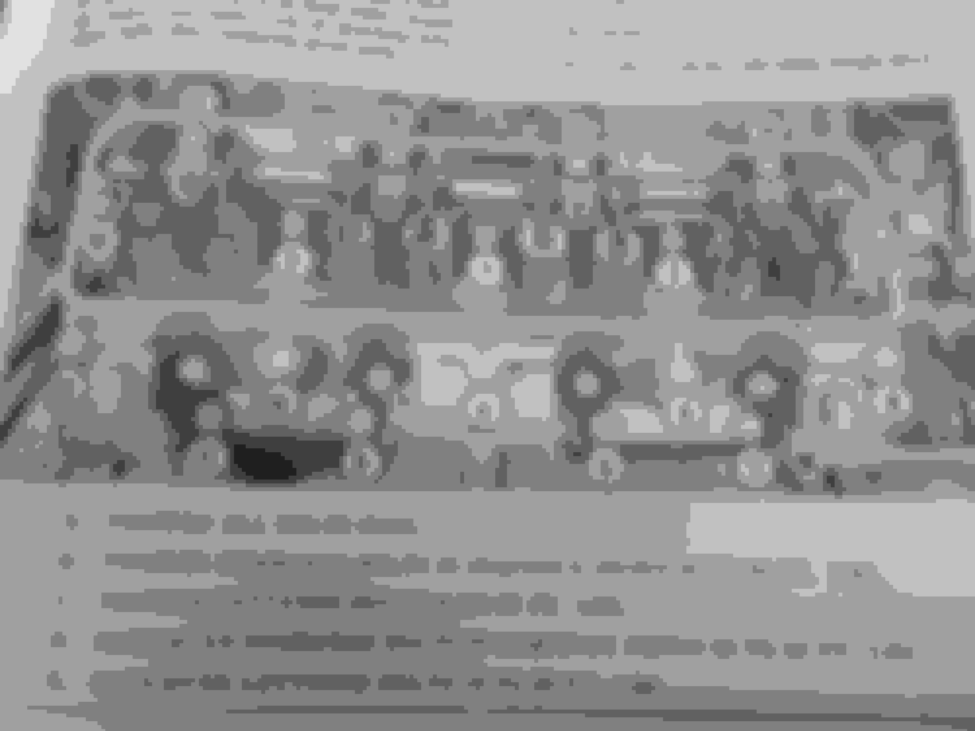
Next the heads and rockers were put on the block and torqued according the chart .
Then the other head was installed ;
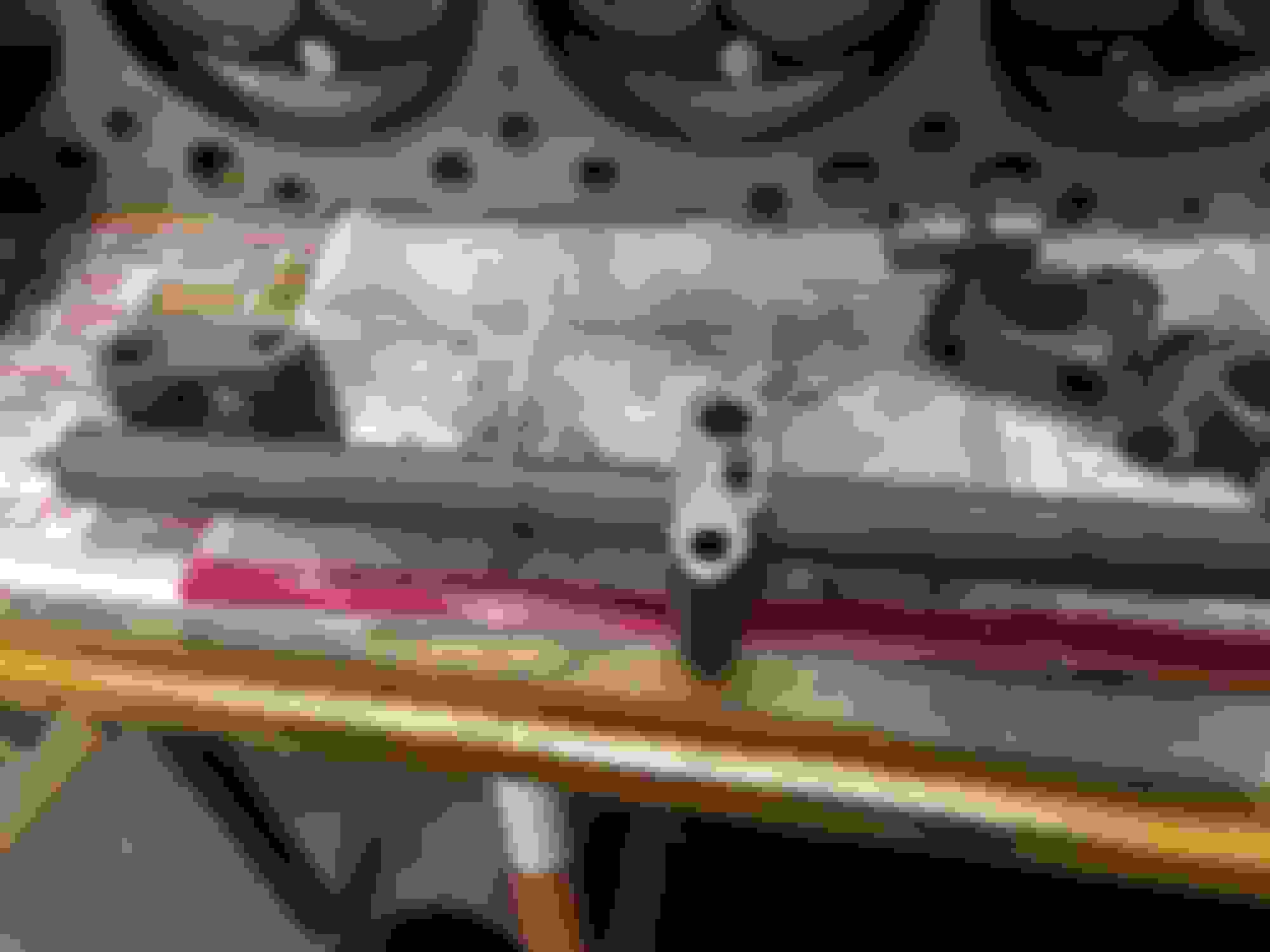
Here's a little trick I found to tell if the valve stems are too long or short .
After the valve gear is installed and the heads have been properly torqued .
Bar the engine over until #1 is in the firing position .
Twirl the pushrods between your thumb and forefinger . The rod should twirl very easily , but not have any "play" up and down.
Turn the crankshaft one quarter turn and check the next cylinder in the firing order . Repeat .
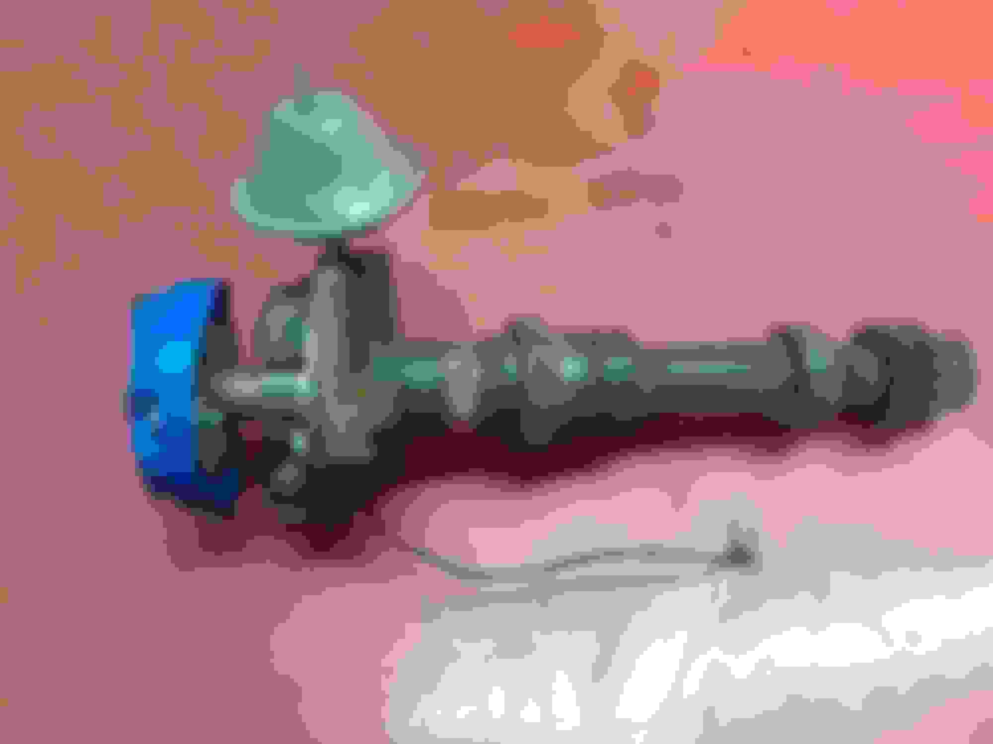
This well worn distributor is going to Everyday Performance in Granby , CT for a rebuild and re-curve .
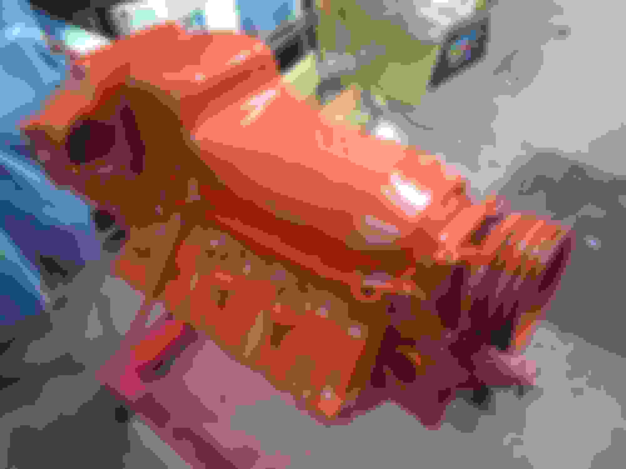
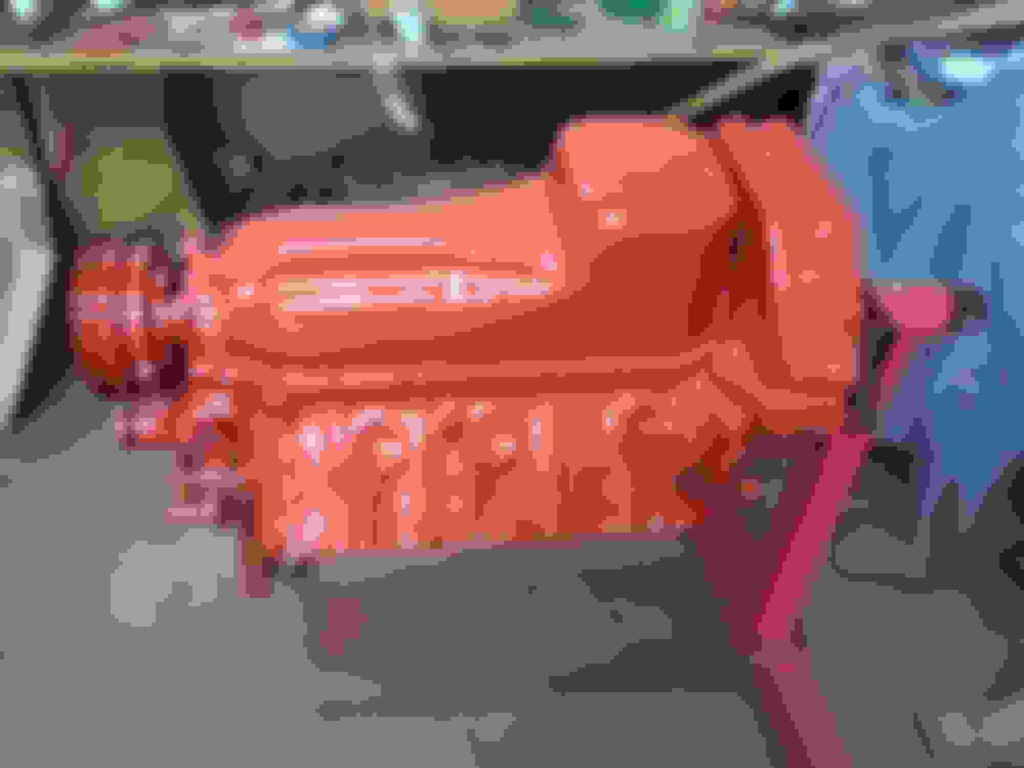
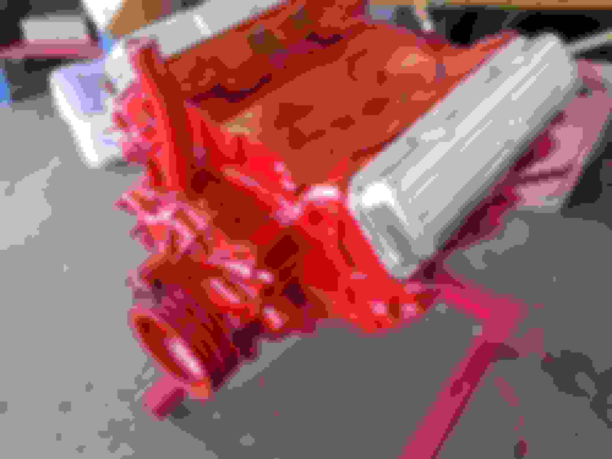
It's starting to look like an engine now . I poured assembly lube on the cam one more time , before installing the valley cover .
Then the top end was masked and painted .
My intent is to have the rocker covers chromed . But , in the meantime , just to see what it will look like , I painted te covers with some "chrome " paint from Ace Hardware .
I just started to do this and I noticed that the engine block had plugs in some of the water passages and I noticed you did not replace them on yours. Did your machine shop say they weren't necessary? I looked at my shop manual and it shows how the water flows and they don't show water going threw the plugged areas. Just curious.
Thanks
No they were all replaced . probably after the picture was taken .
The machine shop didn't install them , as they were already removed (by me) . And they weren't certain where they went . I did install six plugs under each head .
No they were all replaced . probably after the picture was taken .
The machine shop didn't install them , as they were already removed (by me) . And they weren't certain where they went . I did install six plugs under each head .
I wonder when they started to use a windage tray? They didn't have them on 61 or 62. Must of been 63 when they changed the oil pan. Still trying to figure out exactly what the difference is in the low compression and high compression heads. I know the valves are the same because the part numbers are the same and ports look the same side by side. Learning a lot here
Last edited by KQQLCAT; April 30th, 2018 at 06:11 AM.
I wonder when they started to use a windage tray? They didn't have them on 61 or 62. Must of been 63 when the changed the oil pan. Still trying to figure out exactly what the difference is in the low compression and high compression heads. I know the valves are the same because the part numbers are the same and ports look the same side by side. Learning a lot here
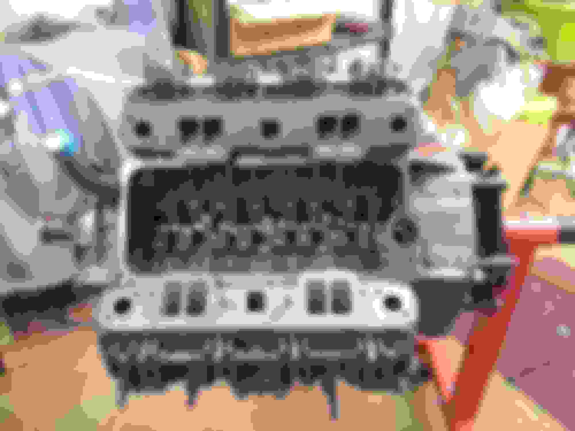
in 1961 the Starfires got a special head with larger valves (#23)
All the rest got #20 heads . From 62 thru 64 all 394s got #23 heads .
The compression differences were made by the "dish" in the piston .
I am in the process of building my 1949 olds coupe with a 1962 394. If you want to run a roller cam without sleeving your lifter bores you can do what I did. There are no .921 hydraulic roller lifters with cross bar on the market. I got 6.2 or 6.5 GM diesel roller lifters and dog bones,with some machine work they look like they are going to work fine.
I am in the process of building my 1949 olds coupe with a 1962 394. If you want to run a roller cam without sleeving your lifter bores you can do what I did. There are no .921 hydraulic roller lifters with cross bar on the market. I got 6.2 or 6.5 GM diesel roller lifters and dog bones,with some machine work they look like they are going to work fine.
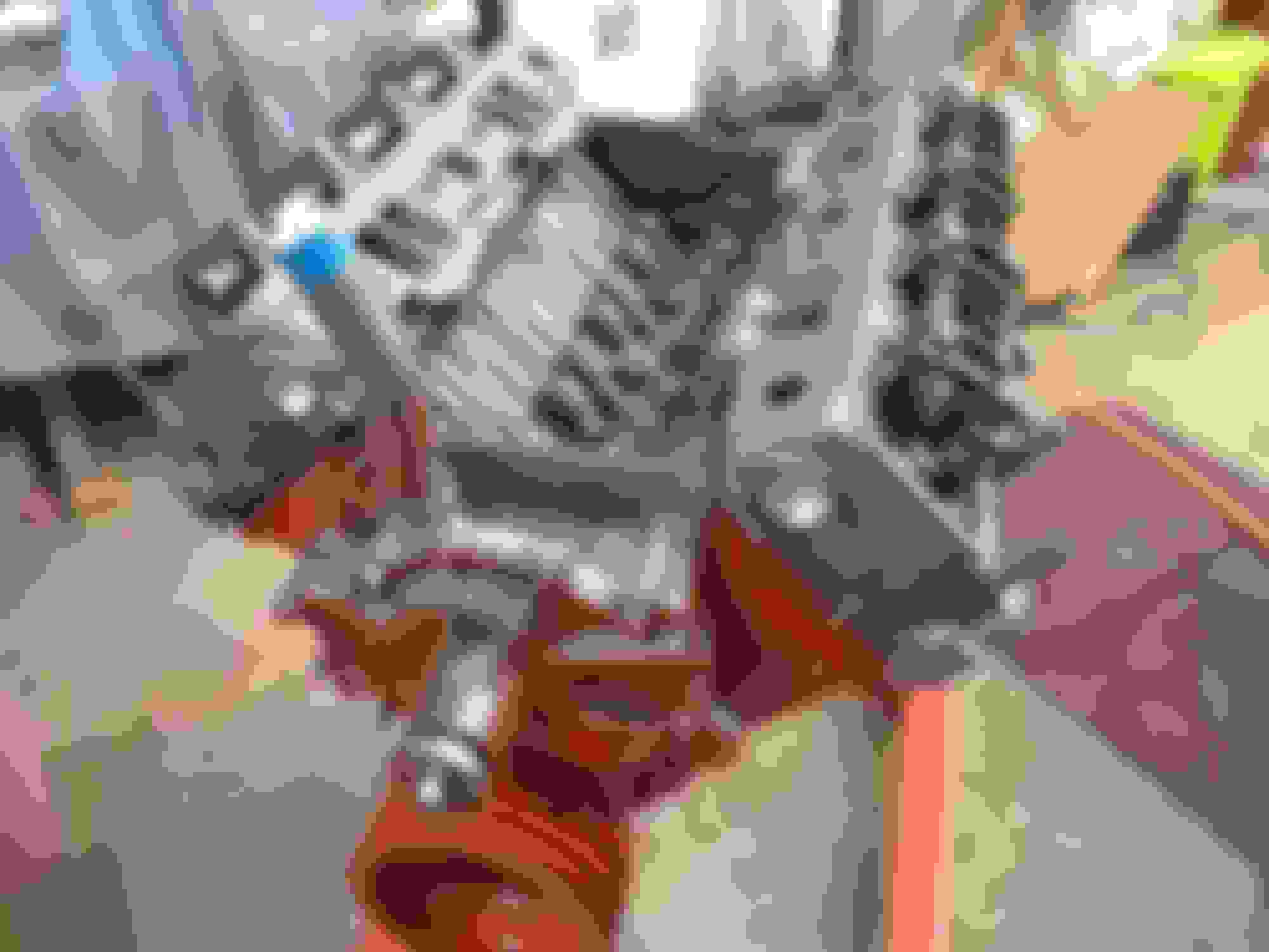
If you can find the dog bones out of a 350 gm diesel with a roller cam you only have to drill a hole in the center I could only find two of them. I got the dog bones on ebay out of a 6.2 gm diesel the problem is the lifters come out of the bore about .100 so you have to counter bore the back side of the dog bone so the lifter will clear. Then I made a plate to go on the bottom of the lifter bores to hold the dog bones down. That doesn't have to be tight you want the dog bones to be a little sloppy. You can see that in the pic. let me know if you need any more info. I have a lot of pic.
If you can find the dog bones out of a 350 gm diesel with a roller cam you only have to drill a hole in the center I could only find two of them. I got the dog bones on ebay out of a 6.2 gm diesel the problem is the lifters come out of the bore about .100 so you have to counter bore the back side of the dog bone so the lifter will clear. Then I made a plate to go on the bottom of the lifter bores to hold the dog bones down. That doesn't have to be tight you want the dog bones to be a little sloppy. You can see that in the pic. let me know if you need any more info. I have a lot of pic.
Thanks, nice job. I might try something similar on a '57 371.
I know it's just an engine but I could look at them forever. Sorta like the car show yesterday. Everything from a 1917 LaFrance fire engine to some more modern stuff.

 March 25th, 2018, 08:13 PM