When you click on links to various merchants on this site and make a purchase, this can result in this site earning a commission. Affiliate programs and affiliations include, but are not limited to, the eBay Partner Network.
I have a 1966 Starfire with, what I am being told, a "standard" 1966 Toronado steering wheel. I HATE it. I just don't like how it looks, especially after I saw pics of the other B-body steering wheel for this year. I have been told that this particular steering wheel (Toronado) was used in 1966 for any B-body with the tilt/telescopic option which my car does have.
1. Does anyone have any knowledge about this?
2. Can I install a standard SW on my tilt/tele column?
3. If so, were 65/66 SW the same on big cars?
Funny you should ask...just gota do a search here.
Not 100% sure it applies to your situation but other GM wheels of the era might interchange. Sounds like you have to verify spline count and adaptor dimensions to verify the tilt vs non tilt.....JOE!
A 1963-67, C2 and 1968 C3 (Corvette) wheel and adaptor could work. Ecklers, Mid America, Corvette Central and others... For Olds, Fusick, Year One, OPGI etc...plenty of reproduction stuff out there. Buy and test fit. Send it back if it doesn't fit.
In other words, open up your search to other GM brands.
Have you looked at Ididit and Flaming River for a whole new columns? These guys will know what wheel fits and what won't. Both have tech depts. Sell your tilt to cover the cost.
I've had a couple of 66 big cars for 20 years or so, here's what I know about Big Olds tilt and telescoping steering columns. Since I was a kid I thought the 4 spoke wheels looked like an airplane yoke. Cool.
To get one, keep an eye on Ebay with a custom search something like "(66, 1966) (Olds, Oldsmobile, Caddy, Cadillac) steering column -billet -cutlass -442". You might be able to mix and match, but best option is probably a good original.
In '65, Olds offered a tilt column only, no telescoping. In '66 the tilt & tele debuted for the Olds big cars. My Dad bought one for his (now my) 98 convertible. When I got my '66 console-shifted Starfire, it had the standard wheel you refer to, but I had a hoarded tilt & tele that I swapped in. Nice upgrade. The difference between the column & console shift columns was that the top ring of the column (beneath the wheel ring) was Starfire-specific: it had no right hand hole for a column shifter like normal 88's and 98's used. I may have swapped the standard wheel column ring onto the tilt & tele column and painted it. But maybe the standard wheel column is smaller diameter, I can't quite remember from 1998 when I rebuilt it.
The '66 Toronado also offered the tilt & tele column as an option, but some parts are a bit different from the B & C cars. First, the 4 spoke wheel is deeper on the Toro's as compared to 88/98's. It also has a different center piece. The Toro column lower shaft which connects to the rag joint is also different from the 88's and 98's. If I recall, it's a bit longer. Most of the mechanical pieces inside the upper column will swap from the Toro to the 88's/98's, but you can't put a whole Toro column into a 98 (I tried). However the horn ring, turn signal switches (mechanical & electrical) and stuff like that will swap. I think the Toro bowden cable is different length too (shorter?). Note also that Toro signal levers and tilt levers are black, not chrome like 88's/98's/Starfires, but that's aesthetics - they'll work and not look out of place.
I believe Olds changed the columns substantially in '67 when they went to a different dash design and different electrical connections, but maybe not. I'm pretty sure Olds shared internal parts with Cadillacs from '65 and '66 except for the trim which is Caddy specific. So if your turn signal doesn't work, check caddy parts too.
Today these columns run the gamut on pricing, but to me it'd be worth in the neighborhood of $300 or $350 in good shape with at least a driver quality wheel. You may have to be patient. These are great columns in terms of quality, well built except for the overly-complex turn signal. The turn signal system is actually 2 switches connected by a bowden cable through the column. The top switch are some (now) fairly old plastic parts. After 53 years, the upper switch plastic parts are brittle and don't take well to much pressure. I'm not sure if this switch is GM-common enough to be available under another brand like Buick, Caddy, Chevy or Pontiac -- anyone know?
Here's an upper turn signal switch for a Cadillac that looks nearly identical to the 66 Olds 88 one I have on my workbench, but I'll bet that black ground wire is the wrong length for swapping. Caddy turn signal switch which may swap into your 66 big Olds. Very close to what's inside the big olds column. The plastic can break easily after 50 years service.
The electrical switch that actually sends power to the turn signal lights is a delco unit. Inside the switch are some small triangular brass contacts which wear down over 50 years. Wear can lead to drivers hitting the upper plastic switch harder to get a contact, which can lead to failure of the upper plastic parts and/or failure to make electrical contact. You can disassemble and clean the lower switch but by opening it, the pot metal retainers can snap giving you the problem of how to keep the restored switch back together. Here's a replacement from Classic Industries listed as an Impala switch: Impala tilt & tele switch that _may_ work in 66 big oldsmobiles. If you get one from Chevy, Caddy or other GM stay as close to 66 as you can.
If you get a column and decide to open it, a standard steering wheel puller will be necessary. Trim comes off first, then the wheel, but then you hit the horn ring which is retained by a C clamp and held fast by one of the strongest springs I know. Getting a brass & plastic horn ring off without damaging it is hard. Or at least I have 3 in my collection saying I'm no good at it. Beneath the horn ring and the megaspring is the upper turn signal. To remove the turn signal, first disconnect the lower bowden cable connection to the electrical switch. Then you just need 3 screws and it's out, but be careful not to hang the bowden cable up inside the column. These things are easiest to work on out of the car.
Unless something is obviously broken, most of what these things need is a good cleaning. The brass electrical contacts wear down over the years plus get gummed up with dust, grease, & crap. I lightly dremel-grinded my wheel horn contacts last night to clean them up and get a good connection.
I'm not looking forward to my battle with the horn ring retainer, but soon I'll get round to it. My Starfire horn only works in some clock positions, so I know I have to open it up at some point. Just waiting for the right 5 or 6 hour stretch to get into it.
Hope this helps. The turn signal switch on my 98 has been a bit tricky for years. But my Starfire is good as the day it was installed. Except for the horn ;(
How to make a Tilt & Telescoping Horn Ring Spring tool
For anyone following this, recall that yesterday I was dreading opening up my 1966 Big Olds tilt & telescoping steering column to fix the horn, chiefly because I have bad memories of wrestling with the horn ring spring in years past.
Turns out, I hated the job so much that somewhere along the way I made a tool that I forgot about. I rediscovered the tool today - happy like finding a $20 bill in your clean jeans. So I thought it might help you all if I shared what it is.
The job this solves is removing a 1966 big car tilt & telescoping steering column horn ring C clip. The clip holds the horn ring in place just below a removed steering wheel and just above the turn signal. The horn ring is retained against a very strong spring by the clip and is hard to get in & out.
Unless you have a homemade spring compressor like this: Works o.k. in place of Olds tool J22191 in the 1966 Olds Chassis Service Manual page 9-77, which I'd have no idea where to find.
The tool is just a piece of 5/16's threaded rod and some 1 3/8's (inner diameter) PVC. The PVC is notched here like the Olds Chassis Service manual tool to allow access to the C clip itself. The notch in the lower right of the PVC should be facing the other way. Sorry. It's correct below, although the notch is hidden.
First assemble the parts on the rod as you see here: Double Nut > tightening nut > washer > big washer > centering guide shims > PVC with notch at the bottom
To use it thread the rod into the telescoping shaft like the Olds telescoping retaining screw does. Once the rod is all the way in, work the 2 nuts on the end against each other (like in an e-brake line) so you can tighten your rod to lock the telescoping shaft in place. Otherwise the telescoping shaft moves in/out and you'll never get purchase on the clip you're trying to remove. Next orient the PVC notch so that you can press down on the upper edge of the horn ring while leaving the C clip exposed. You want the PVC pretty well centered on the horn ring. Next slowly tighten the long tightening nut to expose the C clip. You may have to hold the PVC centered with one hand and tighten with the other. Once you get the spring compressed enough, the clip will loosen. On mine the clip just slipped out, otherwise you can use a really small screwdriver to nudge it out once the spring pressure is removed.
When the C clip comes out, remove the homemade tool by loosening the tightener nut to release spring pressure, then remove the tool from the shaft using the double nut. Set the tool and parts aside somewhere safe.
Once you're this far in, you might as well clean and polish all the electrical connections and have a look at your turn signal switch. My brass parts had gotten a bit gummed up over the years and were hurting my horn connection.
With the horn ring off, you can get at the turn signal switch as noted above in this thread. Once you've done all you'd like inside the column, we can get to reassembly.
To reassemble, clean and grease the top of the telescoping shaft. The plastic horn ring slips over the telescoping shaft. A little lubrication makes reassembly much easier. Next note the clock position of the ends of the C clip slots on either side of the the telescoping shaft. You'll want to know where these are to orient the horn ring so that the C clip can be slipped back in into it where it came from. To get the orientation, slip the horn ring on _without_ the spring, mark the slot ends with a sharpie on the top of the horn ring plastic and outer rim of the column. Remove the horn ring after marking orientation, then slip the spring on and the horn ring above it.
Now go get the tool again, thread it into the telescoping shaft with the double nut. Line up the PVC notch so that you can slip the C clip back where it came from. This is a little fiddly, since the PVC compresses a bit. I had to slip the C clip just a little under the PVC notch, then tighten slowly. Once it lines up with the shaft slots, tap the C clip in place. Once the clip is in place, you're done.
Hope this helps some of you. I no longer worry about getting deep into this fairly complex column. With that said it took me most of morning - probably 3 hours of removal, cleaning, restoring and reassembly. But at least my horn works better!
Now I just have to get my 98 back and get at its fiddly turn signal switch.
Here's a replacement from Classic Industries listed as an Impala switch: Impala tilt & tele switch that _may_ work in 66 big oldsmobiles. If you get one from Chevy, Caddy or other GM stay as close to 66 as you can.
That switch is factory # 1993624 . It will not fit a full size Oldsmobile . It will fit '64 thru '66 F-85 / Cutlass .
The switch that fits '63 thru '66 full size Oldsmobiles with tilt is factory # 1993597 . It also fits similar Pontiacs .
Last edited by Charlie Jones; September 13th, 2019 at 09:10 PM.
I got a few interior shots the other night. Here's the tilt & tele wheel in black for 1966 in case anyone doesn't know what to look for: 1966 Oldsmobile 88/98/Starfire tilt & telescoping steering wheel
Update on the 66 tilt & tele horn ring spring compressor tool. Here are some more details which may help you build & use one if you need to service the complex turn signal switch, or your horn. The turn signal switch is below the horn ring, so you have to remove the ring to fix a bad turn signal switch.
First here's the spring that needs to be compressed on the '66 Tilt & Tele column to get at the turn signal switch or other parts of the column. It's strong, so you need a tool. Use a homebrew tool to compress this spring to service 66 Olds tilt & tele columns
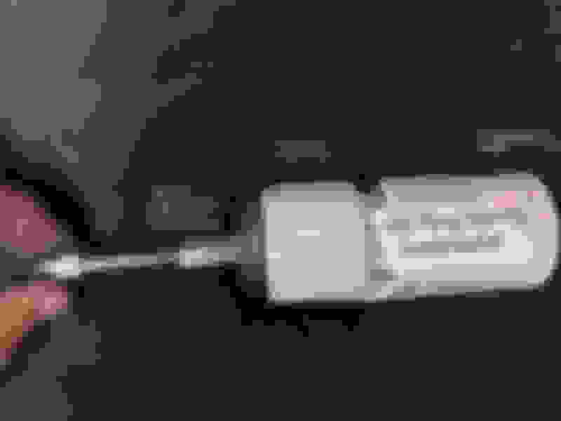
Here are the parts. These should be readily available at your local hardware store. Replacement for Kent Moore tool J221291
At the bottom of the 1 3/8" inner diameter plastic pipe, cut a notch about 180 degrees across the PVC pipe and about 1/8" deep. I used a dremel to notch it. Pipe notch allows access to the C clip that retains the horn ring on the strong spring
Here's the notch as viewed from above:
Notch the pipe so that remaning 1/2 circle will push down on the upper part of the horn ring, leaving access to the C clip with a small screwdriver or wedge.
Once the tool is threaded into the center of the telescoping arm, use the double nut to lock the shaft in its lowest position. Then you slip the plastic washers inside the PVC pipe and seat the metal washers on the top of the pipe. Then use the long nut to screw the washers and pipe down onto the horn ring to compress the PVC and horn ring against the spring. Once the C clip is loose in its channel, wedge a screwdriver in there to pop it out.
Sorry if some of this is redundant to the post above, I had a request from a member about more details on the tool. Yesterday I dug it out from my crawl space since my horn was having trouble.
So I took apart a malfunctioning '66 Tilt & tele turn signal switch the other day to clean and lubricate it and maybe get it to work better. You can buy them new with part number # 1993597 . (Thanks Charlie Jones!). '65 - 66 + maybe later big car tilt & tele switch.
I bought one for one of my cars and it works just perfectly. The other has turning lights and the switches are different. If you can get new, I recommend it. There is 50 years of usage wear in these switches that grinds down the brass contacts each time you hit the turn signal switch.
The good news is if you have a weird switch, like the turning lights one, you can harvest the brass contacts from the switch above and repair it.
Harvest these contacts from new turn signal switches for your own purposes: GM used these brass contacts in several switches in the Mid-60's. Buy new turns signals switches to collect more.
The really big news is if you have the switch pitch / kickdown switch for the 65-66 or so throttle, you should be able to redeploy (o.k., cannibalize) a new switch for something that will never be reproduced.
I thought some of you might be interested on how to open these switches and what you find inside. When you take it off the tilt & tele column it looks like this: To open the switch, bend the 3 metal retention "ears". Don't be surprised if they break. My break rate on these is easily 50%. Not really meant to be opened.
Once you've removed the spring and bent the ears outward enought to allow the bakelite to drop free, you'll be greeted by a mess of 4 ball bearings, 5 springs and 3 or 5 brass electrical contacts. I work on a clean sheet of paper towel so I can find all the small parts that want to hide.
Typical GM mid-60's turn signal switch. Repair or harvest parts as you like.
You may recognize the switch better from the other side, if you've pulled a steering column along the way: 65-66 Tilt & tele turn signals switch viewed from wiring connector side
Once you open the metal tabs, the parst spring free so fast, the trick is figuring out how they go back together. Basically it's a bakelite sandwich. Here's the order: Metal switch retainer - 4 ball bearings - middle bakelite (4 bearing grooves on the back, spring & contact seats on the front) - outer bakelite with switch contact points / terminal connections
Here's the scoop:
The 4 ball bearings allow the middle bakelite part to move back & forth smoothly when you hti the turn signal The 4 ball bearings allow the switch to slide easily across the metal housing.
On the opposite side of the middle piece are the holes and slots for the contact springs & contacts, respectively. Springs are all the same size, they can be mixed & matched. There are 3 sizes of contacts which I'll detail in a moment. Here's the right way to put the springs back in: The middle piece of the bakelite sandwich that is a Mid-60's GM turn signal switch
Once you're this far it, you'll probably get how it works, but the contacts with atop the springs like this: Contacts sitting on top of springs that force them against wiring terminals
Here's a quick side by side to show how the contacts mate to the spade terminals: Hidden parts of the turn signal bakelite sandwich
If you're lucky, your metal retention clips did not break off when you gently bent them to release the bakelite. If you're unlucky, they broke like this:
Design flaw: these metal retention loops/pins don't usually survive opening for cleaning & servicing.
It wouldn't be too hard to gin up a ziptie solution to keep the bakelite in place, but why not buy new? The main point of the post is what's inside, and how you might want to cannibalize new brass contacts for other, more rare switches. If you manage to open, clean, repair & close it to working status, more power to you!
Wow Chris, great write up. Love all the photos.
I will be tackling this job soon. I'm working on a 1966 Delta 88 with turning lights. Currently the turn signal switch is being held on under the wheel with a zip ties and a rag.
My '66 Starfire horn has been flaky for the past couple of years. The horns, relay and stuff are all good, I knew I had a problem in the column.
This car has a 1966 tilt & tele wheel, which is on the complex end of steering columns of day.
Symptom/Problem
The horn would work when turning, but not work when going straight. For 2-3 years now, I've been replacing and straightening the brass horn ring which rotates with the wheel on turns & sends a signal through a spring-loaded pin to the horns. Nothing helped.
First Solution: clean & sand the horn ring
I figured the brass ring was worn down from spring-loaded pin pressure over 55 years, so I tried a few different rings which all failed, differently. I even sanded the rings flat so that the mating surface was consistent & not grooved. It didn't help.
Second Solution: clean the spring loaded horn pin
Next I lightly Dremel cleaned the head of the contact spring, just in case it was too dirty to make a good electrical connection. I put the horn ring back on the column and hit it with a test light connected to ground. At each of the 3 mounting tabs, once I grounded it, I got a horn sound. Great, then I could rule out stuff below the ring since it was making enough contact from the 3 mounting tabs to blow the horn.
Third solution: trouble shoot the Steering wheel switches
So now I isolated the problem to somewhere between the horn switches on the steering wheel and the horn ring tabs buried in the column. Since the wheel was off, it was easy to test on the bench with a continuity tester. What I found was several loose screws. So I tightened those, just a bit - several bite into very soft conductive brass, so there's no point in over-torquing. In particular, the wheel horn switches are connected via screws to an upper brass ring which transmits the ground path down to the horn ring.
The big deal was that the spring that allows the telescoping feature in the column had gone soft. That spring also carries the electrical connection between the steering wheel & the horn ring. I have a few spares so I compared the one in use to my spares and found it had become compressed over the years. This compression led to an inconsistent connection between the steering wheel switches and the horn ring. I replaced the spring with a longer one (i.e. less compressed from use) and was back in business.
Grounds are a big deal
Along the way, I found I'd painted over some connection points that should have been left conductive. I cleaned the paint off and sanded to metal. I also found a few loose screws that were inhibiting the steering wheel signal. The great thing is the way these switches work - ground the switch on the wheel with a press and you get a horn sound. No software, no lines of code, no AI, just ground-for-sound.
I love the simplicity. A real antidote to today's world of surveillance capital.
Upshot
The lack of horn presented as a horn ring problem but was actually a spring between the steering wheel horn switches & the horn ring that had gone soft.
Oh - I must say that the column was not the problem. It turned out to be an inconsistent ground in the rag joint that is supposed to feed a ground to the column.
I added a grounding wire to the rag joint and it works perfectly again.

 September 11th, 2019, 08:36 AM