When you click on links to various merchants on this site and make a purchase, this can result in this site earning a commission. Affiliate programs and affiliations include, but are not limited to, the eBay Partner Network.
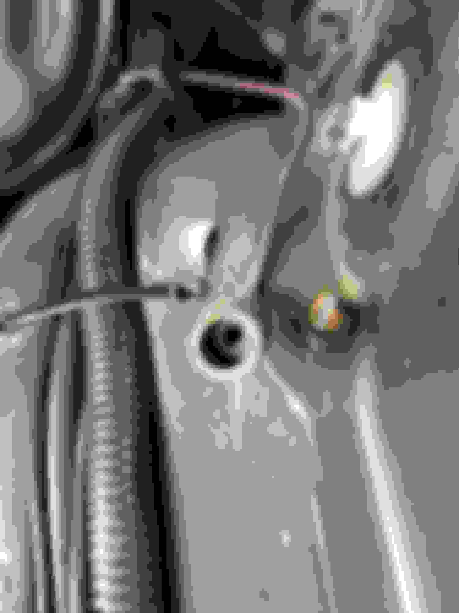
I found this when I was installing the torque braces on my 72 Supreme. It was just dangling between the firewall and inner fender liner. It runs down to the box attached to the firewall. (See second pic)
It goes to the differential pressure switch on the brake distribution block or combo valve. I'm guessing that your car was converted to discs and that was not hooked back up.
It goes to the differential pressure switch on the brake distribution block or combo valve. I'm guessing that your car was converted to discs and that was not hooked back up.
Hmmm...I'm pretty sure the front discs are original based on the fact the rotors have the "cooling grooves" on both sides. Is there any way to visually confirm this? (I don't have the build sheet)
Hmmm...I'm pretty sure the front discs are original based on the fact the rotors have the "cooling grooves" on both sides. Is there any way to visually confirm this? (I don't have the build sheet)
Either way, do I need to hook the wire back up?
I was guessing on the originality. There's no reason to disconnect that wire. The purpose is to illuminate the BRAKE light on the dash if you lose pressure in half the braking system. Of course, the light comes on right AFTER your foot goes to the floor and you say "Oh $H!T". I'm pretty sure this system was designed by Captain Hindsight.
It usually means the shuttle valve inside shifted one side or the other and you may have limited front or rear brakes. Also check if the fluid level is low.
So if I hook it up and my OH $H!T light comes on, does that mean the distribution block is bad?
It means that the internal piston has shifted one way or the other. Usually this happens when brakes are bled after major work. If you have the original cast iron prop valve, rust in the bore frequently can cause the piston to get stuck when it travels to one side or another.
As Eric stated ^^ above. In theory, if you hook it up the lamp should NOT illuminate if the combination valve is operable & engaged at its normal position.
As Eric stated ^^ above. In theory, if you hook it up the lamp should NOT illuminate if the combination valve is operable & engaged at its normal position.
Which suggests that whoever bled the brakes the last time couldn't figure out how to get the light to go out...
And, if you prefer a video on the combination valve and procedure to bleed, here is an excellent video to add to Joe’s diagram of the ‘combination valve’.
It's sometimes interesting how things come full-circle as per oldcutlass' question in Post #33 to which you referenced Post #15 and which I referenced the above link Post #13 which is the same link I referenced in Post #43 of your previous thread.
I have a theory as to why it was disconnected...a PO had set the car up for drag racing, and in an attempt at a poor man's line lock, he drained the rear chamber of the MC. When he did that, it probably threw the light, and since he didn't want the light on, he pulled the cord. Sound plausible?
I have my own theories - which thus far in this thread have not been tested:
(1) When you hook up the wire to the combination valve switch - the light will illuminate; or,
(2) When you hook up the wire to the combination valve switch - the light will NOT illuminate.
I have my own theories - which thus far in this thread have not been tested:
(1) When you hook up the wire to the combination valve switch - the light will illuminate; or,
(2) When you hook up the wire to the combination valve switch - the light will NOT illuminate.
Ground the connecter to know if the wiring and light are good. It should come on when you turn the key to run before you start the car. Once its running it goes out. This is how you know the circuit is good. If the light doesn't come you have to troubleshoot.
Last edited by Orlando 1; Apr 5, 2020 at 12:52 PM.
Ground the connecter to know if the wiring and light are good. It should come on when you turn the key to run before you start the car. Once its running it goes out. This is how you know the circuit is good. If the light doesn't come you have to troubleshoot, lives are at stake.
Ground the connecter to know if the wiring and light are good. It should come on when you turn the key to run before you start the car. Once its running it goes out. This is how you know the circuit is good. If the light doesn't come you have to troubleshoot, lives are at stake.
This is in your owner's manual.
Not true, grounding the wire will light the light as long as the key is on. What you described is the normal light test when the wire is connected.
I didn't get a chance to test the connector today, biut shooting for tomorrow. In the interim, suppose that when I do test it, the light doesn't come on..then what? Is there a fuse I could check, or can I back trace the circuit?
And...if I test it and the light does come on, then can we say that the valve is good, or do I need to work that side of the equation? Maybe the contact on the valve needs cleaned up?...
In hindsight, I should have tested the connector before I hooked it up, bit I had no reason to doubt that it was good since everything else that I've either hooked up or fixed electrically has worked...oh well, live and learn I guess.
Does the light come on when you engage the EBrake? If yes then there is power to the light. If no then its time to troubleshoot and we can cross that bridge when we get there.
Does the light come on when you engage the EBrake? If yes then there is power to the light. If no then its time to troubleshoot and we can cross that bridge when we get there.
Yessir...the light comes on when the e brake is engaged....does it share the same circuit as the distribution valve?
Does the light come on when you engage the EBrake? If yes then there is power to the light. If no then its time to troubleshoot and we can cross that bridge when we get there.
Yessir...the light comes on when the e brake is engaged....does it share the same circuit as the distribution valve?
Yes, Dave. It is identified in your CSM. The tan wire originates at the differential brake SW, passes into the Generator & Forward Lamp Dash Connector (module plug), exits as a 20 gauge tan double white striped wire then splits in two just before the wire enters the instrument cluster connector (module plug): One wire leads to the Parking & Low Brake Warning Lamp the other wire leads (independently) to the parking brake switch.
EDIT: I should modify my statement. The information I provided is from the wiring diagram of my 1971 CSM. Your wiring diagram may be dissimilar, yet similar in many regards. None-the-less, the wiring diagram is in your CSM.
Last edited by Vintage Chief; May 15, 2019 at 08:21 PM.
Well, in theory the differential brake SW is not energized when the combination valve's differential valve is in it's normal centered position - the differential brake SW plunger is EXTENDED (creating a break in the circuit). If the differential valve moves in either direction this causes the differential brake SW plunger to move up INTO the differential brake SW thereby closing the circuit and sending a signal to the brake lamp causing it to illuminate.
So, in theory, if the differential valve is in its normal centered position, if you remove (unscrew) the differential brake SW from the combination valve & insert the wire into the differential brake SW - you should be able to replicate a functioning differential brake SW by pushing the plunger into the differential brake SW thereby closing the circuit and the brake lamp should illuminate w/ the key in the ON position. Pushing the plunger in & out should cause the brake lamp to turn ON & OFF I would think.
NOTE:You could probably perform this test w/o having another differential brake SW inserted into the combination valve or at least a bleeder tool plug of the type described in the video to keep the differential valve from sliding off center when you turn the vehicle ON as long as you DO NOT apply the brakes (which may cause the differential valve to move left or right). Make sense?
Note the parking brake SW has a ground which is independent of the differential brake SW. Therefore, while they share the same circuit, engaging the parking brake SW does not validate the differential brake SW is operable because the differential brake SW has its own ground independent of the parking brake SW (based upon the CSM wiring diagram).
What if I jacked the rear up until both tires were off the ground, then started the car, put it in gear and then hit the brakes? If the rear tires stop, then I would know the rear half of the valve is working, right? In turn, check the front brakes by having someone spin the wheel and I again apply the brakes. If the wheel stops, then I would know the front half of the valve is working, right? This way, I would at least know the valve is working machanically, correct?
Dave - Why would you suspect the combination valve is not operating correctly? It's my understanding you have been driving the vehicle & the mechanical braking system is operating w/o incident i.e. your brakes are operating as designed. Brake fluid from both reservoirs of the MC is passed into the front inlet port & the rear inlet port of the combination valve. When you apply brakes, the brake pedal actuates the brake booster which in turn assists in activating the MC piston to push brake fluid under hydraulic pressure INTO the combination valve (via the inlet ports) which in turn proportions brake fluid to both the front & rear caliper pistons. If your brakes were not mechanically operating, your brakes would not be functioning properly. I'm not certain the utility of your testing would provide any evidence the mechanical functions of your braking system are not operating as designed. If your brakes are functioning correctly, I'm not certain anything would be gained via your suggested test.
If you want to determine whether the differential brake SW is mechanically operational and can illuminate the brake lamp, I'd suggest you remove the differential brake SW, insert the differential brake SW wire into the differential brake SW, turn the IGN to ON, and push the plunger on the differential brake SW examining for brake lamp illumination. Others may have their own opinion, but I believe that's how I'd perform the test.
So what if I just ground the connector as previously mentioned?
So what if I just ground the connector as previously mentioned?
Dave- (other) Eric has already answered your question on two separate posts (above). If you ground that wire the lamp should illuminate when the key is in the ON position. This does nothing more than validate the lamp will illuminate - it DOES NOT validate the differential brake SW is operational and working as designed. It's up to you to determine if you want to validate (test) whether the differential brake SW itself is operational and working as designed - entirely up to you.
In order to have a closed electrical circuit for any device to become operational you need basically two sources: (1) Power & (2) Ground. If either the power source or the ground source are interrupted (i.e. the circuit is OPEN) - you will not have a closed circuit and you will not energize the device (in your case a lamp/bulb).
I invite you to examine the wiring diagram in your CSM. Note there are two independent ground sources for the Parking & Low Brake Warning Lamp. (1) One ground source located at the Parking Brake SW; and, (2) one ground source located at the Differential Brake SW. Note also there is ONE Pink wire (the power source) supplied to the Parking & Low Brake Warning Lamp which is shared w/ the Generator Warning Lamp, Temperature Hot Lamp, Oil Pressure Warning Lamp & the Fuel Gauge. Therefore, a power source is supplied to the Parking & Low Brake Warning Lamp. In order to complete/energize this circuit and in order for that Parking & Low Brake Warning Lamp to illuminate you need a ground source. The ground source is normally OPEN in this circuit until you perform one of two operations: (1) Engage the Parking Brake SW, by which you will provide a ground source and CLOSE the circuit - illuminating the Parking & Low Brake lamp (which you have already confirmed is working); or, (2) Engage the Differential Brake SW, by which you will provide a ground source and CLOSE the circuit - illuminating the Parking & Low Brake lamp. Note in both cases, if you merely touch one or the other wire to a known ground source (forget about activating either the Parking Brake SW or the Differential Brake SW), you will have completed the circuit and the lamp will illuminate. Therefore, simply grounding a wire to a known ground source does not demonstrate a SW is operational. Both switches are doing nothing more than closing the circuit - independent of each another. Again, in the case of the Parking Brake SW, you are ENGAGING the switch itself and you have demonstrated three things; (1) the wire is providing a ground source to the lamp; (2) the lamp illuminates; and, (3) the Parking Brake SW is operational and working as intended (closing the circuit to energize the lamp).
Therefore, once again, if you simply ground the wire from the Differential Brake SW to a known ground source (engine block, body sheet metal, etc.) it will ONLY close the circuit and the lamp should illuminate. You have NOT tested the operational integrity of the Differential Brake SW which by design will CLOSE the circuit and illuminate the Parking & Low Brake Warning Lamp when it is engaged (plunger extruded out of the differential valve piston indent into a raised position inside of the Differential Brake SW). Only you can make the decision if you want to continue down this road in testing the Differential Brake SW itself - your call. Again, as the (other) Eric has stated - if you ground that wire you're simply testing whether the lamp will illuminate. You are not testing the operation of the Differential Brake SW. HTH
Last edited by Vintage Chief; May 16, 2019 at 06:23 PM.


 Joe, are you a fan of South Park?


