
No cruise control??? 71 delta 88
 April 8th, 2012 | 10:11 PM
#1
Thread Starter
Registered User
Joined: Feb 2012
Posts: 537
From: Alberta
No cruise control??? 71 delta 88
Ok Im trying to figure out whats up with my cruise......I will take pic of the wiring under the dash tomorrow to see if someone can see if there is something done wrong from past owners!!
all the vacuume hoses are hooked up and ive located the plug on the steering column that goes to the switch on the turn signal...all seems to be ok!!
I tried looking at the wiring diagram on thw wild about cars diagram...but cant pick it out....and I zoom in and it gets worse!!!!
Like I said I will take some pics of the wire's tomorrow...one thing I did find tonight....there was a black wire that was unpluged...looks to be a ground.....Could this be my problem....I hope its that simple!!!
IMG_0457.jpg
Last edited by scooter123; April 8th, 2012 at 10:33 PM.
April 9th, 2012 | 05:20 AM
#2
Registered User
Joined: Feb 2008
Posts: 11,798
From: Plano, TX
Not sure if that wire has anything to do with the CC... What section was this picture found?
Did you check to see if the servo held a vacuum? Attach a clean pice of hose to it and suck on it. It should pull the throttle back the more you suck. Servos often spring leaks over age.
Did you check to see if the servo held a vacuum? Attach a clean pice of hose to it and suck on it. It should pull the throttle back the more you suck. Servos often spring leaks over age.
April 9th, 2012 | 11:29 AM
#3
Thread Starter
Registered User
Joined: Feb 2012
Posts: 537
From: Alberta
Not to sure what page it was from.....I will take some pics later tonight of the wiring...I tested the vacuum on the servo and it is holding!!!
Im driving it to work after lunch...so we will see what happens!!!
I think it might be something electrical.....any idea what the colour was of the main wire for the cruise that goes to the fuse block???
I have a purple one going the the fuse block!!!
Im driving it to work after lunch...so we will see what happens!!!
I think it might be something electrical.....any idea what the colour was of the main wire for the cruise that goes to the fuse block???
I have a purple one going the the fuse block!!!
April 9th, 2012 | 12:14 PM
#4
Registered User
Joined: Feb 2008
Posts: 11,798
From: Plano, TX
On the A-bodies, the cruise power wire is pink and plugs into the IGN terminal on the fuse block. Your Delta may very well use a different color scheme, but who knows.
For reference, you can see the A-body parts and installation in this thread...
https://classicoldsmobile.com/forums...e-control.html
That black wire in your picture looks like a plug for a radio interference filter cap.
For reference, you can see the A-body parts and installation in this thread...
https://classicoldsmobile.com/forums...e-control.html
That black wire in your picture looks like a plug for a radio interference filter cap.
April 9th, 2012 | 04:57 PM
#6
Thread Starter
Registered User
Joined: Feb 2012
Posts: 537
From: Alberta
So here is what im looking at!!!
plug for the cruise...and the 5 amp fuse
DSC08201.jpg
wires going to the switch on the brake
DSC08207.jpg
the five amp fuse
DSC08206.jpg
and this thingy...lol
DSC08202.jpg
plug for the cruise...and the 5 amp fuse
DSC08201.jpg
wires going to the switch on the brake
DSC08207.jpg
the five amp fuse
DSC08206.jpg
and this thingy...lol
DSC08202.jpg
April 9th, 2012 | 05:01 PM
#7
Thread Starter
Registered User
Joined: Feb 2012
Posts: 537
From: Alberta
DSC08209.jpg
DSC08204.jpg
and the purple wire going to the ignition where I also tied in my electric choke.....And the red is for my tach!!!
DSC08203.jpg
DSC08204.jpg
and the purple wire going to the ignition where I also tied in my electric choke.....And the red is for my tach!!!
DSC08203.jpg
April 9th, 2012 | 06:18 PM
#8

Registered User
Joined: Jan 2012
Posts: 489
From: Colorado
That wiring looks to be aftermarket add on. The brake switch should have 2 connectors, one out the back for the brake lights and one sideways for the cruise. Not wires spliced in with crimp connectors. There should also be a vacuum release switch on the brake pedal arm.
April 9th, 2012 | 06:21 PM
#9
Thread Starter
Registered User
Joined: Feb 2012
Posts: 537
From: Alberta
Ok I will admit I know nothing about electrical but here is a test I did...
1. IGNITION ON......YELLOW WIRE METER ON THE YELLOW WIRE AT CRUISE PLUG, NO POWER TILL i MOVE THE SWITCH TO RESUME AND HOLD IT.....IT GETS 12 VOLTS THEN!!
2. IGNITION ON.....GREEN WIRE READS 12 VOLTS WHEN THE CRUISE IS IN THE OFF...AND ON POSITION
3. IGNITION ON.....BROWN WIRE READS 12 VOLTS WHEN THE CRUISE SWITCH IS IN THE ON POSITION AND 0 VOLTS IN THE OFF POSITION
4. IGNITION ON......RED WIRE READS 12 VOLTS WHEN THE CRUISE IS IN THE ON POSITION AND 0 VOLTS WHEN IN THE OFF POSITION
5. IGNITION ON.....WHEN i HIT THE SET BUTTON IM GETTING 0 VOLTS.....
DOES THIS PROVE THAT MY SWITCH IS WORKING CORRECTLY...OR INCORRECTLY
 April 9th, 2012 | 06:31 PM
#11
Registered User
Joined: Jan 2012
Posts: 489
From: Colorado
Scooter, I think you may have an aftermarket cruise unit. If so, most of us will be lost attempting to troubleshoot it and you will be getting bad advice. Can you post a picture of the unit under the hood and the turn signal lever where the cruise switch is so we can be sure we are all on the same page?
April 9th, 2012 | 07:48 PM
#13
Thread Starter
Registered User
Joined: Feb 2012
Posts: 537
From: Alberta
DSC08212.jpg
DSC08215.jpg
DSC08216-1.jpg
I taged the last pic wrong.....hoses from the speedostat...not servo
DSC08215.jpg
DSC08216-1.jpg
I taged the last pic wrong.....hoses from the speedostat...not servo
Last edited by scooter123; April 9th, 2012 at 07:50 PM.
April 9th, 2012 | 08:18 PM
#15
Just an Olds Guy
Joined: Jul 2008
Posts: 24,525
From: Edmonton, AB. And "I am Can 'eh' jun - eh"
True enough. The location of the servo is also different from factory and the connector from servo to throttle is not solid linkage either.
Roger, how about a pic of the part attached to the turn stalk? This looks suspiciously like one I bought from JB Automotive in Edmonton about 35 years ago....
Roger, how about a pic of the part attached to the turn stalk? This looks suspiciously like one I bought from JB Automotive in Edmonton about 35 years ago....
April 9th, 2012 | 08:28 PM
#16
Thread Starter
Registered User
Joined: Feb 2012
Posts: 537
From: Alberta
April 9th, 2012 | 08:45 PM
#17
Registered User
Joined: Jan 2012
Posts: 489
From: Colorado
The servo with a chain connection I have seen on GM cars, but I couldn't tell you which one.
I do not remember a resume feature in 1971.
The 3 wire harness coming off the regulator looks like it has some melted insulation.
I do not remember a resume feature in 1971.
The 3 wire harness coming off the regulator looks like it has some melted insulation.
April 9th, 2012 | 10:59 PM
#19
Registered User
Joined: Jan 2012
Posts: 489
From: Colorado
Here's what I have so far.
I want to see what Allan has to say about that JB kit,
What I see under the hood looks like GM stuff. I will not swear they are the right parts for that year.
What I see under the dash IS NOT GM wiring. The crimp connectors on the brake light switch IS NOT factory. The wire plugs into the fuse block ARE NOT factory. The white 4 wire connector next to the inline fuse does not look like a GM connector. That wire harness has too much extra wire, GM did not waste wire. Consider 2 inches of wire times hundreds of thousands of cars times pennies. It adds up. GM wrapped their wire harnesses.
I think something is cobbled up on this and/or it is a mix of factory and aftermarket parts. So I'm not sure what to tell you to do.
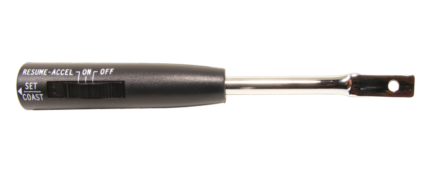
The resume bugs me. I don't remember a GM cruise using a resume in 1971. Here's a picture of what I would expect to see for a cruise lever, (Except the broken end.)
I want to see what Allan has to say about that JB kit,
What I see under the hood looks like GM stuff. I will not swear they are the right parts for that year.
What I see under the dash IS NOT GM wiring. The crimp connectors on the brake light switch IS NOT factory. The wire plugs into the fuse block ARE NOT factory. The white 4 wire connector next to the inline fuse does not look like a GM connector. That wire harness has too much extra wire, GM did not waste wire. Consider 2 inches of wire times hundreds of thousands of cars times pennies. It adds up. GM wrapped their wire harnesses.
I think something is cobbled up on this and/or it is a mix of factory and aftermarket parts. So I'm not sure what to tell you to do.
The resume bugs me. I don't remember a GM cruise using a resume in 1971. Here's a picture of what I would expect to see for a cruise lever, (Except the broken end.)
April 10th, 2012 | 05:24 AM
#20
Registered User
Joined: Feb 2008
Posts: 11,798
From: Plano, TX
That lever is definetly not factory for that year. It would be all chrome with one button at the end.
It does look like a mix of factory (various years given the servo) and aftermarket pieces.
Has this system ever worked?
It does look like a mix of factory (various years given the servo) and aftermarket pieces.
Has this system ever worked?
April 10th, 2012 | 06:10 AM
#21
Thread Starter
Registered User
Joined: Feb 2012
Posts: 537
From: Alberta
Lady72.....and others thanks for taking the time to help me with this!!!!
As for it working in the past...I dont know.......The previous owner said it didnt work and didnt say why!!!!
He said his mechanic friend went through this car after he bought i I t....total BS.....or his friend was a bad mechanic!!!!
I found a few little things that I now have fixed through the help of people on this site....Vacuume hose routing.....Oil pressuer sensor......just little things.....The car runs great and I realy enjoy it!!!
If I dont get this working Its no big deal....just would be nice on long drives!!!!
Thanks
Roger
April 10th, 2012 | 06:42 AM
#22
Registered User
Joined: Feb 2008
Posts: 11,798
From: Plano, TX
Glad everything else is working well.
It is very difficult to troubleshoot a system like this over the internet, especially when it is aftermarket or Frankensteined.
You know the servo holds vacuum, so thats good. The regulator could be leaky, as the seals in them fail over time due to deterioration. I have one on my kitchen counter that leaks and needs resto. Maybe I will overhaul it this summer. I really want to get mine working, also. The one on the car now looks like it went down with the "Titanic" and the innards are corroded beyond resto.
April 10th, 2012 | 02:33 PM
#23
Just an Olds Guy
Joined: Jul 2008
Posts: 24,525
From: Edmonton, AB. And "I am Can 'eh' jun - eh"
Well, couple of comments.
1. Absolutely that transducer is GM (actually perfect circle) and has the proper 3 pin connector. (I'm using a 72 OLDS Cruise schematic on this so bear with me if it gets wierd) On GM, pink is the power feed - on yours, white appears to be the power feed. GM Brown is the brake circuit. GM Blue is the transducer solenoid power. Only 2 vacuum lines is right with speedo and trans cables.
2. That cruise attachment on the stalk looks exactly like the aftermarket one I had for my 72. Roger, can't tell from the pics - too dark - but is it clipped to the stalk, with a separate thick wire running down the length of the column?
3. Aftermarket cruise DID offer the resume feature. GM did not, until much later - around 77 or 78?
4. There's no question this is a frankecruise. But I'm sure it's fixable.
5. The line to the servo, and the line to the vacuum source is correct.
6. The brake disconnect from GM goes directly to the brake switch. The one for this unit appears to be that relay in the first series of pictures. My guess is that the relay coil energizes with the 'on' switch, then closes when it recieves a 'set point signal from the 'set' button or 'resume' switch. It should open when it recieves a signal from the brake switch and denergize the coil when the unit is turned to the 'off' postion. Kind of neat; the brake interrupt will not affect the holding postion of the vacuum switch in the modulator, and that's what allows the 'resume' to work. So it should be getting 12 volts when: cruise is on and set, or resume activated. Otherwise should be 0 volts.
Just curious, when you engaged 'resume' you said it pulled 12v. Does it also pull 12v when you pressed 'set'? You could have a crossed wire here.
The brown wire should activate the brake release
The blue wire should be the one that activates the relay for 'set' and 'resume'? *guessing on the blue wire, but for sure on the brown*
The green wire should not be getting 12v in both on and off positions. I suspect some of your trouble is here...
The way I'm seeing this:
The yellow wire should probably be the SET wire and the green should be RESUME. Right now if you're getting a signal from the resume? There's nothing to resume because the cruise hasn't been set for a speed yet. That make sense to you?
Let's start small on this and work it out.
Last edited by Allan R; April 10th, 2012 at 02:35 PM.
April 10th, 2012 | 07:10 PM
#25
Thread Starter
Registered User
Joined: Feb 2012
Posts: 537
From: Alberta
Well looked at this some more and here's what up.....
when i remove the green wire from the back of the speedostat....it just pushes on over a screw ( ground I guess) I loose all power to the 4 wire plug to the cruise switch!!
DSC08226.jpg
Then to the fancy fuse thing....the black wire goes to ground and the white is the 5 amp fuse wire that goes to the brake switch
red goes to cruise switch
purple is my power wire
DSC08224-1.jpg
DSC08223-1.jpg
April 12th, 2012 | 08:04 PM
#26
Just an Olds Guy
Joined: Jul 2008
Posts: 24,525
From: Edmonton, AB. And "I am Can 'eh' jun - eh"
Roger, I did some more research on this cruise unit. The cruise switch you have on the car looks like the Rostra model. This look familiar?
Now comes the good and bad. This cruise control was manufactured by Rostra but is no longer produced. Either that special relay is needed to make this system work, or you need a special Rostra 3 pin switch. (The unit I had on my 72 did have on/off/resume but had a different type of switch attachment. It did work well)
On their electronic units some of their wiring does require one of the wires to be hot at all times. Rostra customer support (from what I've seen on the web) is good and they should be able to help with the problem you're having. It would be more appropriate for you than me to contact them and advise you need the installation/troubleshooting manual for their unit. Let them know that the tranducer is GM (actually it's made by Perfect Circle and is a 3 pin unit with a ground where your green wire is attached), but the other parts are Rostra. Also, they could advise how the adapter should be used with the modulator you have. They may be able to send you an efile of the installation guide.
A Ron Francis Wiring pdf on the CC60
Control Switch Wiring
GM original cruise control switch (open circuit style switch): Note: This unit will only work on four wire GM switches. A three wire switch will not work with this unit. ( A Rostra control switch will have to be used if you have a three wire GM switch). Three wire switches can be found in "some" 1974 and older vehicles.
GM original cruise control switch (open circuit style switch): Note: This unit will only work on four wire GM switches. A three wire switch will not work with this unit. ( A Rostra control switch will have to be used if you have a three wire GM switch). Three wire switches can be found in "some" 1974 and older vehicles.
I looked at several of their units that are electronic. The wiring colors seem to match the one you have, but not the way yours are set up.
I'm not copping out on this, simply trying to get the best source of troubleshooting available - from the people who made it. This is Rostra's customer service contact page (info at bottom of page). http://www.rostra.com/main/contact-rostra.html
Let us know what they say. If they can't send you good information we'll still work this out logically.
April 18th, 2012 | 01:17 PM
#29
Just an Olds Guy
Joined: Jul 2008
Posts: 24,525
From: Edmonton, AB. And "I am Can 'eh' jun - eh"
Roger, I believe your Red, Green and ground wires are the problem. According to Rostra/Audiovox,
the RED should be 12VDC at all times.
Black is always Ground
The Green wire should be 12VDC when Set is pressed, 0 when Set is released.
The Yellow wire should be 12VDC when Resume is pressed, 0 VDC when Resume is released.
Brown should be 12 VDC when ignition / Cruise is ON and 0 VDC when ignition / Cruise is Off.
Purple should be 12VDC when brake switch is pressed, 0VDC when brake switch released.
Sent you an email.
April 18th, 2012 | 04:57 PM
#33
Just an Olds Guy
Joined: Jul 2008
Posts: 24,525
From: Edmonton, AB. And "I am Can 'eh' jun - eh"
 April 18th, 2012 | 07:30 PM
#36
Registered User
Joined: Feb 2008
Posts: 11,798
From: Plano, TX
April 18th, 2012 | 07:50 PM
#37
Registered User
Joined: Apr 2012
Posts: 196
From: Salinas CA
 April 18th, 2012 | 07:54 PM
#38
Registered User
Joined: Apr 2012
Posts: 196
From: Salinas CA
thanks, its in the electrical thread. my problem is finding a 12v hot lead for my distributor from my ignition. its a HEI .
April 19th, 2012 | 05:10 AM
#39
Registered User
Joined: Feb 2008
Posts: 11,798
From: Plano, TX

Thread
Thread Starter
Forum
Replies
Last Post
mruders
General Discussion
1
February 4th, 2014 08:15 AM


