
Olds 455 vacuum identification and diagram
 August 2nd, 2010, 03:27 PM
#1
Registered User
Thread Starter

Join Date: Jul 2010
Location: North Carolina
Posts: 20
Olds 455 vacuum identification and diagram
Ok Guys, this is what I am looking at. I have an Olds 455, block number 396021Fa, which from the research that I have done, puts it between 1972 and 1974. I have been looking for a vacuum diagram but have only found one for 1976 and newer.
If I could get some questions answered about a few connections, I could easily figure out what should go where. From what I gather, this motor was pulled from a Cutlass Supreme, but I could be wrong. I have attached some pictures with annotations for a little help.
As you can tell from the photos, the guy I got it from before made a real mess out of the engine bay. Plus the motor/vehicle has been sitting for several years in an open field. Either the previous owner lost interest or wasn't too mechanically inclined. Either way, please have a look at the photos and help answer my questions.
Currently the 455 does run, although it is quite difficult to get started. Once it is running, it does great.
 August 2nd, 2010, 07:45 PM
#2
Registered User

Join Date: Jun 2009
Location: southeastern Michigan
Posts: 14,432
Here goes:
Picture #1 is the "ported vacuum switch" or "thermal vacuum switch." You can buy them at Autozone and certainly other places as well. On a 1973, which is what I have the service manual for, on both a 350 or 455 engine with a 4-bbl carburetor, the top port connects to the distributor vacuum advance, the middle port connects through something called the "distributor thermal check and delay valve" to the vacuum port to the right side of the fuel inlet line as shown in your third photo, and the bottom port connects to the long end of a T-fitting. One side of the T-fitting goes to the transmission vacuum modulator, and the other side just goes to a vacuum port on the intake manifold in front of the carburetor.
The purpose of this valve is control the amount of vacuum imposed on the distributor vacuum advance. Below 50 degrees F, the valve is fully open, and the vacuum advance receives full "distributor ported vacuum" from the carburetor. Above 50 degrees, the valve is in the "restricted" position, meaning that the orifice is only 0.005" in diameter. It takes up to 40 seconds for full vacuum advance in this position. Above 226 degrees coolant temperature (remember, this thing is screwed into the block where coolant flows, so it senses coolant temperature), the valve is bypassed altogether as the thermal vacuum switch switches to a different position and vacuum for the vacuum advance now comes directly from the port on the intake manifold.
The above paragraph is taken pretty much word for word from the service manual, and I'll admit it's a bit of mumbo jumbo to me. I don't know what the consequences are of not having the thermal check and delay valve in terms of how the engine runs, but I think you're better off with the vacuum hoses connected even without it as your distributor vacuum advance obviously needs vacuum!
In picture #2, you apparently have TWO taps for coolant temperature sensors. It looks like a previous owner added an aftermarket temperature gauge but drilled and tapped a new hole for it instead of using the one that was there. So you probably also have the temperature gauge as well. Do you actually have both, and do they both work? Anyway, the one you drew a box around is the original sensor that has only a wire that goes to the dash gauge. The one on the left looks to be the sensor and line for the aftermarket gauge.
The thing in front of those two looks to be your oil pressure sensor, and it looks as though the original sending unit was replaced with a tap for an aftermarket oil pressure gauge. Bet you have one of those, too. Does it work?
For picture #3, I've already mentioned what I think the right port is for. I think the left port goes to your EGR valve, which is the thing you've circled in your 5th photo. This vacuum line should pass through something called an "EGR control valve," but I've not been able to find one of these, either, and I'm guessing that you should just connect this port to the EGR valve and not worry about the control valve.
As far as photo #4, I don't know. Maybe someone else will chime in.
As I say, these hose routings are what are shown for a 1973 350 or 455 V8 with a 4-bbl carb. I don't know if they're the same for 1972 or 1974.
Last edited by jaunty75; August 2nd, 2010 at 08:22 PM.
August 2nd, 2010, 08:17 PM
#3
Registered User
Join Date: Jun 2009
Location: southeastern Michigan
Posts: 14,432
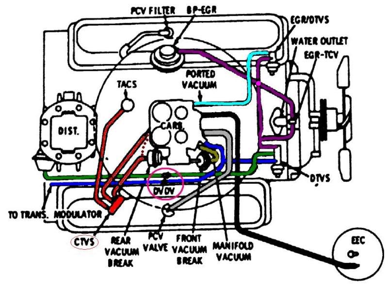
I've attached a scan of the figure in the manual showing the vacuum hose routing. I hope it helps. I apologize for the kind of poor quality of the scan. It's hard to get the pages, especially the edge near the binding, close to the scanner platen. Unfortunately, this figure is on the inside edge of the page.
Last edited by jaunty75; August 2nd, 2010 at 08:20 PM.
August 2nd, 2010, 09:09 PM
#4
Registered User
Thread Starter
Join Date: Jul 2010
Location: North Carolina
Posts: 20
Picture #1 is the "ported vacuum switch" or "thermal vacuum switch." You can buy them at Autozone and certainly other places as well. On a 1973, which is what I have the service manual for, on both a 350 or 455 engine with a 4-bbl carburetor, the top port connects to the distributor vacuum advance
... and the bottom port connects to the long end of a T-fitting. One side of the T-fitting goes to the transmission vacuum modulator, and the other side just goes to a vacuum port on the intake manifold in front of the carburetor.
In picture #2, you apparently have TWO taps for coolant temperature sensors. It looks like a previous owner added an aftermarket temperature gauge but drilled and tapped a new hole for it instead of using the one that was there. So you probably also have the temperature gauge as well. Do you actually have both, and do they both work?
The thing in front of those two looks to be your oil pressure sensor, and it looks as though the original sending unit was replaced with a tap for an aftermarket oil pressure gauge. Bet you have one of those, too. Does it work?
For picture #3, I've already mentioned what I think the right port is for. I think the left port goes to your EGR valve, which is the thing you've circled in your 5th photo. This vacuum line should pass through something called an "EGR control valve," but I've not been able to find one of these, either, and I'm guessing that you should just connect this port to the EGR valve and not worry about the control valve.
As far as photo #4, I don't know. Maybe someone else will chime in.
As I say, these hose routings are what are shown for a 1973 350 or 455 V8 with a 4-bbl carb. I don't know if they're the same for 1972 or 1974.
As I say, these hose routings are what are shown for a 1973 350 or 455 V8 with a 4-bbl carb. I don't know if they're the same for 1972 or 1974.
August 2nd, 2010, 09:31 PM
#5
Registered User
Thread Starter
Join Date: Jul 2010
Location: North Carolina
Posts: 20
I did run across a a fairly clear diagram on another forum a little while ago. It is for a Rocket 350 year unknown. Seen here:
vacuumdiagram.jpg
This coupled with the Vacuum diagram located at Autozone, I am getting a better understanding of what should be where. I am just curious as to the importance of some of the things missing on my motor as compared to what the diagrams say. I am going to go talk with my motor guy tomorrow and see what he has to say.
Last edited by Frankenstien; August 2nd, 2010 at 09:32 PM. Reason: deleted empty image tags
August 3rd, 2010, 04:39 AM
#6
Registered User
Join Date: Jun 2009
Location: southeastern Michigan
Posts: 14,432
Only the third one is familiar to me, and it's the only one shown on my diagrams. For your engine to use all three, it would have to have three tapped holes into the block or somewhere to sense the coolant temperature. Does your engine actually have all three or a place for all three? If not, then I would think this diagram would not be that useful to you.
August 3rd, 2010, 08:53 AM
#7
Registered User
Thread Starter
Join Date: Jul 2010
Location: North Carolina
Posts: 20
Since you mention that the vacuum switches must be able to sense the coolant temperature, it makes perfect sense now. The spot where the after market temperature gauge is located should have actually been a place for one of the vacuum switches, specifically the CTVS (ported vacuum switch).
I have three location in the intake manifold where this diagram would be useful.
1)The TACS port, located directly behind the carb currently has a line from the front side of the carb connected to it and the second line goes to the transmission.
2) The ported vacuum switch located at the in front of the carb passenger side of the intake manifold (which currently has nothing plugged into it).
3) and finally the last plug on the drivers side of the intake just in front of the carb (which currently has either the after market temp gauge and/or the factory gauge for my truck, one of which will be removed.)
I will need to stop by the auto part store to pick up a couple of valves. In the process of reading, studying, and considering your input, I have gotten a great understanding of the emission system. The great thing is my state doesn't require the emission for my age vehicle.
For your engine to use all three, it would have to have three tapped holes into the block or somewhere to sense the coolant temperature.
1)The TACS port, located directly behind the carb currently has a line from the front side of the carb connected to it and the second line goes to the transmission.
2) The ported vacuum switch located at the in front of the carb passenger side of the intake manifold (which currently has nothing plugged into it).
3) and finally the last plug on the drivers side of the intake just in front of the carb (which currently has either the after market temp gauge and/or the factory gauge for my truck, one of which will be removed.)
I will need to stop by the auto part store to pick up a couple of valves. In the process of reading, studying, and considering your input, I have gotten a great understanding of the emission system. The great thing is my state doesn't require the emission for my age vehicle.
August 3rd, 2010, 12:12 PM
#9
Old(s) Fart
Join Date: Mar 2007
Location: Northern VA
Posts: 48,255
I did run across a a fairly clear diagram on another forum a little while ago. It is for a Rocket 350 year unknown. Seen here:
This coupled with the Vacuum diagram located at Autozone, I am getting a better understanding of what should be where. I am just curious as to the importance of some of the things missing on my motor as compared to what the diagrams say. I am going to go talk with my motor guy tomorrow and see what he has to say.
This coupled with the Vacuum diagram located at Autozone, I am getting a better understanding of what should be where. I am just curious as to the importance of some of the things missing on my motor as compared to what the diagrams say. I am going to go talk with my motor guy tomorrow and see what he has to say.
You didn't say what year/model car this was in. That will govern what needs to be hooked up.
The Fa block casting was used from 1972 through 1976. The VIN derivative stamped on the side of the block will tell you the exact year, but that's really not important.
First, if the car has trouble starting but runs fine when warm, your choke likely needs to be adjusted. That's probably unrelated to any vacuum hose issues.
The TVS in photo one is not needed if you run straight manifold vacuum to the vacuum advance canister. Ports on the carb may be manifold vacuum or may be ported vacuum. Use a vacuum gauge to tell them apart (ported is zero at idle and goes up just off idle, manifold is high at idle).
The EGR valve (mislabled PCV in your photo) is not needed if you don't want it. Most folks unbolt is and use a cover over the holes. The EGR tells us that the motor is 1973-76 vintage (I'm guessing it has J heads also).
Depending on the car, you only need a handful of vacuum lines to allow the engine to run. One from the distributor vacuum advance can to manifold vacuum. One for the power brakes. One to the transmission vacuum modulator.
If you have a stock air cleaner with the thermal flapper in the snorkel there will be a connection from the air cleaner housing to manifold vacuum.
If you have A/C you'll need a connection from the A/C vacuum reservoir to manifold vacuum to allow the flapper doors in the HVAC system to work.
If you have cruise control you'll need a manifold vacuum connection to the cruise actuator.
If you have a vacuum power trunk or power door locks you'll need a connection for those.
In reality, most of the connections to the carb are related to the 1973-76 emissions connections and are not required. Capping them is fine.
August 3rd, 2010, 01:17 PM
#10
Registered User
Thread Starter
Join Date: Jul 2010
Location: North Carolina
Posts: 20
You didn't say what year/model car this was in. That will govern what needs to be hooked up.
First, if the car has trouble starting but runs fine when warm, your choke likely needs to be adjusted. That's probably unrelated to any vacuum hose issues.
The EGR valve (mislabled PCV in your photo) is not needed if you don't want it. Most folks unbolt is and use a cover over the holes. The EGR tells us that the motor is 1973-76 vintage (I'm guessing it has J heads also).
Ports on the carb may be manifold vacuum or may be ported vacuum.
Last edited by Frankenstien; August 3rd, 2010 at 01:23 PM.
August 3rd, 2010, 02:11 PM
#11
Old(s) Fart
Join Date: Mar 2007
Location: Northern VA
Posts: 48,255
THAT is the source of lengthy debates on motorhead websites. For non-stock installations, I usually say to try them both and go with what works best for that particular installation. If you do run ported to the distributor, then you do want a thermal vacuum switch in the cooling system that will supply full vacuum if the engine starts to overheat. That's what the factory did, since additional advance at idle will let the engine run a little cooler.
August 6th, 2010, 12:56 PM
#12
Junior Member
Join Date: Oct 2004
Location: Southern CA
Posts: 2,212
Norm
August 10th, 2010, 03:42 PM
#13
Registered User
Join Date: Feb 2010
Location: West Michigan
Posts: 1,587
Hooking up the vacuum advance directly to manifold vacuum can (depending on many factors) yield improved idle quality and higher idle speed, allowing you to close the throttle blades further, which can solve some other carburetion tuning problems.
It also means that the ignition is already advanced as you come off idle (instead of waiting for the vacuum advance can to catch up), which can improve part throttle response, which is where you do 95% of your driving, right?
But maybe those are emotional reasons instead of logical.
 August 11th, 2010, 06:27 PM
#14
Junior Member
Join Date: Oct 2004
Location: Southern CA
Posts: 2,212
How can throttle response be "improved" by removing ignition advance?
Emotion has no place in a rational discussion, while simple logic is an important part of any learning process.
Norm
August 17th, 2010, 03:26 PM
#15
Registered User
Join Date: Feb 2010
Location: West Michigan
Posts: 1,587
I'm talking about how the transfer slot gets drained of fuel if the throttle blades are too far open at slow idle. This causes a slight stumble as you come off idle. Having the blades too far open can also draw fuel from the venturi when it should only be coming from the idle circuit.
I should have been clearer. If using manifold vacuum instead of ported vacuum, you may want to use a vacuum canister with less advance and/or use less initial advance. Or not. Tell me, what is "proper" mechanical advance for a given idle speed? Different cam, compression ratio, intake manifold, exhaust, fuel type, air/fuel mixture, etc. (ie, all the factors I was aluding to) make one engine "want" more or less advance at idle than another engine. All I was trying to do was encourage people to experiment. There is no one right or proper answer.
Not usually. As long as you don't push too far on the pedal, the increased RPMs actually build more vacuum than you had at idle. Again, this depends a lot on your cam. Of course, as you open the throttle further and further, the vacuum (and advance) does start to fall.
Are you implying that the wait is good because the effect of the accelerator pump and power valve are also not instantaneous? I guess that could be true. But why are we talking about power valves? This is a quadrajet, right?
You misunderstand. I was saying throttle response is improved by the fact that the ignition is already advanced as you come off idle, instead of waiting for it to catch up. This assumes, of course, that it isn't so far advanced as to ping.
Who said anything about being rational? 
Hopefully you find my reasoning logical.
If the mechanical (centrifugal) advance is already proper for a given idle speed, how would more (via added vacuum) be beneficial?
As you come off idle, vacuum (and advance) goes away.
How would this "wait" affect the operation of the accelerator pump and power valve?
How can throttle response be "improved" by removing ignition advance?
Emotion has no place in a rational discussion, while simple logic is an important part of any learning process.
Hopefully you find my reasoning logical.
August 17th, 2010, 10:25 PM
#16
Junior Member
Join Date: Oct 2004
Location: Southern CA
Posts: 2,212
Good post. A welcome change from the "mine is bigger than yours" style of debate we have been seeing lately.
These are not normal conditions. I would be looking for the cause, not a band-aid.
Proper = What that particular engine needs for its intended application. For most owners, factory specs are sufficient. For many of us, a custom curve is preferred.
Nothing wrong with experimentation. It is how I found out why the Olds engineers did it the way they did.
There is a right answer. It is the one that works best for that unique application and it will be based on a "proper" advance curve.
Increased RPM = more load = less vacuum = less advance.
Of all the factors, cam timing has the most effect on initial advance. If "initial" advance is optimum for that application, "ported" vacuum will compliment the transition from idle to power.
Once it is above idle, the canister is exposed to "manifold" vacuum, regardless of the original source, which moves it beyond the scope of this discussion.
There should be no wait. The effects of vacuum advance and power valve are instantaneous. It takes time for the pump shot to get to the combustion chamber.
Does the Q-jet not have a power valve?
The act of "coming off idle" lowers vacuum and takes away advance at the time it is most needed.
When the throttle is opened, a lean condition is created which is compensated by a "shot" of fuel from the accelerator pump. This creates a momentary "lean condition" while the fuel travels to the combustion chambers.
At this point, we have two choices:
Norm
........ the transfer slot gets drained of fuel if the throttle blades are too far open at slow idle. This causes a slight stumble as you come off idle. Having the blades too far open can also draw fuel from the venturi when it should only be coming from the idle circuit ........
........ what is "proper" mechanical advance for a given idle speed? Different cam, compression ratio, intake manifold, exhaust, fuel type, air/fuel mixture, etc. (IE, all the factors I was alluding to) make one engine "want" more or less advance at idle than another engine ........
There is a right answer. It is the one that works best for that unique application and it will be based on a "proper" advance curve.
Of all the factors, cam timing has the most effect on initial advance. If "initial" advance is optimum for that application, "ported" vacuum will compliment the transition from idle to power.
When the throttle is opened, a lean condition is created which is compensated by a "shot" of fuel from the accelerator pump. This creates a momentary "lean condition" while the fuel travels to the combustion chambers.
At this point, we have two choices:
- If the vacuum source is "ported" more advance will be added to "cover" that lean condition.
- If the source is "full time", all available advance is already being used and that momentary "lean condition" is exacerbated by a loss of advance and becomes a hesitation.
Norm
August 18th, 2010, 03:23 PM
#17
Registered User
Join Date: Feb 2010
Location: West Michigan
Posts: 1,587
Norm, I agree -- good debate. Unfortunately, it's your foundation which is flawed (some of it anyway). No offense intended, just as you meant none to me.
I don't want to draw this out much longer, but I'll just make a couple comments:
1/ A throttle blade too far open at slow idle, which then drains the transfer slot, is a very common problem (= normal condition) with quadrajets when people install a larger cam. Both Roe and Ruggles agree.
2/ Factory timing specs are sufficient? For a 40-year old engine which has been rebuilt with who knows what cam, pistons, head gaskets, carb, etc. and is running modern gasoline? Heck, even 40 years ago the factory recommended different timing specs in the Supertuning guide than they did on the tune-up label.
3/ In your cars you must run tiny little cams which actually develop more vacuum at idle than at cruise. My W-30 (with an unknown cam which acts a lot like the factory 328-degree cam), develops 7 inches of vacuum at idle. As I increase the rpms, vacuum rises to a max of 13 inches (at about 2000 rpm) before falling off as the throttle opens further. Even with small cams, I would expect more vacuum at, say, 1500 rpm than at 700. I'm talking small throttle openings as used in normal driving, not WOT.
4/ No a quadrajet does not have a "power valve." At least Rochester Products didn't call it that. It does have primary metering rods which move within the primary jets. Their position is continuously variable, depending on the vacuum signal. So I wouldn't call it a valve like Holley uses.
5/ Let's look at a very common scenario. Joe Blow puts a new cam in his Olds engine. Being a real man, he puts in more cam than he should've. For a timing curve, big cams generally perform better with more advance at both idle and low rpms. But you still don't want more than about 36 degrees mechanical advance. Of course, the proper thing to do is to recurve the distributor, modifying it so that the weights can't travel as far between the idle and high-rpm positions. But Joe Blow, not being the technical type (that's why he put in too much cam to begin with), doesn't know how to nor want to recurve his distributor. An easy solution is to hook up the vacuum advance canister to manifold instead of ported vacuum. His engine instantly gets maybe 5 - 15 degrees more advance at idle (depending on the cansiter and how much manifold vacuum there is at idle), yet the high-rpm advance stays the same. Is there a better solution? Probably. But this is an instant improvement in many cases.
Last edited by BlackGold; August 18th, 2010 at 03:27 PM.
August 18th, 2010, 04:41 PM
#18
Registered User
Join Date: Apr 2008
Location: new zealand
Posts: 537
Norm, I agree -- good debate. Unfortunately, it's your foundation which is flawed (some of it anyway). No offense intended, just as you meant none to me.
I don't want to draw this out much longer, but I'll just make a couple comments:
1/ A throttle blade too far open at slow idle, which then drains the transfer slot, is a very common problem (= normal condition) with quadrajets when people install a larger cam. Both Roe and Ruggles agree.
2/ Factory timing specs are sufficient? For a 40-year old engine which has been rebuilt with who knows what cam, pistons, head gaskets, carb, etc. and is running modern gasoline? Heck, even 40 years ago the factory recommended different timing specs in the Supertuning guide than they did on the tune-up label.
3/ In your cars you must run tiny little cams which actually develop more vacuum at idle than at cruise. My W-30 (with an unknown cam which acts a lot like the factory 328-degree cam), develops 7 inches of vacuum at idle. As I increase the rpms, vacuum rises to a max of 13 inches (at about 2000 rpm) before falling off as the throttle opens further. Even with small cams, I would expect more vacuum at, say, 1500 rpm than at 700. I'm talking small throttle openings as used in normal driving, not WOT.
4/ No a quadrajet does not have a "power valve." At least Rochester Products didn't call it that. It does have primary metering rods which move within the primary jets. Their position is continuously variable, depending on the vacuum signal. So I wouldn't call it a valve like Holley uses.
5/ Let's look at a very common scenario. Joe Blow puts a new cam in his Olds engine. Being a real man, he puts in more cam than he should've. For a timing curve, big cams generally perform better with more advance at both idle and low rpms. But you still don't want more than about 36 degrees mechanical advance. Of course, the proper thing to do is to recurve the distributor, modifying it so that the weights can't travel as far between the idle and high-rpm positions. But Joe Blow, not being the technical type (that's why he put in too much cam to begin with), doesn't know how to nor want to recurve his distributor. An easy solution is to hook up the vacuum advance canister to manifold instead of ported vacuum. His engine instantly gets maybe 5 - 15 degrees more advance at idle (depending on the cansiter and how much manifold vacuum there is at idle), yet the high-rpm advance stays the same. Is there a better solution? Probably. But this is an instant improvement in many cases.
I don't want to draw this out much longer, but I'll just make a couple comments:
1/ A throttle blade too far open at slow idle, which then drains the transfer slot, is a very common problem (= normal condition) with quadrajets when people install a larger cam. Both Roe and Ruggles agree.
2/ Factory timing specs are sufficient? For a 40-year old engine which has been rebuilt with who knows what cam, pistons, head gaskets, carb, etc. and is running modern gasoline? Heck, even 40 years ago the factory recommended different timing specs in the Supertuning guide than they did on the tune-up label.
3/ In your cars you must run tiny little cams which actually develop more vacuum at idle than at cruise. My W-30 (with an unknown cam which acts a lot like the factory 328-degree cam), develops 7 inches of vacuum at idle. As I increase the rpms, vacuum rises to a max of 13 inches (at about 2000 rpm) before falling off as the throttle opens further. Even with small cams, I would expect more vacuum at, say, 1500 rpm than at 700. I'm talking small throttle openings as used in normal driving, not WOT.
4/ No a quadrajet does not have a "power valve." At least Rochester Products didn't call it that. It does have primary metering rods which move within the primary jets. Their position is continuously variable, depending on the vacuum signal. So I wouldn't call it a valve like Holley uses.
5/ Let's look at a very common scenario. Joe Blow puts a new cam in his Olds engine. Being a real man, he puts in more cam than he should've. For a timing curve, big cams generally perform better with more advance at both idle and low rpms. But you still don't want more than about 36 degrees mechanical advance. Of course, the proper thing to do is to recurve the distributor, modifying it so that the weights can't travel as far between the idle and high-rpm positions. But Joe Blow, not being the technical type (that's why he put in too much cam to begin with), doesn't know how to nor want to recurve his distributor. An easy solution is to hook up the vacuum advance canister to manifold instead of ported vacuum. His engine instantly gets maybe 5 - 15 degrees more advance at idle (depending on the cansiter and how much manifold vacuum there is at idle), yet the high-rpm advance stays the same. Is there a better solution? Probably. But this is an instant improvement in many cases.
tx
mike
August 18th, 2010, 08:09 PM
#19
Junior Member
Join Date: Oct 2004
Location: Southern CA
Posts: 2,212
- W-30 = 0.474" 0.474" 328�/328� 244� 244�
- Mine. = 0.544" 0.544" 292�/300� 248� 258�
- Mine. = 0.560" 0.576" 302�/314� 252� 263�
- Mine. = 0.580" 0.555" 318�/328� 260� 254�
- Mine. = 0.584" 0.568" 310�/320� 266� 270�
........ My W-30 (with an unknown cam which acts a lot like the factory 328-degree cam) develops 7 inches of vacuum at idle. As I increase the rpms, vacuum rises to a max of 13 inches (at about 2000 rpm) before falling off as the throttle opens further. Even with small cams, I would expect more vacuum at, say, 1500 rpm than at 700. I'm talking small throttle openings as used in normal driving, not WOT ........
Another red herring. It uses a vacuum actuated piston that performs exactly the same function as its counterpart in any other carb, regardless of its manufacturer.
To do anything else would not be logical.
Norm


Thread
Thread Starter
Forum
Replies
Last Post
84oldsDelta88
Cutlass
15
January 3rd, 2012 02:57 AM
c.ostrander@sbcglobal.net
Tech Editor's Desk
1
October 17th, 2010 06:27 PM


