When you click on links to various merchants on this site and make a purchase, this can result in this site earning a commission. Affiliate programs and affiliations include, but are not limited to, the eBay Partner Network.
^^^THIS. The high speed power supply is completely separate from the low speed supply. The only common parts of the circuit are the motor, the wire from the high speed relay to the motor, the relay itself, the motor ground wire (on A/C cars only), the fan speed switch on the faceplate, the internal master switch, and the power to the control head (since this not only operates the low speeds directly but also operates the high speed relay).
The very first test is to see if the blower motor works. Pull the connector off the high speed relay and apply 12V to the purple wire in the connector. If the blower runs, the motor is good. If not, figure out why. Note that A/C cars have a separate ground wire from the motor to the firewall due to the fiberglass HVAC box. Heater-only cars use a metal box and don't need this wire.
Newbie question, I am having this issue (no blower motor at any speed). How do I apply 12v power to the purple connector wire from the hispeed relay?
...and assuming while I do this, the car has to be on and the fan switch has to be on high, to test?
Newbie question, I am having this issue (no blower motor at any speed). How do I apply 12v power to the purple connector wire from the hispeed relay?
...and assuming while I do this, the car has to be on and the fan switch has to be on high, to test?
Please create your own (separate) thread pertaining to your specific vehicle & issue. It's cumbersome to insert someone else posts into a thread which is over three years old. State what year & model vehicle, w/ AC or w/o AC.
Please create your own (separate) thread pertaining to your specific vehicle & issue. It's cumbersome to insert someone else posts into a thread which is over three years old. State what year & model vehicle, w/ AC or w/o AC.
Newbie question, I am having this issue (no blower motor at any speed). How do I apply 12v power to the purple connector wire from the hispeed relay?
...and assuming while I do this, the car has to be on and the fan switch has to be on high, to test?
The purple wire powers the fan motor directly. Simply pull the connector off of the relay and run a jumper from the purple wire in the connector to the + terminal of the battery. If the fan runs, the motor is fine and the problem is likely that relay. If not, then the motor is bad.
So i have searched the forums and done some basic checks.
i replaced the 30a fuse in the fuse block, I've checked the fuse going from the horn relay to the hi speed relay and it looks good.
I found the purple wire on the other side and the plug is connected well.
I read somewhere about jumping the purple wire. How do I apply 12v power to the purple connector wire from the hispeed relay? ..and assuming while I do this, the car has to be on and the fan switch has to be on high, to test?
The purple wire powers the fan motor directly. Simply pull the connector off of the relay and run a jumper from the purple wire in the connector to the + terminal of the battery. If the fan runs, the motor is fine and the problem is likely that relay. If not, then the motor is bad.
Awesome! Thank you! I appreciate it! I'll check it out.
OP may have been in the process of creating a new thread (at my suggestion) during the same time period as you created a separate thread for the OP? JS
The purple wire powers the fan motor directly. Simply pull the connector off of the relay and run a jumper from the purple wire in the connector to the + terminal of the battery. If the fan runs, the motor is fine and the problem is likely that relay. If not, then the motor is bad.
Originally Posted by joe_padavano
I merged your two threads. You aren't helping yourself by asking the same question in multiple threads.
The purple wire powers the fan motor directly. Simply pull the connector off of the relay and run a jumper from the purple wire in the connector to the + terminal of the battery. If the fan runs, the motor is fine and the problem is likely that relay. If not, then the motor is bad.
Thank you. I did the bypass like you said and the blower motor kicked on. Yay.
So just need a new relay. Amazing.
Thank you. I did the bypass like you said and the blower motor kicked on. Yay.
So just need a new relay. Amazing.
Before replacing the relay, I'd verify power on the appropriate terminals in the connector. The heavy black/orange wire should be powered at all times. The blue wire should be powered whenever the blower speed switch is in any of the low speed positions (though voltage will vary depending on the speed selected). The smaller black/orange wire should be powered when the speed switch is in the high position.
Before replacing the relay, I'd verify power on the appropriate terminals in the connector. The heavy black/orange wire should be powered at all times. The blue wire should be powered whenever the blower speed switch is in any of the low speed positions (though voltage will vary depending on the speed selected). The smaller black/orange wire should be powered when the speed switch is in the high position.
Thank you so much for this.
Ok, so the black orange has power.
The other 2 have no power with proper settings as you described.
So is it the actual switch selector behind the dash then?
Thank you so much for this.
Ok, so the black orange has power.
The other 2 have no power with proper settings as you described.
So is it the actual switch selector behind the dash then?
Could be the switch, could be the brown power feed to the switch. Again, trace the circuit, find the problem.
A great beginning point would be to evaluate/visualize the brown wire which is connected to the fuse panel. Validate power on the Brown wire to the switch. This is illustrated in both the 1970 color wiring diagram in the CSM & the IC-6 diagram (already posted above).
My 1970 wiring diagram isn't crystal clear in detail, but should provide you some information but you should review your own color wiring diagram in the CSM.
My 1970 wiring diagram isn't crystal clear in detail, but should provide you some information but you should review your own color wiring diagram in the CSM.
Unfortunately that wiring diagram only shows the base heater, not the optional A/C wiring.
That's true Mr. Joe, but as I previously stated, the OP has already been provided with the optional A/C wiring diagram which you provided and it specifically illustrates the brown wire routing.
Climb under the dash and locate the brown wire that feeds the HVAC control unit.
There's no way I can see that. Between my factory 8 track player and the ac vents with the lower vent pieces.
Ugh.
I would have to disassemble all the ac ducts and lower vents to get to try to see and find that wire.
Guess that's a project for another day.
Never can be simple.
Thanks for all your help though.
I'll update whenever I decide I want to tackle that project.
Honestly, the ductwork is surprisingly not that difficult to remove - three main pieces - the plenum distribution box and the two horizontal runners. They slide into each other quite easily.
Honestly, the ductwork is surprisingly not that difficult to remove - three main pieces - the plenum distribution box and the two horizontal runners. They slide into each other quite easily.
Ah ok, I can tackle that this weekend then.
Can you walk me thru the next steps once I locate the brown wire:
If I have power at the brown wire connection, then....
Look, with Joe already on board and the many other CO members you’re in good hands. Start from the outside in. Remove the screws (1/4” socket?) holding the horizontal duck work pieces, remove those then remove the plenum. Take your time, succumb to the idea it has to be done and simply resolve to the fact it’s a simple deal.
Tracing the Brown wire will be easiest w/ a test light. They’re $10 at most box stores. Alligator clips to a known good ground (e.g. chassis, metal dash, etc) then probe with the pointed end pointer directly into the wire. If the lamp lights you have power. If not, guess what.
Test/Circuit Light Tester. NOTE: The difference quality is primarily the tip of the stylus. A very sharply pointed stylus is most often a better quality tester since it allows you to probe into a wire with ease.
Tracing the Brown wire will be easiest w/ a test light. They�re $10 at most box stores. Alligator clips to a known good ground (e.g. chassis, metal dash, etc) then probe with the pointed end pointer directly into the wire. If the lamp lights you have power. If not, guess what.
so if i have power at the brown wire, them it's the relay in the engine bay?
If i don't have power at the brown wire, then it's the switch in the dash?
so if i have power at the brown wire, them it's the relay in the engine bay?
If i don't have power at the brown wire, then it's the switch in the dash?
Just trying to be clear
Thanks again
Again, look at the wiring diagram. The brown wire feeds the master switch on the control head, which in turn feeds the speed switch, which in turn feeds the resistor and the relay. The problem can be anywhere in those components or the wires or connectors between them. Get the test light and trace the circuit. Randomly replacing parts is a great way to waste time and money, not to mention the chance of introducing new and creative failure modes in the process. This isn't that complex a circuit.
SUGGESTION: Pick up a roll (or two) of black adhesive (double-sided sticky) fabric tape while grabbing a circuit tester. You likely are unaware of anyone who may have previously removed duct work, condition of the duct work (53 yrs old), you may find some pin holes, bad seams etc. which could use some uplifting to achieve/maintain good flow-through. You can find it in most general big box stores for far less $$ than an auto parts store. It may or may not be located in the electrical section next to electrical tape (it is not electrical tape). You can find the circuit tester in a big box store, as well (e.g. Lowe's, Home Depot, Ace, etc.) - most often far less $$ than an automotive store.
SUGGESTION: Pick up a roll (or two) of black adhesive (double-sided sticky) fabric tape while grabbing a circuit tester. You likely are unaware of anyone who may have previously removed duct work, condition of the duct work (53 yrs old), you may find some pin holes, bad seams etc. which could use some uplifting to achieve/maintain good flow-through. You can find it in most general big box stores for far less $$ than an auto parts store. It may or may not be located in the electrical section next to electrical tape (it is not electrical tape). You can find the circuit tester in a big box store, as well (e.g. Lowe's, Home Depot, Ace, etc.) - most often far less $$ than an automotive store.
Fabric Tape
Good idea, thanks.
Meanwhile i made a quick jumper wire connector for the high speed so i can have heat while in driving it to the car show tomorrow.
Then I'll work on removing the ducts this weekend and hunting for the elusive brown wire connector.
Again, look at the wiring diagram. The brown wire feeds the master switch on the control head, which in turn feeds the speed switch, which in turn feeds the resistor and the relay. The problem can be anywhere in those components or the wires or connectors between them. Get the test light and trace the circuit. Randomly replacing parts is a great way to waste time and money, not to mention the chance of introducing new and creative failure modes in the process. This isn't that complex a circuit.
Ok, i took down the vents and found the brown connector wire and the brown wire has power (it lit up with the test light).
Next idea please. Electrical is my least knowledge area of these cars. Thank you in advance.
Ok, i took down the vents and found the brown connector wire and the brown wire has power (it lit up with the test light).
Next idea please. Electrical is my least knowledge area of these cars. Thank you in advance.
So trace the circuit. This is troubleshooting 101. If you are getting power to the control head, but nothing out of the control head, then the problem is the master switch, the blower speed switch, or the wiring in between. This means either getting under the dash or removing the control head.
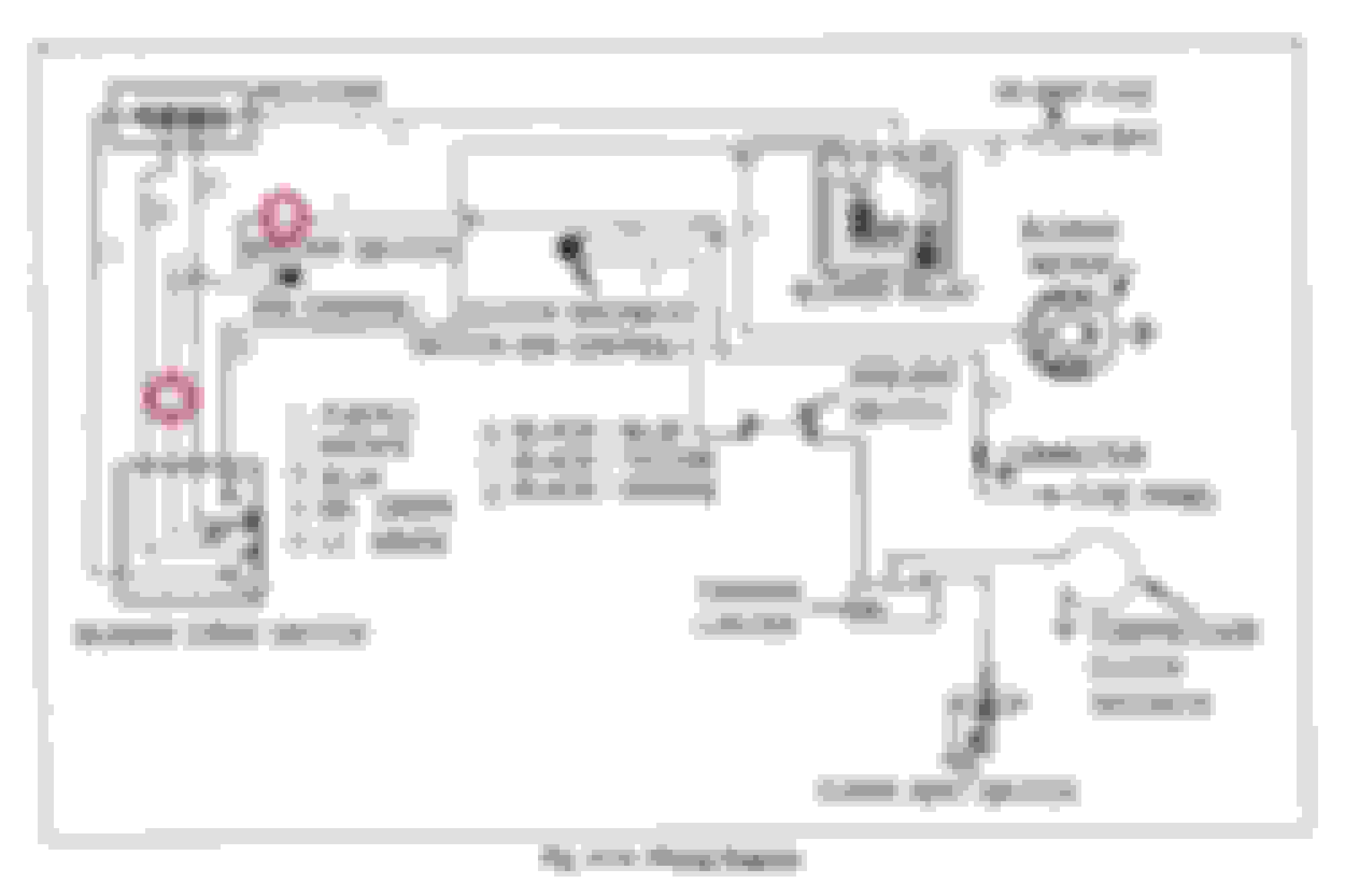
Read Post #30. Follow the circuit. In the simplest of terms, you must 1st determine Power on both sides of the Master Switch on the Control Head (red circles). Do you have power at both (red circle) locations?
Scroll up to post #31 for photos of the master switch. You can disconnect the two wire connector on that master switch and jumper across the terminals in the connector. If the fan works, you've found the problem. Of course you need to reconnect everything else that has been disconnected first (like the brown power wire).
Scroll up to post #31 for photos of the master switch. You can disconnect the two wire connector on that master switch and jumper across the terminals in the connector. If the fan works, you've found the problem. Of course you need to reconnect everything else that has been disconnected first (like the brown power wire).
I Did notice the inline fuse in the engine bay that goes from the side of the fender relay to the blower relay only had a 25a fuse in it. That wouldn't cause any issues would it? I saw you said it should be a 30a fuse. Can i just swap in a 30a fuse instead?
I Did notice the inline fuse in the engine bay that goes from the side of the fender relay to the blower relay only had a 25a fuse in it. That wouldn't cause any issues would it? I saw you said it should be a 30a fuse. Can i just swap in a 30a fuse instead?
The fuse is a safety device which will/should blow to protect the circuit. You don't want to go OVER the designated rating of the 30A fuse . If you're 5A below the designated rating and the fuse is not blown then it's providing power. With that said, you should change the fuse to a 30A fuse to ensure a lesser Amp fuse doesn't blow. It will not harm the wiring circuit as long as it is not blown.
I Did notice the inline fuse in the engine bay that goes from the side of the fender relay to the blower relay only had a 25a fuse in it. That wouldn't cause any issues would it? I saw you said it should be a 30a fuse. Can i just swap in a 30a fuse instead?
If you have power on that heavy black/orange wire at the relay, then this is completely unrelated to your issue. Think this through. You have power going into the control head, you do not have power coming out of the control head. That REALLY narrows down the location of the problem. Logic is your friend here.
 November 22nd, 2023, 01:21 PM


")