When you click on links to various merchants on this site and make a purchase, this can result in this site earning a commission. Affiliate programs and affiliations include, but are not limited to, the eBay Partner Network.
I am about to replace a bunch of suspension parts including control arm bushings. I have wanted disc brakes on the front for a while and figure this is likely going to be a good time. Currently I have 4-wheel power drums.
I found a great post from Joe here and I think it answered most of my questions, with the main one being what (if anything) needed to be done with the existing booster and master cylinder. If I understand right, the booster is fine, I just need a new master cylinder and valve. So, here is what I have so far:
https://www.summitracing.com/parts/leb-fc1002sm
https://www.summitracing.com/parts/dhb-m76162
https://www.summitracing.com/parts/sum-760186
I think that will get me all the main components, a master cylinder and valve for front disc rear brake setup. Then I would just have to rework or redo the brake lines. Anyone have anything else I am missing or any bad reviews on this kit?
I was also wondering if there is a gasket between the master cylinder and booster. I'm finding conflicting information online about that one. I think after that I should now have everything I need. If I have to get new brake lines I should be able to pick those up locally.
The rubber seal between the M/C and booster is mandatory and a good thing to replace. Unfortunately they are not readily available. The only place I've seen them is from Corvette specialty vendors.
Harmon Classic Brakes sells a booster "refresh" kit, which includes all the soft parts you can replace without separating the booster halves. They might sell the cup seal separately but don't show it on line. Their seal part number is 62-285.
Wow, these are some difficult pieces to find. In your post that detailed the affordable disc brake conversion I think you mentioned that the clips can be modified to suit. If I can't find new ones that may be and option
What are the odds of getting the existing booster seal out without damage and reusing it? I think that might be the real problem here.
Yes, you can grind the brackets to fit, but Inline and others sell them.
Personally I've never replaced that seal, but a bad seal can cause a vacuum leak.
The last pieces needed (I hope) are those brackets and they are coming tomorrow.
I was at a car show this weekend and was looking at how others connected all the brake lines for the new master cylinder and valve. I was planing to put the valve on the frame which some did, but others used a bracket and have it right up near the master cylinder. Is there any advantage of doing this?
The other thing I noticed was some have what looks like a lot of extra brake line coiled up near the master cylinder. Is this trying to equalize pipe distances between the front wheels? Maybe it's acting like a heat sink or something? Not all did it so I assume it's not needed, but if it has a good reason I can do it.
And last, the electrical test port. I saw a few that had a connection to it going to a wiring harness. I assume this is just wired up to a dash light?
Other than that I think I'm all ready to dig into this.
The loops in the lines near the M/C provide flexibility to allow for manufacturing tolerances in mounting the body to the frame. Line length is irrelevant for brake function once the system is bled.
So I think everything is together now. Just doing the master cylinder now. Is there a way to verify that the rod that activates the master cylinder is the correct length? I think this was already confirmed based on year and model but a quick verification is always nice.
Also looking at the instructions that came with the master cylinder it notes to "bench bleed" the thing first. Is this needed or just a step that makes bleeding the system easier later? I would just do it but I don't have a vice which makes this step difficult. If I can just bleed the whole system on the car without issues that will probably be easier in my case
Finally got everything to finish the job. Brake lines had a lengthy hold up at the border.
Two things after doing some reading. My Chilton's manual says to bleed do left front, right front, left rear then right rear but pretty much everything I find online says to start with the furthest wheel and work to the closest. What have you guys done?
Last I read something about the proportioning valve getting messed up during bleeding and being tough to fix and that a "spring loaded plunger on the front proportioning valve should be depressed with a wire or tape". I don't see anything like that on mine. It is this one from summit. It is a "fixed" type so maybe that for a different kind? https://www.summitracing.com/parts/sum-760186
First, throw that Chiltons as far as you can and get a real factory Chassis Service Manual.
Second, the brake system is split front to back. It doesn't matter which end you start with, the two aren't plumbed together.
Third, pushing the differential pressure piston all the way to one side during bleeding is a real possibility if you use too much pressure. Unfortunately, that plunger has nothing to do with this. The plunger is used on factory combo valves to disable the metering valve in the front brake circuit during bleeding. It has no effect on the differential pressure piston, and frankly in half a century of working on these cars I've never bothered with it. The thing you really want is this tool that screws in place of the differential pressure switch contact and locks the piston in place while you bleed the brakes to avoid the problem.
My Chilton's manual says to bleed do left front, right front, left rear then right rear but pretty much everything I find online says to start with the furthest wheel and work to the closest. What have you guys done?
Leave the Chilton's Manual in an outhouse somewhere where it will serve some good...
Ok, so I need some more help.... I know, what else is new, lol.
After a lengthy delay at the border with my brake lines they and the proportioning valve are on the car. I got that bleeder tool for the valve and it is on the car too. I thought it would be simply bleeding the brakes but that's not going as expected. I started using the method of having someone build pressure on the brakes and cracking the bleeder screw at the right rear. Nothing, not even air seemed to be coming out. I tried the fronts to see if I could get anything there and both fronts have fluid.
I then bought the vaccum pump thinking that might work. I get up to about 15-20" of vacuum and crack the screw. Pressure goes down but after doing it many times no fluid and the master cylinder doesn't go down either. I was trying to find where a blockage might be so I backed the rear line at the proportioning valve off and had lots of fluid come out there. Any ideas what is going in here?
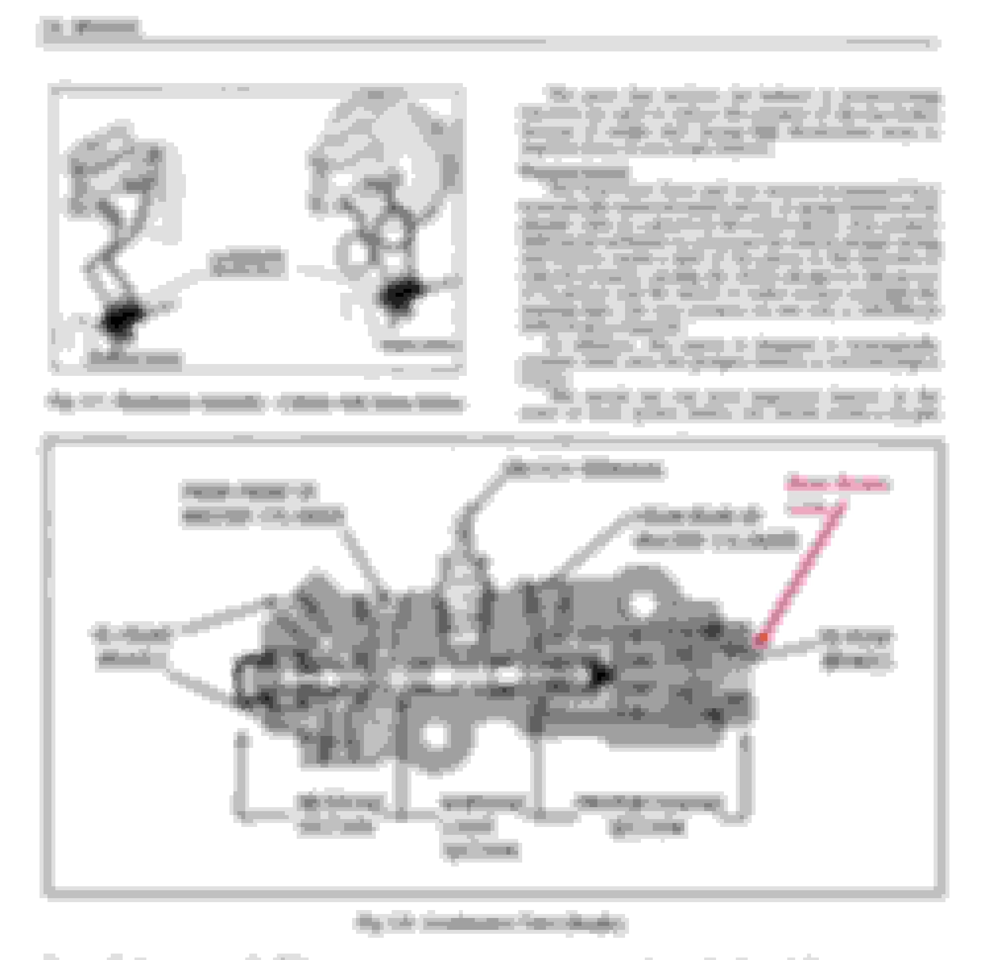
To ensure we're on the same page, the brake line you removed from the combination valve is the rear brake line attached to the rear of the combination valve as depicted by the arrow in the illustration (below), correct?
With the rear brake line removed from the combination valve, push down on the brake pedal several times, you should notice appreciable amounts of brake fluid coming out the rear of the combination valve. Does fluid flow from the rear of the combination valve? If yes, then the blockage is somewhere in the rear brake line past the combination valve. I'm just attempting to determine if you see fluid coming out of the combination valve itself, since removing the rear brake line by itself doesn't necessarily demonstrate which way the fluid was coming from - but I suspect the fluid was coming from the rear brake line and running out the rear brake line where you disconnected it from the combination valve. So again, see if brake fluid moves through the combination valve and flows out the rear of the combination valve.
That was the line, but I didn't remove it completely and push the brakes. If the line is removed it won't leak fluid out of the master cylinder without pushing the brakes right? I will give that a shot and see what happens.
I'm wondering now if the rear brakes were working at all since I owned the car. With all this work I didn't touch the rears past disconnecting the line at the distribution block and attaching it to the proportioning valve. If there is a blockage it was probably there before I would think. I felt a tee fitting on top of the diff. It seems like the most likely place for a blockage.... assuming that is the issue. Anyway, thanks for your help. I will report back tomorrow evening with the results...
The fitting on top of the diff is part of the rubber flexible line between the hard line from the distribution block and the hard lines to the wheel cylinders.
I saw that yesterday when looking up parts. I actually just ordered that brake hose. It seems like the most logical part to fail or have a blockage and if not likely a good maintenance part to change anyway. Doesn't look like the easiest to get to buy that's OK.
First things first though, I got to get back under there tonight and confirm fluid is getting through the proportioning valve to the rear line.
Does anyone know the wrench size for the fitting that connects the long steel line to the rear brake hose? 11mm (and the slightly larger 7/16" for that matter) feel a little loose, but 10mm is too small. As far as I know there is no 10.5mm. I only get one chance to get it loose without creating more work. I pulled on it with the 11mm a bit but it wasn't cracking loose so I sprayed it good with penetrating fluid and will let it sit over night.
Does anyone know the wrench size for the fitting that connects the long steel line to the rear brake hose? 11mm (and the slightly larger 7/16" for that matter) feel a little loose, but 10mm is too small. As far as I know there is no 10.5mm. I only get one chance to get it loose without creating more work. I pulled on it with the 11mm a bit but it wasn't cracking loose so I sprayed it good with penetrating fluid and will let it sit over night.
I know it won't be metric. Use a quality flare nut wrench. And if the nut is at all rusted, it's probably lost some material so it's now smaller than it was originally.
I was thinking it might have been due to corrosion but wasn't sure. Ok, good to know. I will hope that penetrating fluid works some magic over night and carefully try it again tomorrow
Quick question about bleeding - about how long does it take to get all the air out of the system? I ended up replacing all the rear lines and hose so I understand there is a lot of air to remove. I am using a vacuum pump and am getting lots of fluid out but can't get the steady stream of fluid to fill the tubing. Just want to make sure this should take a lot of time and that there isn't maybe another issue.
On that note, should that bleeder tool that goes in the proportioning valve have an o-ring on it? Just realized it doesn't and am wondering if maybe I'm sucking air in from there. I assume no or else it would be leaking but figured it's worth asking
If the "bleeder tool on the prop valve" you're talking about is the one that replaces the BRAKE light contact, no it does not need a seal. There should be no brake fluid in that space. If there is, the prop valve is leaking internally.
As for the bleeding, what type of vacuum bleeder are you using? If it's the Vacula style that uses shop air to create a vacuum, there will always be bubbles in the tube from the bleeder screw to the vac bleeder unit. Air will leak around the threads on the bleeder screw. Don't sweat this, since the air will flow to the low pressure in the bleeder, not into the brake system. Over the years I've been able to listen for the change in sound of the suction that tells me when the air is out of the brake system. Even if the system is completely dry, is usually doesn't take more than a minute or two at each wheel.
Thanks, that is good news about the valve. I seemed to be one of the unlucky few that had the valve not centered right out of the box. I thought it seemed odd when screwing the tool into the valve that it didn't go in all the way but having never used one thought that's just how it works. After getting the new wiring connected the brake light was on and it had the symptoms of it being in un-centered. With someone on the pedal and me cracking the front bleeder screw enough times I heard the click and the light went out. Then when I put the tool back in it screwed in all the way. I could also now pull fluid through with both the pump method (just a hand held type, no compressed air) and someone on the pedal.
But the tubing was only getting maybe 1/3 fluid and the rest air. After filling the pump container and putting new fluid in the reservoir a bunch of times I figured something was not right and should ask here. I did find it was leaking at the rear hose where it splits to each wheel, as well as at the wheel cylinders. I guess while using the pump I was pulling air in which hid the leaks. After sitting all night there were some puddles. I think I got everything tightened up so I will try again and see if it's any different.
 April 24th, 2022, 02:57 PM