Engine pics and distributor question
 December 28th, 2013, 07:30 AM
#1
Registered User
Thread Starter
Join Date: Aug 2013
Location: Central Illinois
Posts: 3,900
Engine pics and distributor question
1971 350
So I'm wrapping up my engine refresh/build but I'm confused by the distributor installation. I'm swapping in an HEI and I'm doing it from scratch since I put in a new cam and timing set. I had the #1 cylider at TDC when I installed the timing set and thanks to Eric (mdchanic) I have a picture for verification:
[IMG]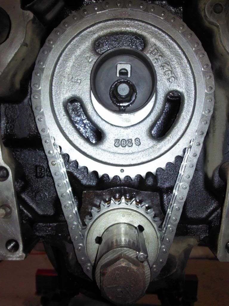 [/IMG]
Now, I have the engine at TDC with the timing marks still lined up but when i drop in the distributor the rotor isn't pointing at the spark plug tower on the cap. It's between two towers. Shouldn't it be pointing directly at one of the towers? The timing mark on the balancer is on the zero mark.
And now, drum roll please.................
[IMG]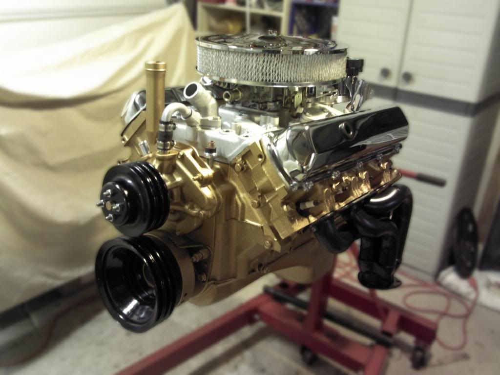 [/IMG]
[IMG]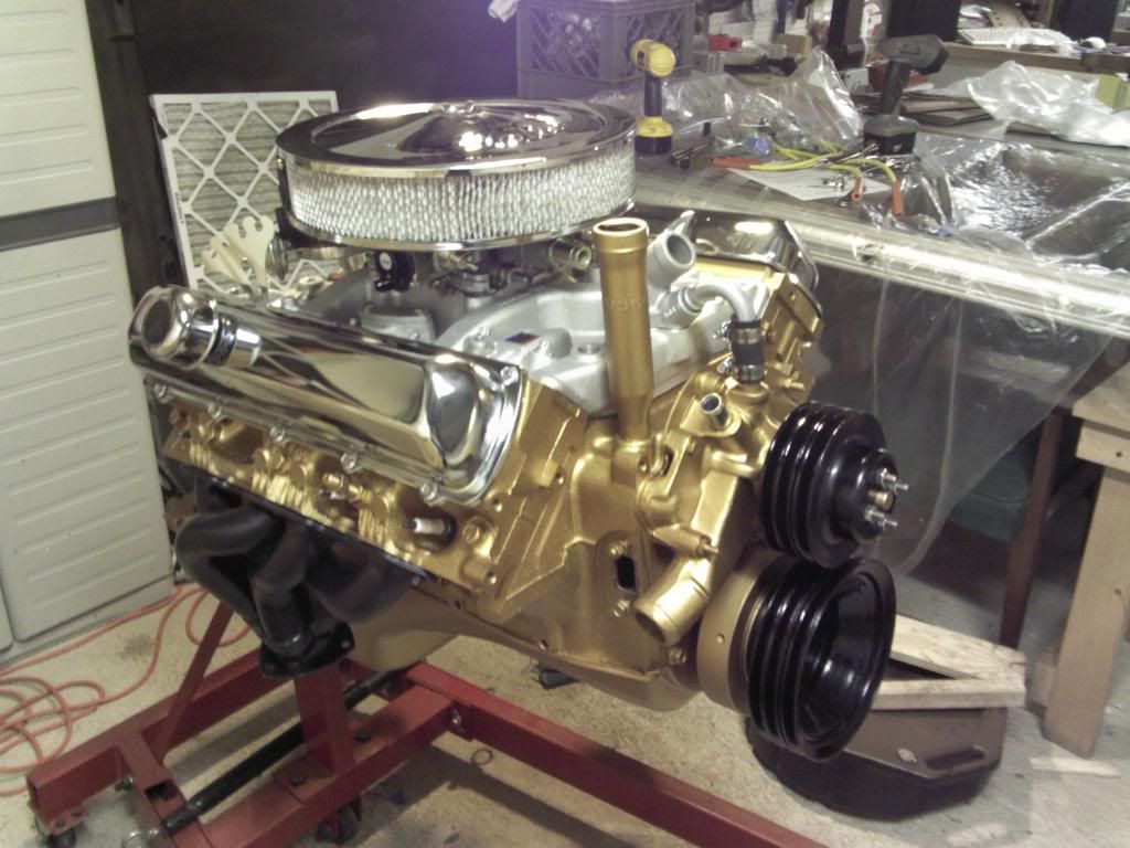 [/IMG]
So I'm wrapping up my engine refresh/build but I'm confused by the distributor installation. I'm swapping in an HEI and I'm doing it from scratch since I put in a new cam and timing set. I had the #1 cylider at TDC when I installed the timing set and thanks to Eric (mdchanic) I have a picture for verification:
[IMG]
 [/IMG]
Now, I have the engine at TDC with the timing marks still lined up but when i drop in the distributor the rotor isn't pointing at the spark plug tower on the cap. It's between two towers. Shouldn't it be pointing directly at one of the towers? The timing mark on the balancer is on the zero mark.
And now, drum roll please.................
[IMG]
 [/IMG]
[IMG]
 [/IMG]
 December 28th, 2013, 07:46 AM
#2
Connoisseur d'Junque
Join Date: Sep 2010
Location: The Hudson Valley
Posts: 21,183
It does look pretty. Now let's hope it runs. 
As for the distributor, switching to HEI is your choice, but you won't gain anything significant from it.
The rotor doesn't have to line up with anything specific when you stab it - it's just a convention to put the #1 wire in that location. As long as you start with the #1 wire wherever the rotor is pointing, with the engine at #1 compression TDC, and follow the firing order counterclockwise, and as long as the distributor can turn enough to adjust the timing, it will work fine.
By the way, your engine is lined up for #6 cylinder compression at TDC, not #1, so point your rotor to the #6 tower, or it won't start (confirm by removing plugs and rotating engine with finger in #1 or #6 spark plug hole).
- Eric
December 28th, 2013, 07:54 AM
#4
Registered User
Thread Starter
Join Date: Aug 2013
Location: Central Illinois
Posts: 3,900
It does look pretty. Now let's hope it runs.
By the way, your engine is lined up for #6 cylinder compression at TDC, not #1, so point your rotor to the #6 tower, or it won't start (confirm by removing plugs and rotating engine with finger in #1 or #6 spark plug hole).
- Eric
By the way, your engine is lined up for #6 cylinder compression at TDC, not #1, so point your rotor to the #6 tower, or it won't start (confirm by removing plugs and rotating engine with finger in #1 or #6 spark plug hole).
- Eric
Sorry Eric, you've lost me. Why am I on #6?
Thanks midrange, I'll give that a try.
December 28th, 2013, 08:03 AM
#5
Connoisseur d'Junque
Join Date: Sep 2010
Location: The Hudson Valley
Posts: 21,183
Topdeadcenteron1.jpg
Your timing dots are at 12:00 (crank) and 6:00 (cam).
That's #1 TDC compression for a Chebby, but for an Olds, #1 is at 12:00 (crank) and 12:00 (cam).
- Eric
Your timing dots are at 12:00 (crank) and 6:00 (cam).
That's #1 TDC compression for a Chebby, but for an Olds, #1 is at 12:00 (crank) and 12:00 (cam).
- Eric
December 28th, 2013, 08:09 AM
#6
Registered User

Join Date: Dec 2011
Posts: 7,286
Yes, at the time of sparking, the rotor should be pointing more or less at a cap tower. You can turn the dist'r housing, right? You have to rotate the housing to exactly where you want it to be.
Shirley, you realize that the spark is created when the points open, or when the pointy teeth align in the HEI or other pointless type system.
You can drop the unit in with the rotor a tooth away with respect to the cam gear, in order to gain a more favorable vacuum canister position on the housing, but the spark trigger to dist'r housing [to cap post] relationship is defined by the manufacturer of the distributor parts, and is not really changeable much, without machine work. So, with your timing marks at oh 0 to 10 BTDC on the balancer, turn your dist'r housing until you see that the point teeth are aligning between rotating shaft part and housing part [assuming points are not in use]. THEN see how close your rotor tip is to your favorite cap post.
On the cam timing marks, yeah, you need to grasp that basic facet of operation.
Imagine you turn the crank ONE revolution from that seen in the above photo.
Now you have the crank dot back at 12:00 and the cam dot at 12:00
THAT is the #1 cylinder firing position.
There are TWO crankshaft turns in a complete cycle, which is one camshaft turn.
1 8 4 3
6 5 7 2
When the cam dot is at 12:00, #1 is ready to fire.
One crank turn later, the cam dot is at 6:00, and #6 is ready to fire.
Other cylinders are every 90 crank degrees aka every 45 cam degrees.
If you are assembled already, and, frankly even if you can still see the cam timing dot... the CERTAIN way to ensure that you are at firing position for cylinder #1 is still the "finger in the spark plug hole" method, or the "observe the valve motion" method.
Last edited by Octania; December 29th, 2013 at 07:12 AM.
December 28th, 2013, 09:03 AM
#7
Registered User
Thread Starter
Join Date: Aug 2013
Location: Central Illinois
Posts: 3,900
Yup, sorry, still in Chebby mode I guess. I didn't realize Olds are different. With all the reading I did when installing the timing set I just assumed dot-to-dot meant compression on #1. And "assume" made an *** out of, not you, but me. 
Octania, I get the operation. Similar to a bicycle's gears. One complete crank turn = one half cam turn. And all the associated effects on the valves and distributor. But you lost me with the "pointy teeth". Are you talking about the spark gap between the rotor electrode and the associated tower electrode?
Octania, I get the operation. Similar to a bicycle's gears. One complete crank turn = one half cam turn. And all the associated effects on the valves and distributor. But you lost me with the "pointy teeth". Are you talking about the spark gap between the rotor electrode and the associated tower electrode?
December 28th, 2013, 10:54 AM
#8
Registered User
Thread Starter
Join Date: Aug 2013
Location: Central Illinois
Posts: 3,900
It's a 50k distributor if that makes a difference.
Last edited by Macadoo; December 28th, 2013 at 11:02 AM.
December 28th, 2013, 11:05 AM
#9
gap it to .060. that's the whole point of an hei. Being able to have a spark powerful enough to be more exposed thus a better and more efficient burn in the chamber. Don't worry about the hot or cold plug unless there is tuning issues but I doubt you will run what you have.
 December 28th, 2013, 01:53 PM
#10
Connoisseur d'Junque
Join Date: Sep 2010
Location: The Hudson Valley
Posts: 21,183
For spark plug gap, I'd go about 0.045"- 0.050", but 0.060" should be fine, too.
There's a lot of discussion about HEI plug gaps, but about the only definite information out there is:
- Eric
There's a lot of discussion about HEI plug gaps, but about the only definite information out there is:
- 0.080" is too big
- 0.035" is stock, and should work just fine
- Pretty much anything between there and 0.060" should be fine
- The larger the gap, the higher the voltage needed to jump it, and the higher quality your wires need to be, as some wires will be great at, say 30,000 volts, but will leak at 40,000 or 50,000 volts
- Eric
December 28th, 2013, 03:12 PM
#11
Registered User
Thread Starter
Join Date: Aug 2013
Location: Central Illinois
Posts: 3,900
I bought Accel 8mm. Supposed to be a good wire but I made the mistake of getting pre-cut. Is it okay if I wrap them around the carb a few times to take up the slack? ")
Thanks fellas. I appreciate it.
Thanks fellas. I appreciate it.

 December 28th, 2013, 04:12 PM
#13
Registered User
Thread Starter
Join Date: Aug 2013
Location: Central Illinois
Posts: 3,900
Yup, pretty much looks like mine. But are you running a double pumper under there?
Hey, I was looking at the HEI after I installed it and it looks like fitment is going to be tight. Like really tight. Looks okay in yours though.
Hey, I was looking at the HEI after I installed it and it looks like fitment is going to be tight. Like really tight. Looks okay in yours though.
December 28th, 2013, 04:17 PM
#14
Yeah I have a holley dp in there. If I install the dist in my "special" location lol I have enough room for 16 degrees initial which is what I run. By special I mean I have my feel good spot where I stab the dist. and if all is right usually fires up with in a few turns. If you look my vac. adv. is pegged to the wall. I don't run the vac. adv. so I guess it's pointless to even have it but the lock out thing is 13 bucks eff that lol.
December 28th, 2013, 04:23 PM
#15
This is bugging me so I have to lol. but in this pic I have all new fuel lines from the pump to the carb. I also hate chrome but some how I end up with this stuff lol. Not to hi jack the thread but my old pump to carb lines where scary. They worked but tech inspection always cringed at the track lol.

December 28th, 2013, 08:16 PM
#16
Registered User
Thread Starter
Join Date: Aug 2013
Location: Central Illinois
Posts: 3,900
I like chrome but like most things, it has to be done right. Not over the top. It's just too much when it's chrome everything, pulleys, accessories, core support, etc.
And for the record, as much as you help me out, I think you can hijack a thread here and there.
Did you have a question about your fuel lines? I think they look cool.
And for the record, as much as you help me out, I think you can hijack a thread here and there.
Did you have a question about your fuel lines? I think they look cool.
December 28th, 2013, 08:21 PM
#17
No questions. The last set up I had was just kinda hacked and I have since upgraded to "pro" status lol. I just redid it all . If you look at the one picture and the last one you can see the difference in the fuel lines. I was more or less pointing out I made some changes. Some members think im a bit of a hack but I make do until I can make it nice. Even when it's proper it's not "perfect" lol notice the combination of black an fittings and blue lol. I gathered enough stuff from swap meets and stuff my friend gave me to put those fuel lines together. as it was I have 60 bucks into it.
December 28th, 2013, 08:37 PM
#18
Registered User
Thread Starter
Join Date: Aug 2013
Location: Central Illinois
Posts: 3,900
Yeah I have a holley dp in there. If I install the dist in my "special" location lol I have enough room for 16 degrees initial which is what I run. By special I mean I have my feel good spot where I stab the dist. and if all is right usually fires up with in a few turns. If you look my vac. adv. is pegged to the wall. I don't run the vac. adv. so I guess it's pointless to even have it but the lock out thing is 13 bucks eff that lol.
December 28th, 2013, 08:40 PM
#19
Registered User
Thread Starter
Join Date: Aug 2013
Location: Central Illinois
Posts: 3,900
No questions. The last set up I had was just kinda hacked and I have since upgraded to "pro" status lol. I just redid it all . If you look at the one picture and the last one you can see the difference in the fuel lines. I was more or less pointing out I made some changes. Some members think im a bit of a hack but I make do until I can make it nice. Even when it's proper it's not "perfect" lol notice the combination of black an fittings and blue lol. I gathered enough stuff from swap meets and stuff my friend gave me to put those fuel lines together. as it was I have 60 bucks into it.
December 29th, 2013, 07:12 AM
#20
Connoisseur d'Junque
Join Date: Sep 2010
Location: The Hudson Valley
Posts: 21,183
As you have observed, the distributor turns half as fast as the crank, because each cylinder must go through two full revolutions to complete one cycle.
Because of this, crank degrees are double the number of distributor degrees.
The fun part is that distributor specifications are usually listed in distributor degrees, so that you can adjust the distributor on a distributor machine, and not in the crank degrees that we normally discuss.
So, to answer your question, if you rotate the distributor 15�, the timing at the crank (and the timing that you read off of the timing tab with your timing light) will change by 30�.
- Eric
December 29th, 2013, 07:44 AM
#21
Registered User
Join Date: Dec 2011
Posts: 7,286
There are two sections- low voltage, and high voltage production and distribution.
The coil makes the HV and must be triggered by the low voltage section. This is done either by opening and closing points, or by electronic voodoo using pointy teeth to let a magnet trigger transistors at exactly the right rotor position.
See the stationary [except for a small amount of motion controlled by the vacuum canister] pointy teeth which point inward at 13:20 of
NOT shown in that tutorial is the mating part of the rotor, with 8 outward pointing teeth which align with the inward pointing teeth every 45 dist'r degrees = every 90 crank degrees. These are a lot easier to see if the rotor is removed. Down there under the centrifugal advance mechanism is the magnet and pickup coil and the inward and outward pointing teeth that make the magic happen in the low voltage section.
Take a look at 1:55 & 8:54 of this tutorial
where a hand rendering and a dark view of an actual HEI are presented.
It would be highly useful to procure a junk/ scrap distributor, that no one cares about, and dismantle it [remove one pin and you are almost done]... and examine all the bits and pieces and how they move and work. There's only 6 or 8 pieces in there that do anything.
December 29th, 2013, 07:51 AM
#22
Connoisseur d'Junque
Join Date: Sep 2010
Location: The Hudson Valley
Posts: 21,183
Yeah. Hee hee.
This gives me the opening to say, "You want to "upgrade" to HEI because you 'didn't really want to mess with points and dwell,' and you don't even know how it works?!?
Doest thy homework or thou shalt have thy (chrome plated acorn) nuts busted.
- Eric
This gives me the opening to say, "You want to "upgrade" to HEI because you 'didn't really want to mess with points and dwell,' and you don't even know how it works?!?
Doest thy homework or thou shalt have thy (chrome plated acorn) nuts busted.
- Eric
December 29th, 2013, 07:05 PM
#23
Registered User
Thread Starter
Join Date: Aug 2013
Location: Central Illinois
Posts: 3,900
Okay Dad(s), I'll crack the books. And thanks for the vids and description. But cut me a little slack, will ya? I've done some significant book learnin' in the past couple of months, yeah? And a wee bit of hands on learnin' as well. Like how HEI may be lower maintenance but takes a whole bunch more space and, in my opinion, makes it harder to route the plug wires since you can't run them across the cap (because of the coil height).
December 29th, 2013, 07:21 PM
#24
Connoisseur d'Junque
Join Date: Sep 2010
Location: The Hudson Valley
Posts: 21,183
Hey, just funnin' ya.
It is interesting to note, though, how the Hall effect technology has improved over the years.
HEI needed those eight big pointy poles and that star shaped reluctor in order to work, but a modern system, like the Crane pickup, uses a single tiny sensor and picks up the magnetic variations directly from the octagonal points cam.
- Eric
December 29th, 2013, 07:28 PM
#25
Registered User
Join Date: Dec 2011
Posts: 7,286
Okay Dad(s), I'll crack the books. And thanks for the vids and description. But cut me a little slack, will ya? I've done some significant book learnin' in the past couple of months, yeah? And a wee bit of hands on learnin' as well. Like how HEI may be lower maintenance but takes a whole bunch more space and, in my opinion, makes it harder to route the plug wires since you can't run them across the cap (because of the coil height).
A junk one in hand that you can tear into is still invaluable.
There are other options to run the old small distributor with a pointless trigger, you know... built in rev limiter with adjustment pot, etc. I installed a Crane unit a while back, it was really easy and very effective.
Then there is the FACTORY pre-HEI pointless ignition system known as "UHV" for Ultra High Voltage.... I think it is a Capacitor Discharge type system. I have a few parts and a factory blueprint [and pdf made from that] of the wiring. Has a huge voodoo box the size of a damn xbox console that does what the module in your HEI does.
http://www.ebay.com/itm/1968-Olds-45...8a871b&vxp=mtr
http://www.ebay.com/itm/ORIGINAL-196...af626d&vxp=mtr
http://www.ebay.com/itm/68-Oldsmobil...f70184&vxp=mtr
December 29th, 2013, 07:46 PM
#26
Administrator
Join Date: Oct 2009
Location: Poteau, Ok
Posts: 40,555
I would like to suggest leaving the vacuum advance disconnected until you get your timing sorted out. Generally you need to run around 16-21 degrees of initial as most Hei's have around 17 degrees of mechanical advance. Depending on what vacuum can is on there and whether or not it's adjustable and adjusted correctly, it may throw your total timing over 50. That will lead to detonation at cruise.
I would also suggest installing your dist. after the engine is back in the bay to prevent a mishap.
I would also suggest installing your dist. after the engine is back in the bay to prevent a mishap.
December 29th, 2013, 07:57 PM
#27
Registered User
Thread Starter
Join Date: Aug 2013
Location: Central Illinois
Posts: 3,900
No offence taken here guys, just funnin' ya back
I'd read about the pointless triggers but I guess they sounded like a half-measure. I went with HEI because I'm familiar enough with them to be comfortable but I'm looking at it and wondering if it's going to fit between the engine and firewall.
I didn't know anyone had ever used a capacitor system. Sorta makes sense though, those tings can hold a lot of juice.
Thanks for the links but I think $2,750 is a little more than I want to spend on my distributor :P
Last edited by Macadoo; December 29th, 2013 at 08:01 PM.
December 29th, 2013, 08:01 PM
#28
Registered User
Thread Starter
Join Date: Aug 2013
Location: Central Illinois
Posts: 3,900
I would like to suggest leaving the vacuum advance disconnected until you get your timing sorted out. Generally you need to run around 16-21 degrees of initial as most Hei's have around 17 degrees of mechanical advance. Depending on what vacuum can is on there and whether or not it's adjustable and adjusted correctly, it may throw your total timing over 50. That will lead to detonation at cruise.
I would also suggest installing your dist. after the engine is back in the bay to prevent a mishap.
I would also suggest installing your dist. after the engine is back in the bay to prevent a mishap.
December 29th, 2013, 08:02 PM
#29
Connoisseur d'Junque
Join Date: Sep 2010
Location: The Hudson Valley
Posts: 21,183
The PO installed a Crane unit in the original distributor in the engine I'm running now, and, though I would have stuck with points had it not been there already, it's worked flawlessly.
- Eric
- Eric
December 29th, 2013, 08:13 PM
#30
Registered User
Thread Starter
Join Date: Aug 2013
Location: Central Illinois
Posts: 3,900
December 29th, 2013, 08:18 PM
#31
Connoisseur d'Junque
Join Date: Sep 2010
Location: The Hudson Valley
Posts: 21,183
December 29th, 2013, 08:26 PM
#32
Registered User
Thread Starter
Join Date: Aug 2013
Location: Central Illinois
Posts: 3,900
Well, that's it for the Cowboys this season. Guess there's always next year.
 December 29th, 2013, 08:39 PM
#34
Registered User
Join Date: Dec 2012
Location: Texas
Posts: 1,584
Man im glad i read this thread! It has been 40 years since i built an Olds motor. I too installed my timing gears crank 12, timing 6 oclock. Does this mean i installed it wrong? Does the cam gear need to be installed at 12:00 to begin with? Or is it installed correctly and then needs to be rotated from there to get TDC? Sorry to hyjack this thread i dont meant to but i need to know this too.
Thanks
Steve
Thanks
Steve
December 29th, 2013, 09:24 PM
#36
Registered User
Thread Starter
Join Date: Aug 2013
Location: Central Illinois
Posts: 3,900
Oh lord, I'm on the hot seat now.
Steve, if you did it wrong then I did too and we're both in for a world of hurt. However, Both the instructions that came with the timing set and the Chassis Service Manual said to install the gears dot-to-dot with the #1 cylinder at top dead center. Eric and I discussed this; without the cam in the motor there are no exhaust and compression strokes, just TDC. What I've gathered is that we installed the cam and crank gears on the exhaust stroke rather than compression so we're good to go.
OR we're just really screwed.
Fellas?
December 29th, 2013, 09:52 PM
#37
Registered User
Thread Starter
Join Date: Aug 2013
Location: Central Illinois
Posts: 3,900
Okay, I had to reread the Edelbrock instructions just to be sure and it does indeed say to install at 6 cam, 12crank. And it goes on to say that "on some engines it will be necessary to turn the crank one full turn to obtain TDC on the compression stroke in order to install the distributor."
But now here's why I am nervous; the instructions also say "do not re-install original oil slinger". But I did because I read on CO that it was necessary to keep the oil from leaking through the front seal. Is this going to be a problem?
But now here's why I am nervous; the instructions also say "do not re-install original oil slinger". But I did because I read on CO that it was necessary to keep the oil from leaking through the front seal. Is this going to be a problem?
December 30th, 2013, 04:13 AM
#38
Connoisseur d'Junque
Join Date: Sep 2010
Location: The Hudson Valley
Posts: 21,183
The Edelbrock instructions are clearly generic, and do not apply specifically to Oldsmobile engines.
You can put the cam gear at either 6 or 12 with the crank at TDC (keyway at 1:00), and it's all the same (think about it), but one way the distributor needs to point to the 6, the other way it needs to point to the 1, or the engine won't run (again, think about it).
For that matter, you can put the crank keyway at 7:00 and the cam at either 3:00 or 9:00, but there's no reason why you'd want to.
As for the oil slinger, once again the instructions are not referring to an Oldsmobile engine.
Of course you need to oil slinger. What are you going to do, leave it out?
Just goes to show - you can't believe everything you read.
- Eric
ps: if you have a link to the Edelbrock instructions, why not post it, so we can see what they were trying to say?
December 30th, 2013, 05:01 AM
#39
Registered User
Join Date: Feb 2011
Location: Denmark
Posts: 1,591
For spark plug gap, I'd go about 0.045"- 0.050", but 0.060" should be fine, too.
There's a lot of discussion about HEI plug gaps, but about the only definite information out there is:
- Eric
There's a lot of discussion about HEI plug gaps, but about the only definite information out there is:
- 0.080" is too big
- 0.035" is stock, and should work just fine
- Pretty much anything between there and 0.060" should be fine
- The larger the gap, the higher the voltage needed to jump it, and the higher quality your wires need to be, as some wires will be great at, say 30,000 volts, but will leak at 40,000 or 50,000 volts
- Eric
December 30th, 2013, 06:10 AM
#40
Connoisseur d'Junque
Join Date: Sep 2010
Location: The Hudson Valley
Posts: 21,183
There's always one wise guy.
There was a year or so in the mid-seventies when GM specified an 0.080" gap for some cars, but they abandoned it because it caused running problems (I believe that with only a few tens of thousands of miles the gap opened up too wide to work properly).
If it works for you, that's great, and I wi t argue about it, but my question would be, Does it work better than 0.050"?
- Eric


