When you click on links to various merchants on this site and make a purchase, this can result in this site earning a commission. Affiliate programs and affiliations include, but are not limited to, the eBay Partner Network.
Some background - Bought that car last Fall. Only 58K miles. Ran perfect, but smelled a little rich. Parked it December, didn't drive it again until last Saturday. Fired right up and ran great. Drove it all over the place with no issue - but did smell gas fumey when at stop lights.
Went to fire it up on Monday - Couldn't get it to start. Cranked fine and smelled like gas around the carb. Figured it was flooded, let it sit for a long time and still nothing.
Decided to go ahead and do a full tune up. Cap, rotor, coil pack, spark plugs, wires, and rebuilt the carburetor. I have the carb receipt from the previous owner. The carb is a rebuilt from Holley. They paid over $500 for it.
Found some issues with the carb. First off - It's warped terribly. I doubt this happened on this vehicle. I suspect Holley rebuilt it like this - Which is ridiculous. Second, there was no clip on the needle at all inside. Other than that, everything seemed OK. Cleaned everything real good and installed new filter, gaskets and o-rings. Mixture screws set to 3.5 turns out. Probably should have rebuilt a different carb (I have the original) - but I was already a bit into the rebuild by the time I noticed the warping, plus it was running previously. Also found a lot of cracked and damaged vacuum lines. Fixed/replaced all of them. Also the temp sensor had two wires that were worn through the insulation and touching. I corrected that.
Put it all back together and the engine fired right up. The hot idle was pretty low. I turned it up a bit to keep it from dying when put in gear. Let the motor warm up for quite a while. Put a dwell meter on the test lead and adjusted the idle air bleed screw on the carb. I could adjust it all the way in or out and the dwell meter did not respond to it at all. Adjustment screws on bottom of carb are impossible to get to on engine while running. Engine runs OK in park and will rev up, etc.. but if you put it in gear and give it gas, it just wants to fall on it's face and die.
I was curious if there were any check engine codes. Put a jumper wire in the OBD1 plug and I do not get a check engine light at all. The light never turns on. In fact - None of the lights on the right side of the dash turn on. So I don't know if it's just a bad bulb. The lights on the left side (battery light) comes on with the key forward.
Also - the EGR valve does not have a vacuum line going to it. Imagine that should at least cause some type of code.
My plan is to pick up an OBD1 reader and see what codes I can get and go from there. I really have no idea. Maybe the computer is not functioning at all? I checked all the relevant fuses and they look fine. I attached a couple photos of the engine bay, and one of the dash. It's the 6 lights to the right of the vents where I've never seen any of them illuminate.
Any ideas would be appreciated!
Thanks!
If you don't have a factory Chassis Service Manual for your car, stop right now. The CCC system is extremely sensitive to adjustment, and you MUST adjust it following the factory procedure as detailed in the manual. You cannot rebuild the carb, bolt it on, and expect it to run right. Adjustment requires either a scan tool or a dwell meter connected to the green test connector in front of the carb to let you watch the mixture control solenoid dwell time while you adjust the idle screws. If you did not do this, you will never get it to run right. Also, rebuilding the carb requires some specific gauge tools to set the MC solenoid adjustment height and the idle vent valve. Again, if you did not do this, you won't get it to run right.
The ECU used on the CCC system is pretty stupid. There are very few actual monitoring points. For example, the ECU only knows that the command was sent to the EGR valve. There is no way to monitor if the valve actually opens or closes (and thus no way to know if the vacuum hose is connected or not). OBD II systems have position monitors on the EGR valve pintle, for example. This OBD I system does not.
The bottom line is that the CCC system requires good, old fashioned troubleshooting techniques. There are dozens of failure modes that will cause driveability problems without setting a fault code. You must physically check hoses and wires, you must individually test components, and you must not assume that you can simply read codes and replace parts.
FYI you don't need a code reader. Simply jumper the A and B pins of the ALDL with the key in the RUN position and the computer will flash the Check Engine light to tell you if there are any stored codes. Don't expect anything since the light would be on all the time if there were stored codes. If the light doesn't flash 12-12-12 when you do this, you have a problem with the ALDL wiring or the computer or someone removed the bulb.
I appreciate your reply. I have done a decent amount of research on this carburetor (although I am far from a Quadrajet expert). Like I said in my post, I do have a dwell meter and had it hooked up correctly. Adjusting the idle air bleed screw had zero effect on the dwell reading. (stuck in open loop? - I'm not sure)
It is impossible to access the idle mixture screws on the bottom while the engine is running. I have seen flex screwdrivers for this, but I think even that would be near impossible with this cluttered engine bay.
My check engine light does not function, nor do any of the 6 indicator lamps on that panel. This is why I was thinking of getting a OBD1 code reader. Unless if there is an alternative route that doesn't involve removing the dash.
Basically if I can't sort this out fairly quickly my plan is to convert to non-CCC setup. IE - Edelbrock intake, carb, remove AIR pump, plug exhaust ports, HEI vaccum advance distributor, etc. I really don't feel like getting into a project that big (and expensive) right now, but at least it's a sure fired solution.
Last edited by 83olds98; May 13th, 2018 at 11:13 AM.
Yes a manual is critical to make these carbs run well, when they are dialed in they perform nicely.
Without a manual, I'd check for a bad canister purge valve, it is at the front of the carb. Pull the vacuum hoses, 3 or 4?, If fuel is in it replace it. Using a dwell meter on 6 cylinder scale try to adjust for 30 degrees. If no response to adjustments turn the mixture screws out one turn each and retest. If no result try turning one turn in from initial.
Clean and tighten the CCC ground at the intake manifold, unplug and clean the contacts at the ECM. IIRC the ECM is fused in the fuse box, 10 amp? Check it also.
Use a scan tool to confirm it's going into closed loop.
Does it reach full temp, good heat, thermostat correct at 195?
Good luck!!!
It is difficult but not impossible to reach the idle mixture screws, and it is mandatory that you adjust them to achieve the correct mixture control solenoid dwell. I do use one of the flexible tools. I've had four of these cars now. If you have any question about the state of the vacuum hoses, replace them all. Any small leak or improper connection will wreak havoc with the system.
I assume the engine was at full temp. I let it warm up for a good while. Started and stopped it a few times. I don't have a gauge to check the temperature though. All fuses in the panel look good. The dwell was near 30 on the 6CYL gauge - but again, did not respond at all to adjustment (only engine RPM caused the dwell to move) I have not checked the ECM itself or the ground wire. Also the canister purge valve. Maybe I'll take a quick peek at those tonight.
I guess the next plan is to order a flex screwdriver and OBD1 reader - Wait for those to arrive and see if I can get anywhere. Do you have any suggestions where I can find a proper shop manual? I have the Chilton book - Unfortunately it provides no information on rebuilding or adjusting.
Maybe in the mean time I could try to rebuild the original carb that is not warped if I can find proper bench specs to get going... but I think I've got ECM/sensor issues aside from carb problems.
If the ECU is in open loop mode (O2 sensor not warmed up) or if there is a fault that sends the ECU into limp home mode, the mixture control solenoid dwell is locked at 30 deg.
If the ECU is in open loop mode (O2 sensor not warmed up) or if there is a fault that sends the ECU into limp home mode, the mixture control solenoid dwell is locked at 30 deg.
Ah - That would make sense. I wanted to drive it down the rode a bit, then come back and check the dwell and see if it would respond to adjustment - but ran too crappy to do so. Really didn't feel like getting in a situation where I would need a tow. I had the car running for quite a bit, so my guess is it is in limp mode.
I checked the ECU.. Everything was plugged in. Figured it was at least worth checking in case some joker in the past would have unhooked it all.
To heat the O2 sensor, you have to run the engine above 2000 RPM for 2-3 minutes in Park. This is where a scan tool is helpful, as it will tell you if and when the ECU goes closed loop. If you really are not getting a Code 12 when you jumper the ALDL, that will lock the dwell at 30 also.
Yea, I am getting no check engine light at all (with ignition forward) - So either that panel of lights are dead (none of them light up) - Or there is some misc. electrical issue, or the bulb is dead.
I ran into a similar issue with my 307 powered 89 Cadillac after a rebuild and it turns out I misrouted a gasket during the rebuild that ended up pinning down the mixture control solenoid. If you turn on the ignition in diag mode and don't hear a clicking sound coming from the carb, make sure it's working and not pinned down. Best of luck.
Doing some more research I learned a few things. #1 I adjusted the lean stop screw incorrectly. I just tightened it down all the way. Seemed like it was on tight when I removed it. Had no idea it was adjustable. Should have figured it was with the spring.
Also - I guess there are really quite a few adjustments for these carbs. TPS, rich stop screw, lean stop screw, Idle air bleed valve, and the 2 mixture screws. Does anyone know where you can get the tools to adjust this stuff? I think a thin valve stem tool may work for the lean stop screw. I'll have to get one of those long flex screwdrivers for the mixture screws. I haven't taken the covers off the TPS or rich stop screw - so I'm not sure how they adjust.
Trying to decide if I want to get this one properly adjust on the car or just go ahead and do a fresh rebuild of the original carb. Does anyone know a book that will have all the factory bench specs (amount of turns on screws, etc) for these carbs? I see Haynes and other people have Quadrajet rebuild books - but don't want to order them if they do not contain that information.
Does anyone know a book that will have all the factory bench specs (amount of turns on screws, etc) for these carbs?
As pointed out back in Post #2, the factory Chassis Service Manual, specifically Chapter 6E. There are currently over a dozen on ebay with the least expensive one at $4.99. Be sure you get the one for the Cutlass and Delta 88 RWD cars and not the one for the FWD Ciera and Firenza. They look the same.
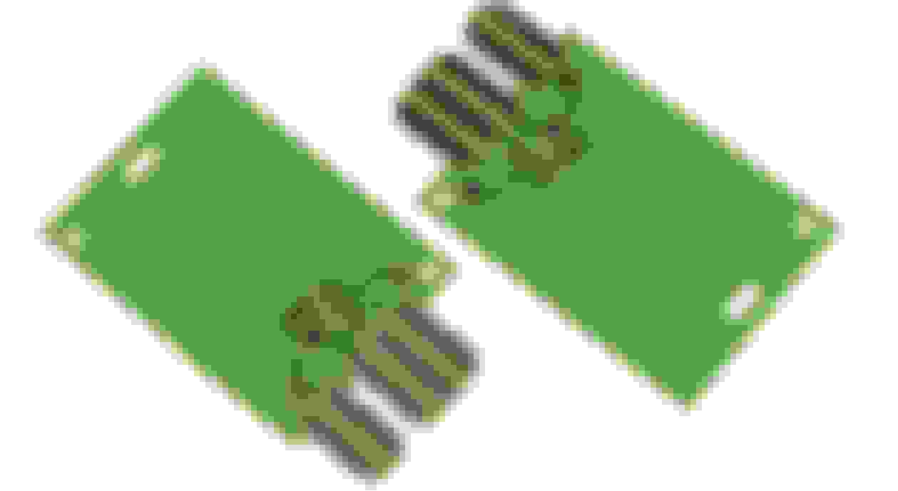
Back in the day when I was wrenching for a living I bought one of these Snap-On/BluePoint carb adjusting tools. Works great for getting to the mixture screws and you don't have to lean on a hot engine to make adjustments. There are a couple on ebay right now, that is where I found the picture. The complete set comes with all the right sockets to fit almost any carb. Flex shaft tool should be able to make adjustments too and lots cheaper.
So after spending all this money - I guess I'm pretty committed to making this work right with a CCC quadrajet. I'll give it another go with the original carb, All fresh new parts and bench adjustments. If I'm still struggling after that - The CCC system will definitely be gone.
If you aren't getting any lights in that cluster then chances are the sockets or bulbs are bad. My sockets were all bad, one of the legs on each one had broken off and wasn't making connections. Before you can make assumptions about what is or isn't working code-wise, check the light bulbs and sockets.
My experience is usually even if the carb adjustments are botched, it'll idle and be semi-driveable, it will just bog or be unable to handle extra loading, not die outright in gear. Putting it in gear and having it die is also a classic vacuum leak problem, usually from the PCV, which is easy enough to check while you wait for the shipment.
Definitely follow the procedures as outlined step by step in the factory book, it's the only way to get all of the different conditions accounted for. Having the right tools to read the sensors and signals is imperative, otherwise you're listening\feeling for clicks and that's not the easiest thing to do if you've never done it before.
I got the OBD1 reader in the mail. That was a waste of money. It doesn't even have lights on it! All it does is jump the two terminals. Comes with a book.. and that's it. Wow. Will see if I can return that.
Does anyone know how in the world to change the bulbs on this thing? I'm scared to death to start taking the dash apart. Or if there is another way access the check engine light voltage. I may be able to figure out the flashing by hooking up a voltmeter or test light to a particular wire.
Had a few minutes today so I fired it up with the same carb on it. Took the cap off the lean adjustment screw on top and loosened it. Didn't seem to effect how it ran at all. Turning it or the idle air bleed make no difference.
Something interesting then happened though - The check engine light came on! That was a shocker. I thought great, maybe now we'll get somewhere. Can't get codes though. Put a jumper wire in and tried the OBD1 reader, nothing. Light just stays on. So at this point I think it's safe to say there are some serious wiring/ECU issues. I think rebuilding the other carb and putting it on is probably a complete waste of time. My time is probably best spent at this point ripping out the CCC components.
The only thought is someone added a alarm system to this vehicle. Perhaps that could somehow be interfering? Kind of a mess of wires and module under the dash, so I'm not sure where I'd begin tearing that crap out.
In the CCC Manual I picked up - It shows flow charts for diagnosing check engine lights not coming on, or staying solid. I'll try to run through those today for fun to see if I can figure it out. Basically if it's not functioning correctly - it's a bad connection somewhere, or bad ECM.
Last edited by 83olds98; May 23rd, 2018 at 05:06 AM.
Looks like the book is telling me the "lamp driver" is likely bad. I've never heard of such a part before. Looked all over in all my manuals and can't find where it is located or how to test it, etc.. Ripped parts of the dash apart to try to find it, but I have no idea.
The "lamp driver" is probably just a transistor on the back of your instrument cluster. The computer output is � 5Volts. The lamp driver is activated by the 5V signal and switches the transistor to turn on the 12V light bulb in your dash. The problem could be a cold solder joint, a bad transistor, or a loose connection at any point in the circuit. It will take some dedication to find the problem but I would start with the instrument cluster. Check the connector to the cluster, all the traces on the back of it, and clean every connector you can with alcohol and a cotton swab.
The "lamp driver" is probably just a transistor on the back of your instrument cluster.
Not quite.
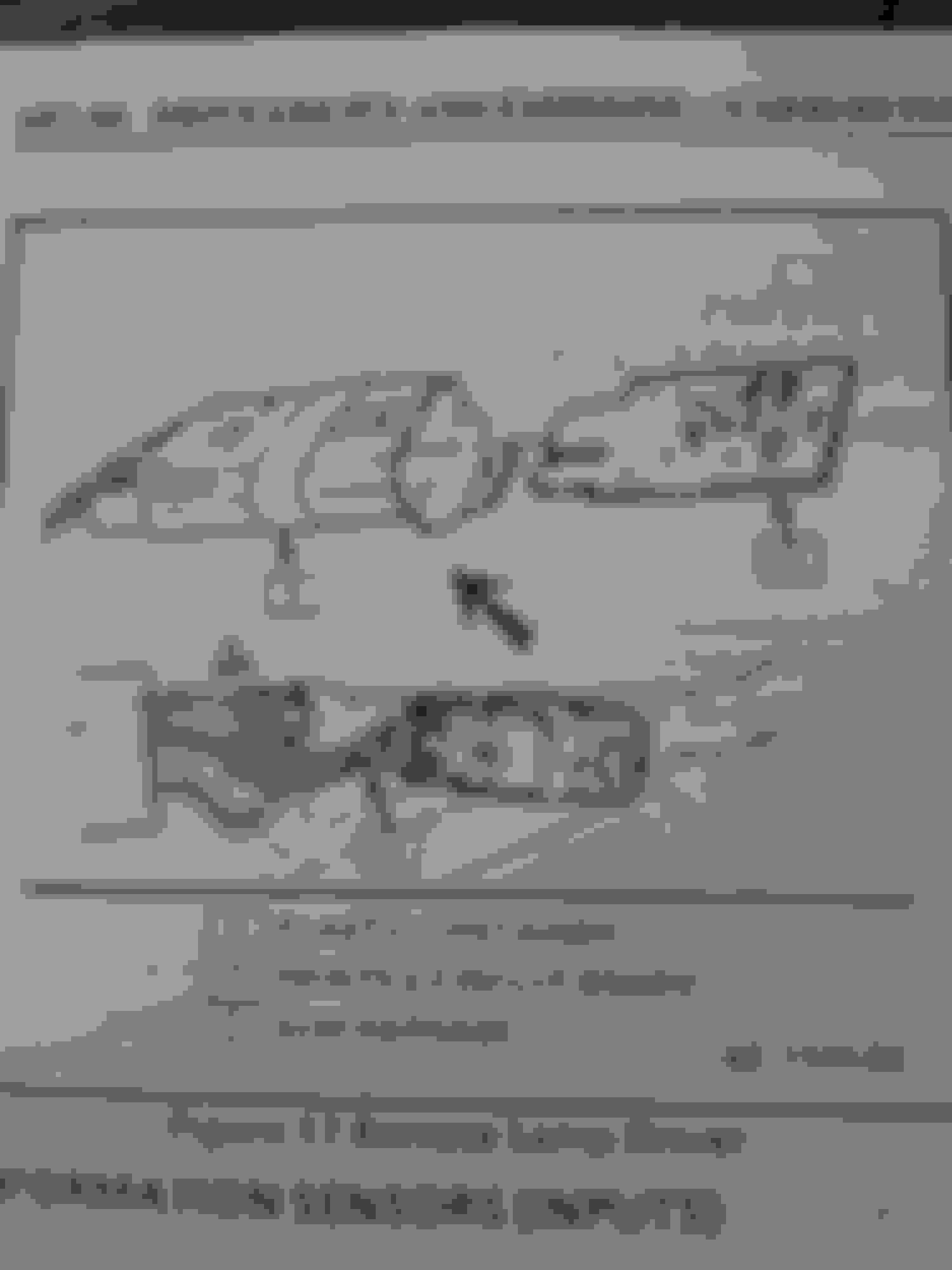
The lamp driver (alternately called both a "Remote Lamp Driver" in the CSM and a "Light Driver Module" in the Electrical Troubleshooting Manual) is completely described as to function and location in the CSM Chapter 6E1. The module is a small circuit board inserted into a connector and taped to the harness above the glove box. Pull out the glove box and you'll find the module. Functionally, it serves a couple of purposes. Yes, it includes a transistor driver to step the 5V ECU output up to 12V to operate the bulb, but it also has a "heartbeat" sensor circuit. If the ECU dies, the module senses this and powers the lamp. Were the lamp powered directly from the ECU, an ECU failure would likely not allow the lamp to illuminate.
I'm pretty sure the ECU is the large silver box with the wires coming from it under the glove box. I don't think there is anything inside the kick panel.
The lamp driver (alternately called both a "Remote Lamp Driver" in the CSM and a "Light Driver Module" in the Electrical Troubleshooting Manual) is completely described as to function and location in the CSM Chapter 6E1. The module is a small circuit board inserted into a connector and taped to the harness above the glove box. Pull out the glove box and you'll find the module. Functionally, it serves a couple of purposes. Yes, it includes a transistor driver to step the 5V ECU output up to 12V to operate the bulb, but it also has a "heartbeat" sensor circuit. If the ECU dies, the module senses this and powers the lamp. Were the lamp powered directly from the ECU, an ECU failure would likely not allow the lamp to illuminate.
Yea, I see that part in the book. My 98 does not have a lamp driver - or if it does, it is buried somewhere behind the instrument cluster, or somewhere else inaccessible. Or it does not look like the illustration they show.
I pulled out the ECM today and took it apart. Nothing obviously damaged on the board I can see.
Edit: I removed the kick panel and there are some wires going back there. A big block fuse block type connector with a bunch of wires going into it. No connector or anything that looks like the lamp driver illustrations.
Last edited by 83olds98; May 28th, 2018 at 02:07 PM.
Well - I'm pretty much out of ideas. I think I'm going to go ahead and eliminate all the CCC stuff. I would expect it to be a pretty straight forward process. My plan is to buy an aluminum intake, carb, distributor. I'll also need a different sized belt for where the air pump was.
Will I need anything for the lockup on the torque converter or any other issues I may run into?
The lamp driver (alternately called both a "Remote Lamp Driver" in the CSM and a "Light Driver Module" in the Electrical Troubleshooting Manual) is completely described as to function and location in the CSM Chapter 6E1. The module is a small circuit board inserted into a connector and taped to the harness above the glove box. Pull out the glove box and you'll find the module. Functionally, it serves a couple of purposes. Yes, it includes a transistor driver to step the 5V ECU output up to 12V to operate the bulb, but it also has a "heartbeat" sensor circuit. If the ECU dies, the module senses this and powers the lamp. Were the lamp powered directly from the ECU, an ECU failure would likely not allow the lamp to illuminate.
Hi Joe,
My Check Engine Light (CEL) wasn't working, grounded the ALDL pin 4 (yellow wire), then it lit. Disconnected the ECM and no CEL afterwards (service manual diagnosis steps). I think this is the heartbeat check you said above. Conclusion was the lamp driver is faulty.
So I took out the lamp driver circuit, it is the simplest looking thing I have ever seen.
Checked the 3 resistors and the diode, they are fine.
The capacitor is bad and so is the transistor. (Emitter-base shows no stable value, only the base-collector shows a value)
I can source a capacitor (B 271K is the number).
Looking for an equivalent transistor now.
The numbers show nothing on internet.
Looks like Motorola (M) symbol, 552 then 7594.
Last edited by kuseetha; August 9th, 2023 at 04:56 AM.
SUPPOSEDLY, there's Standard Motor Products RY-536 remote lamp driver. I've heard different stories about its fitment because the card has changed slightly over the years, but apparently it's a replacmenet for the lamp driver, 12040004 GM p/n. Just tossing that out there.
They look a little different than the old school ones and they sometimes call them brake light drivers, or relays, though. Updated circuits for sure. Around 70 bucks give or take. Kinda pricey IMO, but if you're not an electronics guru and can't fix your old one, getting an entirely new unit might be helpful.
Not sure if anyone's run into the same issue, but here's a troubleshooting guide for a non-flashing 12 code. It may be of use for someone.
This is some really helpful information!
Since this is available, now I can experiment with the old one and go for a new one if I ruin it any further. Will post any findings here.
Thank you.
Looking for an equivalent transistor now.
The numbers show nothing on internet.
Looks like Motorola (M) symbol, 552 then 7594.
R614
7594
EBC (for emitter/base/collector I assume?)
This was printed on someone's Monte Carlo lamp driver transistor mounted to the same p/n card you have. Not sure if this helps anything.
The good news is, I guess, is a new module card, even with the updated electronics, would still need to use a similar performing transistor? Or am I approaching this incorrectly? You could measure VBE or VBC voltages on the legs of the new transistor (I wouldn't even know where to start, though) to determine what older style transistor would be needed for fixing the old card, correct? Just thinking out loud.
Just as an FYI, Rockauto.com has the RY536 for $51 and change. I think they call it a relay or something. Use a discount code and get it for $49 and change.
Do the resistors and diode matter? Not 100% sure on the colors of the old style resistors, but I think I see a 10 Kohm 5%, brown/black/orange/gold (103) and a 16 Kohm 10%, brown/blue/orange/silver (163) and 360 ohm 5%, orange/blue/brown/gold (362) on the old and (new) cards, so initially it looks like a match there. Another picture showed what I believe is S104 on the new card's transistor, but that doesn't tell much.
If the diode is just used as a blocker, any general use diode will do? Or does it need to be a specific rating?
I'm not an electronics guy at all, but I've done some self studying on some of this stuff eons ago.
Thanks for diving into this. It would be great to know how to repair the originals on the cheap if need be. As in which component part numbers to purchase.
I of course understand the importance of repairing one easy and cheap, especially these obscure items.
Resistors and diodes do matter, quite not sure about the capacitor yet. But why would GM spend money on one if it isn't needed? 😁
Managed the replicate the circuit today.
The old transistor is clearly gone. Green LED indicates internal ground of the ECM.
Red LED indicates power going to the transistor. Yellow LED is the CEL.
Swapped the transistor but apparently the test transistor is faulty, it powers the CEL all times.
Since this setup is here, it's a matter of finding a suitable transistor now.
I will update the results once I come across one.
Last edited by kuseetha; August 11th, 2023 at 11:46 PM.
Local parts store had one of the SMP "brake lamp relays" RY536, so I talked them down to $40 and bought it. I forgot how small that little joker is. With my naked eyes, I can't read anything on the transistor and diode. But the capacitor is so small there's nothing readable on it, I don't think.
Anyway, as suspected, it has the 362, 163 and 103 resistors on it, and on the diode (biggest block on the card) shows F7 over F1 and then the cathode ID band is on the outboard end. I thought it was either F7 or F1, but not with both markings. WTF?
The Transistor has a "tG1" printed on it with a smaller, sideways "69" after that. Not sure if that helps with anything. I think I read something somewhere on a tG1 it was an NPN transistor.
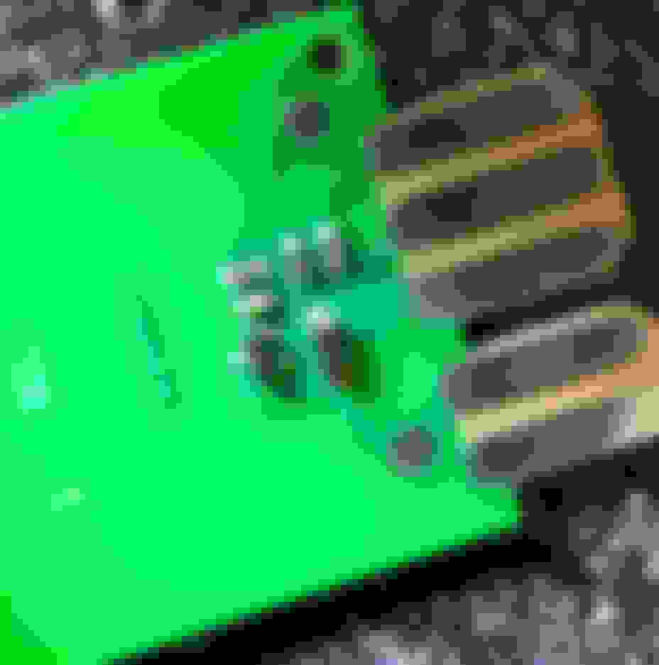
I managed to capture a magnified picture of the card with the transistor and junk on it. Hopefully this will help.
Seen another forum (electronics gurus) where someone was trying to find info on the same stuff. One of the members drew this potential circuit based off what he seen in some pictures of the old card. Apparently they guessed a little wrong on the resistor markings (poor pic) but covered that by saying if one of the rings on two of them were blue instead of what they guessed as green, they'd be 3.6 Kohm and 16 Kohm, so they were close. Also he just plugged in some numbers for the diode and transistor because they couldn't find those numbers either. They said it might be in-house markings for a generic part. Diode marked with 194 SC834, transistor marked with 345 7594, and capacitor marked with G 270K Y5S 100V.
Not sure if this is helpful or not. Found an SMD code sheet with these "tG1" listings on them.
Philips makes them. Looking at the data sheet, the PMST5551 should be tG3, not tG1, but not sure. Anyway, according to the data sheet, the "t" in the tG1 signifies it was made in Malasia. A "p" would signify made in Hong Kong. Nothing more.
It appears an appropriate replacement may be a 2N5551 npn (leaded equivalent)??? May be on to something here.
 May 13th, 2018, 10:14 AM