
307/350 swap, vacuum nightmare!! (77' rocket)
 December 7th, 2008, 12:45 PM
#81
ROCKETeer
Thread Starter
Join Date: Nov 2008
Location: Eastern Seaboard
Posts: 199
If your Caddy has Overdrive, you had a 200-4r 4 speed
If it's just P R N D 2 1 then it was a 200-C 3 speed
The 200-4r has a faster gearing than the th350, but the th350 is a better choice for you in my opinion.
Since the Caddy isn't going drag racing and having 3.73 or 4.11 gears in the rear end, you won't need the overdrive gear. Just remember that the th350 is a 3 speed trans and your gear selector won't read correctly anymore if you had the 4 speed trans before.
yeah the selector on my dash says P R N D 3 2 1, but no worries, i decided to move to a floor shifter

DSC01865.jpg
DSC01808.jpg


 December 11th, 2008, 11:49 PM
#85
ROCKETeer
Thread Starter
Join Date: Nov 2008
Location: Eastern Seaboard
Posts: 199
its weird to think that about a year ago, that thing was ready to blow someone up
 i decided to decommission it on the pretense people would think it was cool. so far so good
 March 11th, 2009, 04:22 PM
#88
ROCKETeer
Thread Starter
Join Date: Nov 2008
Location: Eastern Seaboard
Posts: 199
hey guys! ol' tony is back with some updates!
since its been getting nicer out here in connecticut, i started more head scratching...
i was able so far to start figuring out the exhaust...
DSC02155.jpg
DSC02161.jpg
DSC02163.jpg
DSC02162.jpg
i am also having a hard time finding a DETENT CABLE PIN if anyone and any good leads please hit me up!
DSC02159.jpg
DSC02158.jpg
DSC02160.jpg
i found a spacer for my carb, just have to get the correct bolts for it
DSC02021.jpg
i know its ugly, but i need it
March 11th, 2009, 04:58 PM
#90
Old(s) Fart
Join Date: Mar 2007
Location: Northern VA
Posts: 48,218
I apologize that I'm coming to this thread late.
I assume from your early posts that this 77 350 is going into a 1988 RWD Cutlass? Your first problem is that you need to understand the laws in Conn. Most states that require periodic emissions testing have two parts to that test, a tailpipe test AND a visual inspection. The reason for the visual inspection is that the tailpipe test is only a spot check of functionality. It is not practical to conduct annual (or biannual) testing that fully tests the functioning of all the emissions equipment. By conducting a spot test at one or two RPM conditions and verifying that all the factory equipement is hooked up, the assumption is that the car meets the emission requirements.
NOTE: THIS MEANS THAT THE EQUIPMENT FOR THE YEAR OF THE CAR MUST BE INSTALLED AND (AT LEAST APPEAR TO BE) FUNCTIONING.
The diagram you posted at the beginning of this thread was for a 1977 motor. If you hook this equipment up, it will NOT pass the visual inspection for a 1988 car. At least, it SHOULD NOT pass. The quality of emissions inspectors varies, as you might expect. The application of hundred dollar bills tends to help.
The good news is that most people cannot tell the difference between a 1977 350 and a 1988 307. If you install all the equipment from the 307, you will likely pass the visual inspection.
March 11th, 2009, 06:03 PM
#91
ROCKETeer
Thread Starter
Join Date: Nov 2008
Location: Eastern Seaboard
Posts: 199
March 11th, 2009, 06:10 PM
#92
ROCKETeer
Thread Starter
Join Date: Nov 2008
Location: Eastern Seaboard
Posts: 199
I apologize that I'm coming to this thread late.
I assume from your early posts that this 77 350 is going into a 1988 RWD Cutlass? Your first problem is that you need to understand the laws in Conn. Most states that require periodic emissions testing have two parts to that test, a tailpipe test AND a visual inspection. The reason for the visual inspection is that the tailpipe test is only a spot check of functionality. It is not practical to conduct annual (or biannual) testing that fully tests the functioning of all the emissions equipment. By conducting a spot test at one or two RPM conditions and verifying that all the factory equipement is hooked up, the assumption is that the car meets the emission requirements.
NOTE: THIS MEANS THAT THE EQUIPMENT FOR THE YEAR OF THE CAR MUST BE INSTALLED AND (AT LEAST APPEAR TO BE) FUNCTIONING.
The diagram you posted at the beginning of this thread was for a 1977 motor. If you hook this equipment up, it will NOT pass the visual inspection for a 1988 car. At least, it SHOULD NOT pass. The quality of emissions inspectors varies, as you might expect. The application of hundred dollar bills tends to help.
The good news is that most people cannot tell the difference between a 1977 350 and a 1988 307. If you install all the equipment from the 307, you will likely pass the visual inspection.
I assume from your early posts that this 77 350 is going into a 1988 RWD Cutlass? Your first problem is that you need to understand the laws in Conn. Most states that require periodic emissions testing have two parts to that test, a tailpipe test AND a visual inspection. The reason for the visual inspection is that the tailpipe test is only a spot check of functionality. It is not practical to conduct annual (or biannual) testing that fully tests the functioning of all the emissions equipment. By conducting a spot test at one or two RPM conditions and verifying that all the factory equipement is hooked up, the assumption is that the car meets the emission requirements.
NOTE: THIS MEANS THAT THE EQUIPMENT FOR THE YEAR OF THE CAR MUST BE INSTALLED AND (AT LEAST APPEAR TO BE) FUNCTIONING.
The diagram you posted at the beginning of this thread was for a 1977 motor. If you hook this equipment up, it will NOT pass the visual inspection for a 1988 car. At least, it SHOULD NOT pass. The quality of emissions inspectors varies, as you might expect. The application of hundred dollar bills tends to help.
The good news is that most people cannot tell the difference between a 1977 350 and a 1988 307. If you install all the equipment from the 307, you will likely pass the visual inspection.
no sir, its going into an 88 cadillac fleetwood brougham 4 door. i called up the state emissions clerk, and he said it didnt matter what was going back into the car, since its OBD1 and pre OBD all they do is a tail pipe test, i just have to tell them its a 350 instead of a 307. it has to have a cat and a EGR valve. no word yet on the smog pump, i dont have the original from the 77 motor, but i have the smog pump from the 88 motor, but the manifolds i have on the 77 do not accept those steel tubes that screw into them...
March 11th, 2009, 07:05 PM
#93
Old(s) Fart
Join Date: Mar 2007
Location: Northern VA
Posts: 48,218
no sir, its going into an 88 cadillac fleetwood brougham 4 door. i called up the state emissions clerk, and he said it didnt matter what was going back into the car, since its OBD1 and pre OBD all they do is a tail pipe test, i just have to tell them its a 350 instead of a 307. it has to have a cat and a EGR valve. no word yet on the smog pump, i dont have the original from the 77 motor, but i have the smog pump from the 88 motor, but the manifolds i have on the 77 do not accept those steel tubes that screw into them...
Originally Posted by CEP website
If your vehicle has any of these safety problems it will not be tested:
Excessive brake fluid leaks or any leaking fluids
Tires, wheels, or other unsafe conditions that make a vehicle unsafe to operate on the dynamometer including studded tires.
Emissions equipment tampering
Laws vary from state-to-state, but since tampering with factory installed equipment is against federal law, states with testing programs are not allowed to ignore this (and usually don't). The computerized test equipment spells out exactly what equipment is required based on the VIN of the car under test. Again, you are at the mercy of the test site inspector, who may or may not enforce this.
By the way, no Oldsmobile exhaust manifolds have ports for the A.I.R. tubes. The ports are machined directly into the heads above the exhaust ports.
March 12th, 2009, 04:56 AM
#94
ROCKETeer
Thread Starter
Join Date: Nov 2008
Location: Eastern Seaboard
Posts: 199
Well, all I can say is I hope you are successful. The state of Connecticut says otherwise on their Connecticut Emissions Program web site:
By the way, no Oldsmobile exhaust manifolds have ports for the A.I.R. tubes. The ports are machined directly into the heads above the exhaust ports.
By the way, no Oldsmobile exhaust manifolds have ports for the A.I.R. tubes. The ports are machined directly into the heads above the exhaust ports.
and as for the manifolds, you are absolutely correct, i forgot it was in the heads... but still, the heads on my rocket do not have the ports to accept the air tube...
this is the pump on the junk motor, i took pics of the heads when i realized this morning i was wrong about the air tubes, but you beat me before i could edit my post
DSC02167.jpg
DSC02166.jpg
DSC02165.jpg
this is the car
DSC02164.jpg
March 31st, 2009, 05:54 PM
#95
ROCKETeer
Thread Starter
Join Date: Nov 2008
Location: Eastern Seaboard
Posts: 199
i hope this is wired right
DSC02186.jpg
i just have to get a lower radiator hose, and tranny cooler lines, then i can fill all of the fluids and see if she runs good!
i have a question also,
my power steering pump pulley doesnt align correctly with the water pump, but i used all of the brackets and mounting points that the bracket will allow, the bracket itself is straight, but it seems like the pump is crooked in the bracket...
any ideas?
April 6th, 2009, 11:38 AM
#98
ROCKETeer
Thread Starter
Join Date: Nov 2008
Location: Eastern Seaboard
Posts: 199
im just moovin along here
DSC02190.jpg
DSC02191.jpg
DSC02192.jpg
DSC02193.jpg
DSC02194.jpg
DSC02195.jpg
DSC02196.jpg
DSC02190.jpg
DSC02191.jpg
DSC02192.jpg
DSC02193.jpg
DSC02194.jpg
DSC02195.jpg
DSC02196.jpg
April 6th, 2009, 12:23 PM
#99
Old(s) Fart
Join Date: Mar 2007
Location: Northern VA
Posts: 48,218
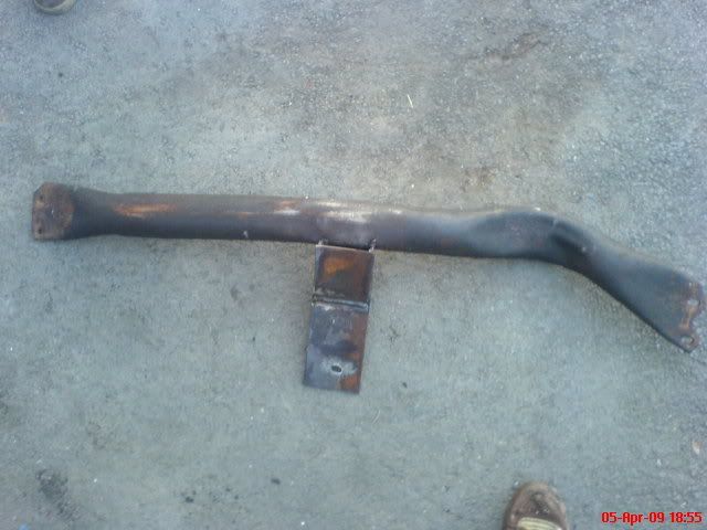
Nice welds, but pretty scary from a mechanical engineer's standpoint. You'll notice that the original trans mount bolt hole was in line with the mounting bolt holes at the ends of the crossmember. In that way, the trans imparts only vertical loads on the crossmember (and frame flanges), not any rotational loads. If you look at pretty much any factory crossmember, the trans mount will be in line with the crossmember mount bolts. What you have done is essentially put a pipe over the end of the wrench handle. This will cause a rotation in the crossmember and unintended loads in the frame rails. Couldn't you have just slid the crossmember forward and drilled new holes in the frame lower flange?
 April 6th, 2009, 09:10 PM
#100
ROCKETeer
Thread Starter
Join Date: Nov 2008
Location: Eastern Seaboard
Posts: 199
Nice welds, but pretty scary from a mechanical engineer's standpoint. You'll notice that the original trans mount bolt hole was in line with the mounting bolt holes at the ends of the crossmember. In that way, the trans imparts only vertical loads on the crossmember (and frame flanges), not any rotational loads. If you look at pretty much any factory crossmember, the trans mount will be in line with the crossmember mount bolts. What you have done is essentially put a pipe over the end of the wrench handle. This will cause a rotation in the crossmember and unintended loads in the frame rails. Couldn't you have just slid the crossmember forward and drilled new holes in the frame lower flange?
can you break that down a bit? that all sounds confusing to me... if i moved the member forward, there would be no room for the catylitic converter, and it wouldnt have solved my problem about lowering the trans so the driveshaft will clear the floor shifter mechanism...
April 7th, 2009, 08:38 AM
#101
Old(s) Fart
Join Date: Mar 2007
Location: Northern VA
Posts: 48,218
can you break that down a bit? that all sounds confusing to me... if i moved the member forward, there would be no room for the catylitic converter, and it wouldnt have solved my problem about lowering the trans so the driveshaft will clear the floor shifter mechanism...
Look at this photo:
DSC02190.jpg
Note that if you draw a straight line from one end to the other, it passes over the center hole for the trans mount.
April 7th, 2009, 09:51 AM
#102
Registered User
Join Date: Sep 2007
Location: Overton NV
Posts: 1,728
Just a thought off the cuff. It may not hurt to extend the ends of the mount forward, in order to absorb or counteract the torsional stresses added by extending the tab. In essence try to get your self an awkward W shape to bring everything back in line, without interfering with the cat, or shifter.
April 7th, 2009, 10:10 AM
#103
ROCKETeer
Thread Starter
Join Date: Nov 2008
Location: Eastern Seaboard
Posts: 199
okay i think i get what you guys are saying. how would you guys reccomend i go about making this work? i honestly thought this would be strong enough. my brother builds muscle cars and said that it should be fine as long as i dont beat on it ( we lowriders are low and slow ) it should be fine. this th350 i have has the shift kit in it that chirps second, and now i am worried when it shifts it will snafu my x member.
i really appreciate your insite guys!!!
i really appreciate your insite guys!!!
April 7th, 2009, 10:31 AM
#105
Registered User
Join Date: Sep 2007
Location: Overton NV
Posts: 1,728
It's not something I would have thought of either, I was just rewording Joes post, sort of. I would think a gusseted piece of flat stock 1/4" or so would be more than sufficient. just extend till you have a straight line across the trans tab and sides, add a bolt on either end and I would think you are covered.
April 7th, 2009, 10:47 AM
#106
Old(s) Fart
Join Date: Mar 2007
Location: Northern VA
Posts: 48,218
Just a thought off the cuff. It may not hurt to extend the ends of the mount forward, in order to absorb or counteract the torsional stresses added by extending the tab. In essence try to get your self an awkward W shape to bring everything back in line, without interfering with the cat, or shifter.
If you're talking about the tab for the trans, that doesn't help the problem. You'll still have the same amount of torsion in the mount and the same amount of bending load in the frame rails. The "W" design described above prevents the bending load in the frame rails by putting the loading point into the frame directly in line with the load application point.
The configuration you have currently will work - for a while. At some point the metal will fatigue and crack. Whether that happens in two hours or two decades requires a lot more math than I care to do at the moment...
 April 7th, 2009, 10:50 AM
#107
ROCKETeer
Thread Starter
Join Date: Nov 2008
Location: Eastern Seaboard
Posts: 199
:sigh: i wish i knew more about this while i still had the crossmember out. i dont even have a paint program to make a pic of what it should look like for refrence before i go taking this thing apart again and doing it up...
April 7th, 2009, 10:53 AM
#108
ROCKETeer
Thread Starter
Join Date: Nov 2008
Location: Eastern Seaboard
Posts: 199
I can't speak to your catalyst or shifter issues. From a structural standpoint, you should be able to draw a straight line between the trans mount location and the two ends of the crossmember. Anything else results in a twisting load in the crossmember and the frame that those parts were not designed to carry.
Look at this photo:
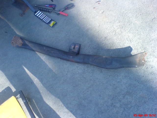
Note that if you draw a straight line from one end to the other, it passes over the center hole for the trans mount.
Look at this photo:
Note that if you draw a straight line from one end to the other, it passes over the center hole for the trans mount.
Just a thought off the cuff. It may not hurt to extend the ends of the mount forward, in order to absorb or counteract the torsional stresses added by extending the tab. In essence try to get your self an awkward W shape to bring everything back in line, without interfering with the cat, or shifter.
Yes, that is one solution that works. Of course, you still have the torsion in the crossmember - which translates to a bending load in the new extended tabs. The other problem is that you also still need to be able to get it in and out of the frame rails. Extending the tabs makes that more difficult.
If you're talking about the tab for the trans, that doesn't help the problem. You'll still have the same amount of torsion in the mount and the same amount of bending load in the frame rails. The "W" design described above prevents the bending load in the frame rails by putting the loading point into the frame directly in line with the load application point.
The configuration you have currently will work - for a while. At some point the metal will fatigue and crack. Whether that happens in two hours or two decades requires a lot more math than I care to do at the moment...
i really dont want this to get messed up. i know my topic isnt really all that olds related, sorry, but nobody else really seems to be as helpfull as you guys...
April 7th, 2009, 11:55 AM
#109
Registered User
Join Date: Sep 2007
Location: Overton NV
Posts: 1,728
I wasnt thinking about fitting it into the rails . Not looking at it and distracted[ can't find a freaking load that pays enough to start the freaking truck
 ] Done with rant...deep breath.....and.....sigh. OK. Not sure how else to get around the cat and the shift linkage. I wonder if a fellow could add some meat to the leading edge of the cross member and the mounting tabs? beef up the area for the tranny as well, but how much abuse is this going to see?
. Not looking at it and distracted[ can't find a freaking load that pays enough to start the freaking truck ] Done with rant...deep breath.....and.....sigh. OK. Not sure how else to get around the cat and the shift linkage. I wonder if a fellow could add some meat to the leading edge of the cross member and the mounting tabs? beef up the area for the tranny as well, but how much abuse is this going to see?
April 7th, 2009, 12:08 PM
#110
ROCKETeer
Thread Starter
Join Date: Nov 2008
Location: Eastern Seaboard
Posts: 199
I wasnt thinking about fitting it into the rails. Not looking at it and distracted[ can't find a freaking load that pays enough to start the freaking truck ] Done with rant...deep breath.....and.....sigh. OK. Not sure how else to get around the cat and the shift linkage. I wonder if a fellow could add some meat to the leading edge of the cross member and the mounting tabs? beef up the area for the tranny as well, but how much abuse is this going to see?
. Not looking at it and distracted[ can't find a freaking load that pays enough to start the freaking truck ] Done with rant...deep breath.....and.....sigh. OK. Not sure how else to get around the cat and the shift linkage. I wonder if a fellow could add some meat to the leading edge of the cross member and the mounting tabs? beef up the area for the tranny as well, but how much abuse is this going to see?well, the car rides like a cream puff, and although it will be doing highway and around town driving, i dont think im going to be beating on it. just driving to car shows and cruise nights and stuff. it was my daily driver for like 5 years, but i have a honda, so in the winter itll be stored...
April 7th, 2009, 12:16 PM
#112
ROCKETeer
Thread Starter
Join Date: Nov 2008
Location: Eastern Seaboard
Posts: 199
that was my original plan, leave it for now, and check on it, cadillac didnt really leave me many options here, but the main thing was i got the rocket in there and thats what counts. i think it will be okay, i might reinforce the tounge a bit more. i was originally going to use 1/4'' thick c channel, but i went with what i had.
but also on my topic. i still havent figured out my vacuum situation yet
but also on my topic. i still havent figured out my vacuum situation yet
April 7th, 2009, 06:58 PM
#113
Old(s) Fart
Join Date: Mar 2007
Location: Northern VA
Posts: 48,218
that was my original plan, leave it for now, and check on it, cadillac didnt really leave me many options here, but the main thing was i got the rocket in there and thats what counts. i think it will be okay, i might reinforce the tounge a bit more. i was originally going to use 1/4'' thick c channel, but i went with what i had.
April 7th, 2009, 10:21 PM
#114
ROCKETeer
Thread Starter
Join Date: Nov 2008
Location: Eastern Seaboard
Posts: 199
Refresh my memory (gimme a break - I turned 50 last year). Your whole crossmember problem is because the car came with a 200-4R and you swapped in a TH350? Have you considered just getting the crossmember from a 77-82 B-body car with the TH350 or TH200? Should bolt right in and clear the converter. If anything you might just need to drill holes in the frame lower flange to mount it.
April 8th, 2009, 10:21 AM
#115
Old(s) Fart
Join Date: Mar 2007
Location: Northern VA
Posts: 48,218
Your Cad is technically a D-body (renamed when the other C-body cars went FWD in 1985), but the only basic frame difference is the wheelbase. Note that I said 1977-1982 B-body. Your friend's 89 Caprice would have come with either a 700R4 or a 200-4R, neither of which used the crossmember I'm talking about.
April 15th, 2009, 08:25 PM
#117
ROCKETeer
Thread Starter
Join Date: Nov 2008
Location: Eastern Seaboard
Posts: 199
im really really close! if i can get the exhaust tubing i need ill have it running this friday. heres what i did today
i noticed i put the wrong bolt in to hold the hood on, and it dented my hood from underneath
DSC02212.jpg
DSC02214.jpg
does anyone know if this is right for the vacuum advance? i did all of the vac lines today and i was confused about these 2 ports on the back of my carb...
DSC02215.jpg
DSC02216.jpg
and i cant figure out what this fuel return line hooks up too...
DSC02218.jpg
also i figured out the powersteering pump, its not perfectly straight, but its better than it was before. i also put on the alternator.
i just need to bolt down the passenger side valve cover ( i ran out of screws :angry: ) find 2 plugs for the intake manifold, after i get my exhaust figured out i can bolt up the pass side exhaust manifold, fill up the tranny and radiator with fluid and i can start it
DSC02217.jpg
there just had been a lot of stupid little things getting in my way, there is a piece im missing that the vacuum system needs for the EGR valve to work properly, and i need to find a hot wire for the choke, and some other little stupid ****...
April 19th, 2009, 12:23 AM
#119
ROCKETeer
Thread Starter
Join Date: Nov 2008
Location: Eastern Seaboard
Posts: 199
DSC02225.jpg
these pictures should tell the story of what happened here...
DSC02227.jpg
DSC02228.jpg
DSC02229.jpg
DSC02230.jpg
DSC02231.jpg
DSC02232.jpg
DSC02233.jpg
DSC02234.jpg
DSC02235.jpg
started up the motor today, sounds good just gotta do the timing in the morning and im good to go
these pictures should tell the story of what happened here...
DSC02227.jpg
DSC02228.jpg
DSC02229.jpg
DSC02230.jpg
DSC02231.jpg
DSC02232.jpg
DSC02233.jpg
DSC02234.jpg
DSC02235.jpg
started up the motor today, sounds good
just gotta do the timing in the morning and im good to go


