When you click on links to various merchants on this site and make a purchase, this can result in this site earning a commission. Affiliate programs and affiliations include, but are not limited to, the eBay Partner Network.
For a daily driver go with .060" on the intake, and .080" on the exhaust. Make sure the guides are good to go, before you do the valve job. You might want to invest in a concentricity gauge so you can check your work.
Thanks for that info. These are my first heads that I have a chance of actually trying after I have ported them. I will be sure to let you know how it turns out. After all, you are my mentor :-)
the guides are all in good shape.
About correct shape of the seats... if gasoline cant penetrate past the valve in the seat, cant the seat be considered "even" enough?
Well I'm back to the grind stone. I took the summer off from porting to enjoy my race car. Thought I would show you guys a set of all out competition Mondello heads I have on my bench. 20151209_212556_zpsmbodpfcq.jpg 20151209_212526_zpsv5r4hkjf.jpg
A lot of work went into these heads. Unfortunately they are cracked in multiple places. The worst is between two valves which renders this head junk. I have heard of guys spray weld repairing these, but I have no experience with that. They belong to a fellow board member and they came off a boat. Deffinitely ran hard and put away wet. Pretty cool to analize the work done. Last year a set of these were on the flow bench and did OK. 280 CFM @ .7" lift intake and 197 CFM exhaust @ .7" lift. Pretty good considering the Edelbrock 60519 castings flow 253 CFM @ .6" intake/192 CFM @.6 " exhaust out of the box. These Mondo heads have some pushrod and head bolt holes sleeved - 20151209_212421_zpsywyyt7px.jpg 20151209_212351_zps67yr8rpv.jpg 20151209_212304_zpsx4cbloaq.jpg
Pretty interesting how the seat contact area dives straight into the bowl without showing 60/ 75/ 90 degree angles like Bill recomends in his book. I think he was refering to a street type port job, not all out competition. 20151209_212217_zpst57qp6w2.jpg
They also put a small notch in the top of the bronze guides. I've never seen this before and am curious if it was for oiling or what? 20151213_172009_zpsrfnuayhi.jpg
I've been working on some "A" castings and finished up with the intakes. I am going to have these flowed when done. I hope to come close to Joe's numbers without sleeving. May not be possible without raising the roof even further. I went up .185" on these pretty much the same as the "C" heads I did for Milan's 527 HP street thumper - 20151209_212121_zpsd9susiij.jpg
Look at that divet in the wall by the rocker bolt hole. This shot was taken before I did any work. Someone else already ground out the bumps but didn't do much else. I've never seen that divet before on C,G,J,GA, or any other SB head. I have another set of "A's" here with the same divet. 20151209_212110_zpsdebvyfmj.jpg 20151209_212038%20-%20Copy_zpsbbth33k4.jpg 20151120_195647_zpsqzq6bfe4.jpg
Hard to tell from the photos, but I've pulled the bowls back .125". 20151126_143616_zpsigdwfftp.jpg
The Mondello heads were also filled with Zinc alloy that has rattled loose. I have an idea about how to prevent that, just need to do some testing on my junk test head. If all goes well, I will reveal my idea and method next week. Of course it's experimental.
Hope you guys like this heavy metal BS, Dave - The freak
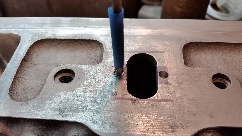
Here's my latest contribution to junk revival. I've seen it happen a couple times now where the Zink alloy, or Aluminum rattles loose in the heat riser over time. I tried something new here that was pretty simple, and easy to do. I drilled two holes .35" across from each other on the intake side by the heat riser port. I checked out a "G" head and the hole will go into the port but does not hit water. On this "A" head it does not go into the port. Then I take a thin Christmas tree carbide and open up the inner side of the hole to go into the port.
Then I put a piece of steel or dowl pin in there and weld it in place. 20151224_150812.jpg 20151224_151410.jpg
After welding, I grind the weld flush to the surface. It's important to have the pin recessed from the surface so the pour can go around it. In theory, I'm hoping this will act like an anchor point to prevent movement of the pour. 20151224_151639.jpg 20151224_154622.jpg 20151224_164607.jpg
This is all just research and development at this point. We really won't know if it works 'til my friend beats the crap out of this head for a couple years. He loves nitrous so much he may melt this **** out, who knows?
Hope you guys like this idea.
Merry Christmas, The Freak
Last edited by 67 Cutlass Freak; January 5th, 2016 at 07:17 PM.
When i was working in the aluminum head shop we had a machine / process system. Cleaned heads that leaked under pressure were "knocked up"
impregnated with resin. And they stopped leaking in the test bench fixture , leaked no more. Not sure if you / owner of the heads wants to take a gamble on this program / procedure???? the shop i worked has since closed
link above is for an example only
i have no affiliation
i have seen mondildo "port work" that was cut into the water jacket and then epoxied "stage 3" not much hope for that
Hey fellow Olds enthusiasts, I'm still here porting heads. Since last November I've done a set of Ford SB irons, A set of SB Chevys, A set of "A" castings that should be bad ***, and a set of Aluminum Edelbrocks for a Pontiac. I also wrote an article about porting Olds heads for Journey With Oldsmobile, the monthly publication that the Olds Club of America Publishes. Yeah it's like I have two full time jobs. Also over the past six weeks I have been helping my good friend Mike Ruth put together his Nostalgia Pro Stock Fairmont. Right now I'm porting a set of "E" castings for 507 olds (Brian Trick). This will be a hot street engine with minimal work - a good valve job, bowl blend, heat riser fill and basic removal of bumps, and just a little straightening of ports. I got a PM today from Oldsfaithful about some suggestions on exhaust port work so thought I would share here....
Oldsfaithful wrote: "Exhaust flow
Hey I see that you know your stuff when it comes to airflow and I am in need of some assistance. I am working on some smallblock #3 heads and cannot seem to get the flow past 155 @ .600 on the exhaust I have widened the port, did some bowl work and layed back the short turn radius. I would like to see upwards of 170-180. Any advice would be greatly appreciated."
Your goals are not too lofty. BB & SB exhaust ports are almost identical. Let me see if I can help you in order of what I feel will yield the most gains -
1) Oversized valve such as 1.71" with a good valve job. Make sure there's a nice 75 degree cut below the 60.
2) Bowl work, don't go too crazy on the exhaust. Just make sure you have a nice transition below the valve job. Also square off the edges of the short side radius.
3) Raise the roof .150" but also realize that you may have to open up your header flange. Cary a straight line path all the way to the base of the guide.
4) Remove the AIR bumps in the port, and tear drop the guide. I don't widen the exhaust port too much, but I will straighten out the walls some to give a straight shot. The exhaust port on our heads pretty much sucks and there's no way around that. Be careful around the head bolt holes. There's not much metal there.
*** DON'T TOUCH THE FLOOR. There's no flow there.
Here's what I was working on tonight. Just needs a little more work -
Very good article. What he is testing is a well developed port with a matching intake manifold to feel that "third pulse". That third pulse will happen at a tuned moment depending on your intake/head combination. That in and of itself should be what a head porter strives for.......at the right moment of course depending on your camshaft and specific RPM range you are shooting for.
CSA is the key. You want that pulse to happen just as the intake valve is opening for the ram air affect. I look at volumetric efficiency as well as flow coefficient for the valve size you are testing.
For what its worth, I have been going toe to toe with a Mopar guy at work. He has a 2.19 valve and I have a 2.07 valve. With my J head, I barely beat him with flow so far, but I absolutely whoop his *** with flow coefficient.
67 Cutlass Freak I dont think I wanna mess with porting the exhaust nor do I think I will hit 200 cfm. How much will you charge me to do the exhaust side on #3 smallblock heads?
Oldsfaithful, right now I have three sets of heads lined up on my bench to port. Each set is custom tailored to meet the needs of each engine they will be bolted to. Each set takes me 6-8 weeks to complete. I have never been asked to do just the exhaust ports. I always do the valve job in steps while porting. I do have a price sheet I could send you with my head service options. I would like to know more details about what work has already been done, what valves do you have, what are the short block details, and what power level are you hoping to achieve?
Last edited by 67 Cutlass Freak; February 25th, 2016 at 07:23 PM.
I will send you my current price sheet. Right now I am charging $20 per hour to port heads. That price may go up, so I'd rather not post a set price sheet here. Generally I don't like to port heads that have already been messed with. I'm not saying you did a bad job but if material was removed from an area that it should not have been, you can't just glue the metal shavings back on. I would like to help you. I will include my phone number in the PM.
Give me a call and we can discuss your build, Dave - The Freak
Oh those look great Dave! I need to get my porting tools and starting practicing on my J heads. Are those pics from Brian's E heads?
Yes they are Brian Trick's heads. I am real interested in how these will flow when I'm done. They had some minor issues when I got them. Someone epoxied the seats in. I have never heard of anyone doing that. I was worried they were trying to seal a leak or something. They passed the pressure test so all is good. They also had a problem with guide material by the seat pocket cracking and breaking off so I took care of that. The valve job was very lacking. My good friend Don (80 Rocket) did an outstanding valve job at T&T machine shop in Gurnee, IL. I usually do the valve job myself, but I really wanted the best possible job done on these heads. I can not hold the same tolerences using stones that these guys can do with a Serte. They turned out great. Now I'm close to 3/4 done with these heads. We are taking a little different aproach on these. They are not a max effort but a simple bowl blend, removal of bumps, some port straightening but no raised roof. I'm sure I will have close to fifty hours into these heads when they are done. Don has really been helping me with flow bench data to help me maximize my efforts. You should pick his brain about those "J" heads. He has some pretty amazing flow numbers coming from a set he's been messing with.
Is it safe to grind 0.06" to 0.1" from the valve spring place? I have a LS springs, thinking about assemblem them to my C-heads, but they are 0.06"-0.1" too long.
Is it safe to grind 0.06" to 0.1" from the valve spring place? I have a LS springs, thinking about assemblem them to my C-heads, but they are 0.06"-0.1" too long.
NO IT IS NOT ADVISABLE. The spring pocket area is pretty thin already. Thinner on some castings than others. Either purchase longer valves or the correct springs.
Dave i want to thank you for the info,pictures,and for being a good guy period. I have been working on a set of E heads porting them. I would never tried this with out your info and help. I did not need to do a port job on these heads i did it because i was bored with not having job and this interested me and i had a set of E heads just doing nothing. I have two set of e brocks on two of my engines. I have a set of C heads that were ported by someone else. You are a asset to this site or any site.Thank you for all you do.Neeley
I got the heat riser plugs welded then i welded the cross over divider with a mig. The plugs in the heat riser are about.200 in the hole. I used scrap lawn more blade for material for the cross over. Cut pieces off with a plasma cutter.
I got the heat riser plugs welded then i welded the cross over divider with a mig. The plugs in the heat riser are about.200 in the hole. I used scrap lawn more blade for material for the cross over. Cut pieces off with a plasma cutter.
I cleaned the hell out of the area where the hole is and set the custom fit plug.200 in the hole glowed red with heat turn up on the mig. Had minor pin holes i just waited and touched them up with more welds after i smoothed them first to see how deep the holes were then re-smoothed after touch up. i can text pics to you. send me info in a pm. I used lawn mower blade to fab cross over divider! I clamped in place put tack weld on each end. Then i welded both sides. Then i ground down to match surface. This was easy to do. Spent more time fabbing plugs and crossover parts than any thing else. Everything needs to be very very clean with good penetration.
Sorry I haven't been on here for a while guys. I've been real busy. Last time I posted I was knee deep in aluminum shavings. I actually had a chance to revisit my "C" casting heads that were done twenty five years ago. Initially I was just going to clean them up, inspect them, have them flow tested, and then bolt them back on. I found a couple things that I didn't care for so much. First problem was the valve to guide clearance was too loose, so I had new bronze guides installed. Upon close inspection, I found what looked like a tiny hair line crack on one of the intake passage walls. I had ported just a little too far into one of the push rod holes. So I decided to open up all the intake runners as wide as I could go right into the push rod holes. I also raised the roof another .150". I also decided to go with a bigger 2.12" intake valve this forced me to also put new hardened exhaust seats in to allow for proper valve face to seat contact area. I also wanted to have the best possible valve job so Don @ T&T Racing Engines machine shop helped me with all my needs. He even went in with the 75 degree cutter deeper than normal to show me how far back the bowl should be blended. He did tell me boring the holes for the sleeves should have been done before I cut right into them with the die grinder. Needless to say it was challenging for him. I also had them mill .050" off the head surface. Here's some photos - 20160723_215830.jpg 20160723_215822.jpg 20160723_215840.jpg 20160723_215904.jpg 20160723_220005.jpg 20160723_220010.jpg 20160723_224851.jpg 20160723_224904.jpg
The roof of the intake on my Victor manifold also had to be raised up to match the heads. I also went with the full rough up procedure on the plenum and runners. 20160724_210729.jpg 20160724_210748.jpg
I also changed the cam and rear slicks on my car before I took it down the track over the summer. Along with painting it and putting the trim back on. I was really hoping the engine mods would get me down to 10.50, but that was not the case. I wish I had done back to back testing with just the head mods and nothing else. The car was a consistent 10.80 all summer even in the heat. I think the tire size hurt me. I went from a 32" tall radial to a 33" tall biased ply. My 60' times were almost a tenth slower, but through the traps I was @ 125. About 1.5 MPH quicker, but 300 RPM lower than last year. Don thinks I may have ported the heads a little too far, and the lower end torque is suffering. The heads are better suited for higher RPM application, but my converter, and bottom end are not. I'm going to get new slicks for next year, and work on improving my 60' times. Car really is leaving like a slug. I'm just going to hit every bracket race I can, hone my driving skills, and enjoy the car for what it is. Some day I'll build a race engine that can spin up a little higher.
I thought I would post up some flow sheets that were done as comparison with my "C" heads. I realize the colored graph on the first page is really hard to tell what's going on. The colors are too similar and the lines are just a little too close. Never the less, the results are pretty interesting. The other heads that are on here were all flowed on the same bench but not the same day. When looking at these numbers keep in mind every flow bench is only one tool we use to help us design a better functioning head. We've already established the flow numbers are not the most important thing to go after when designing a port. Big thanks again to 80Rocket for all his efforts in trying to advance our understanding of the science behind our heads. C%20heads%20flow%201%20001.jpg
What you are seeing here is an overlay of 4 flow test sessions.
bb-'c' 002 are my heads after the last stage of porting
procomp 003 are a set of Procomps with minor bowl work/ quality valve job
bb003f is a 'J' casting with some pretty significant port work by Don
bb-'c' are my heads with previous port work
edelbrock performer RPM heads out of the box c%20heads%20flow%20comparison%20001.jpg
It's a lot easier to look at the numbers for comparison. I'll share some of my thought, first the additional work I did to my heads really did not flow much better than before. Really not worth the extra twenty hours that I put into porting them not to mention the machine shop and parts cost. By increasing the port runner volume I killed the velocity. Really better suited for a higher RPM engine. The pocket ported Pro Comps look really good up until .450 lift then they took a dive. Don's "J" port job surpassed the peak out of the box Edelbrock heads. Very impressive. The stock E-brock heads took a dive right after .400 lift and never really went that high at all. The exhaust ports flowed so close on all these heads it's really not even worth talking about.
Soon we will flow my experimental head with 4 radically different intake ports.
Why wasn't the exhaust done on the J's? I know it is similar to the awful 4A heads exhaust side, just curious how far out it would be.
I didn't work on the exhaust yet.
The stock J exhaust flowed 126cfm @ .400 and 131cfm @ .500.
I don't pay much attention to exhaust flow numbers however. They can be highly misleading since a flow bench in no way, shape, or form, can simulate the exhaust cycle with any degree of accuracy.........but, it is definitely safe to say the J head is really bad on exhaust flow.
It lost flow at .050 and .100, but picked up substantially after that. I changed from a tulip to a flat back valve as well as worked the area a little more right before the bowl entrance.
Wow...100,000 views on this thread. Thanks for helping me keep it alive to all who have followed along and participated. I will try to continue to bring data and techniques to our community. I am also working on an advanced porting article for the "Journey with Oldsmobile" magazine. So keep an eye out for it in an upcoming issue.
Thanks for your support guys, Dave - The Freak
What is wet flow head porting?
When doing wet flow we are interested in where the flow is and what it is doing. Most people don�t ask for wet flow testing because of the extra expense, this type of porting could be as high as $1000 back in the day. When doing advanced porting of heads which is beyond the normal throat and bowl work one has to rely on experience and this opens up the chance of turning a great port job into just a good port job. A good craftsman will use all the tools available to them to ensure this chance becomes skill. I started doing wet flow porting 30 years ago which is before Mondello &Knowlton started doing it. To do wet flow porting you have to either duplicate the intake runner or use the intake your going to use and a piston in a cylinder. You can make the intake runner out of a material that can handle the flow and vacuum, I use very stiff cardboard, bristle board, or even very thin wood panels. For the cylinder I have used clear plastic cylinders and PVC pipe that is or is close to the actual cylinder bore. For the piston I like to use thin plywood. Also the plate (piston) has to be placed at the 75% point of the stroke, which is where the air reaches max speed and glue it in place. So for a 4� stroke the piston would be 3� away from the head. I have a large 2 speed shop-vac that I use for the air flow, remember we are NOT measuring the amount of air flow but where the flow is or isn�t and what it is doing. I use low speed for street heads and high speed for high revving engines but, a single speed will work just fine. I cut a hole in the piston plate and place the hose end in it and make it flush with the plate. Next I use a height gauge or evenneedle nose vice-grips to hold the valve open at the height that I got max airflow. I then fire up the vacuum and spray fluorescent orange paint into theintake runner I made. With time a person will learn how much paint to spraywithout making paint runs. Also the heads need to be placed at the same angle asif it was on the block. The results will amaze you. Note: I was working on these heads and was in a big rush to get them done and thought I could skip afew steps, big mistake. Anyway it was just before my accident 22 years ago and had to stop, it�s only now that I can get back to them. Because I couldn�t race anymore, my legs didn�t want to work very well, I worked on everybody else�s engines and cars. But with time and a special back brace I can drive again, so let�s give�er.
Air like water or electrical current will always take the path of least resistance. So what does wet flow show you? Well it will show you where the air is slamming into an area or passing over it completely. It will also show you just how much swirl the ports have. It can show you just how much effect different intakes have on air flow, for example, stock or performer style intakes favour the roof of a port whereas a sheet metal tunnel ram favours the floor of a port and a Victor style favours the center of the port. Some porters fill/build up the bottom/floor of the port, this forces the air flow to flow more to the roof of the port and a raised floor can provide a better entry into the valve seat. Because of what the wet flow shows, I�m totally against building up the floor of the port until I wet flow with the intake mounted to the head and see where the air flow is. I�m also against filling the floor because the wet flow shows that it is being used, not much tell you but, it is being used. I usually just leave the floor alone unless I need to force the air flow upward. The benefits of a lower floor won�t show up on a flow bench because flow benches have a constant air flow unlike an engine where the valves open and close and create pulse waves. I would love to make a flow bench that uses the cam chosen to open and close the valves and then measure air flow. Intake runner length tuning works and I have found that Olds heads and intakes are almost a natural length. There�s a reason the Olds narrow dog-leg ports flow so much and the wet flow shows you how to take advantage of it. I have to admit that making a copy of the intake manifold runners and not have them collapse is a PITA but, it�s worth it. The porting on these heads are almost identical to Dave�s porting, so Dave please take a good look at these pictures, maybe you can get some good ideas, I�ll pass mine onto you. If there is enough interest I�ll redo the pictures and include stock 23 degree World Products SR heads for comparison. To me Olds heads have 2 port layouts when it comes to porting. In the pictures below the flow either originates from the left or from the right. Also when porting you either remove material to create a path for air flow or you reshape material to force the flow to go where you want it and that�s all porting really is.
Don�t talk down Olds heads:
It really irks me when people start talking down Olds heads and comparing them to other makes. I don�t think these people have ever worked on heads or engines or even seen other makes. When we were running the sbc 411 we had 18 degree Pontiac heads not the Chevy 23 degree heads. We used these heads because they made more power than the 23 degree ones and the Pontiac heads made more power because the 18 degree angle allowed the air flow to use more of the valve opening. So the 6 degree Olds heads allow the air flow to use even more of the valve opening. I have to get some pictures showing the wet flow of 23 degree and 6 degree heads so I can show the difference. Dart has a new 9 degree head, funny how people say the Olds 6 degree heads are no good but, the head manufacturers are slowly coming down to the Olds 6 degree heads, their only 3 degrees away now. They say a picture is worth a thousand words and these are no different, sorry the pictures are of old work but I�ll get some newer ones later on. These heads are for myself and should put me in the low 12�s. These �G� heads flow a max of 232cfm@28� stock with 2� intake valves and I�m hoping for at least 275cfm when I�m done. I�ll be using these heads until I can afford Wenzler/Rocket Racing ones. Another thing is that Olds heads are a high swirl (actually too much swirl) semi-hemi design and resist detonation/knock a lot better than the other guy�s wedge heads and a hell of alot better than true hemi head designs.
In the pictures what looks like shiny rust is actually paint that has evaporated, fell off, or changed somehow for somereason, I need to reflow these heads (wet) as I port. I lost all my intake runners and cylinders during our move to here, so I�ll have to remake them as I need them. In the picture below, areas AS, BS, CS, and DS show the area of no flow, this can be both good and bad. Both CS & DS show that the flow is not sticking to the surface because of the boundary layer and port shape. But AS & BS are areas of dead air because the flow has to go around the valve guide. This dead air is a loss of flow, BS is an area of high speed, high pressure air that is squeezed and forced upward. AS is an area of low pressure;however the 2 streams recombine at F-END. This AS BS area is very turbulent air that forms a bubble and creates a restriction; also notice how wide the dead air bubble is at F-End? You can also see how the paint/air slams into the valve guide and the valve bowl surface just to the right of DS. This is not good, what I want to see here is just a slight coating of paint like CP in the picture below. Sometimes however; you just have to make the best of things like in the 2nd picture. The total flow area is from F-Start to F-End to DS, so just over half the valve circumference is being used for flow, you won�t get this much with 23 degree heads. ES is where the main air flow is and continues on to GS.The problem here is that the flow at GS is to close to the head surface and is aimed at the cylinder wall. On the cylinder wall you could see paint that was just 1.5� away from the head and it went 3/4 the way around the cylinder. This high swirl is good for well mixing of the fuel/air, this gives good low rpm torque, better gas mileage, and helps to reduce knock. But, this kind of swirl is bad for Hp because it is washing away the oil from the cylinder wall and does not mix the lower cylinder area. You can see some flow along the edge of the valve seat, this is the area that really needs to be improve by working on the short turn radius (CS to F-Start the black area) also known as the port floor area that turns into the valve seat. The edge of the combustion chamber ES to DS needs to be ground back a bit to help unshroud the valve. Now if your not sure if tear dropping the valve guide doesn�t matter,then compare the next 2 pictures below.
This has a ported intake but, is not finished i.e. combustion chamber, exhaust, touch ups, and balancing. I chose this picture below because it has a lot of interesting things happening and it also has it�s flow biased towards the left-hand side, same as the picture above. Sorry about the spelling mistake, Shord instead of Shroud. Compare the difference between the photo above showing a stock combustion chamber with the ported one below, major air flow happening below. AP shows why head porters always say to work on the short turn radius, notice that the whole area above the valve shows air flow happening when compared with the stock combustion chamber in photo 1 above. Notice that the whole valve bowel except BP shows air flow, the best areas are CP and between KP & JP showing a light (dusting) coating of paint, and IMHO it�s near perfect. I�ll have to look into why BP is clean. When this happens it usually means that there is a high area before it or it could be from the hole (rocker bolt) in the runner further up causing turbulence, a good reason to try out my new bore scope and take somepictures. Also I could have removed too much material away from BP, either way it is an area of high pressure created when high speed air suddenly gets forced into a restriction. This compression also causes the paint/fuel to separate from the air, notice that well defined line just to the right of BP, well that�s the paint forced out of suspension. CP shows an increase in flow, it starts higher up, almost even with the top of the valve guide and follows the wall of the valve pocket better. The bubble at DP is a lot narrower than the stock head and even shows a light dusting of paint which shows that the pressure areas are not as strong. This makes the pressure waves weaker and helps to improve adjacent air flow streams. Speaking of streams, this picture shows that about 90% of the valve area is now being used. When you compare AS to DP you can instantly notice the difference in airflow? to me IMHO it�s a no brainer, teardrop those valve guides. Also you can see where I screwed up on the angle of the teardrop tail, it�s off quite a bit, I don�t know where I went wrong but, it will have to stay that way now, ****! FP shows that there is airflow from the Shroud End to the spark plug hole. EP is a good example of how airflow can jump over a depression and still have descent airflow. GP shows where the edge of the main air stream is hitting the cylinder wall, big difference between GS above and GP below. The main flow (GP) actually hit the cylinder wall at about 2.5� below the head and only went half way around the cylinder,this is much better for a performance engine, I still have a good swirl for mixing the air/fuel mix and all the benefits of swirl. Because the swirl is lower down, more of the air/fuel mixture will get mixed instead of just the top area. HP shows where the valve is still shrouded but, the area is a lot smaller than the stock heads so I don�t have to grind as much, bonus. Just above IP there is a paint spot, I�m not sure how this happened but, this shows how the air/fuel mixture would transfer (JP) during cam over-lap. Notice the nick just left of DP?, it shows how a high speed airflow just passes right over low spots,that�s momentum. When you compare AS & F-End above to DP & KP below you can see how much air flow is gained. Maybe I can get 300cfm out of these heads LOL we�ll see.
Another picture showing wet flow. This bowl & intake runner is about as good as I can get an Olds port & bowl without doing major surgery, now this is near perfect. I�m not sure of the flow but, I will get it redone on the Sun flow bench. When I get my aluminum heads I will definitely be wet flowing them before and during porting. When I twin turbo my engine I�m sure these heads will make the 1,000Hp I want and then I�ll be giving these heads to my nephew to use on his 72 Cutlass. AP2 shows that unshrouding the intake valve is not really necessary on this combustion chamber but, I�ll still do a little bit of a cut back for max flow. BP2 shows the swirl coming out of the bowl and is right where I want the main flow. CP2 shows some paint spots from the swirl and that this area is a low spot so I�ll remove only enough material to polish and that�s it, no reshaping here. DP2 & EP2 once again have a light dusting of paint and need no more work. Notice the area between DP2 and the valve guide has a little dusting of paint? This is what the area BP in the above picture is suppose to look like; I�ll have to duplicate this runner into the above picture/runner. There is almost no way I could know this problem without doing a wet flow! FP2 shows a couple of things like the flow around the guide is almost ideal. I could have put a leader in front of the guide to split the flow smoother but, I would need to do a couple or several wet flows to make sure it�s aimed right, cleaning the heads between flows is also a PITA. The tail of the tear drop is off target because the port coming into the bowl wants to go straight to the spark plug. Notice the weird shape of the air flow on the right side tail? I can correct this by removing a small amount of material from the right side tail. When porting for max air flow even a little material can put your flow off. The black area at GP2 is the short turn radius and is the second best place to pick up air flow next to cleaning up the bowl area under the valve seat. The short turn radius can be reshaped quite a bit from the valve seat to about an inch back. It needs to be sloped down towards the valve seat and blended/smoothed into the valve seat. These heads still need a lot of work, I�d say it will take me a couple of months to finish, the way things have been going lately. I could get them done sooner if I had a solid 2 weeks to work on them. When I�m done I�d say that I will have about $1,200 -$1,500 worth of work on them based on current head shop rates. I myself would charge about $750 - $1,000 for the work and just bolt up the intake to be used and headers. Once I have the process stream lined or use CNC I could get the price down even more. I can�t wait to get a set of aluminum heads to wet flow, cutting aluminum is so much easier. Oh I�ll be putting 2.125� intakes and 1.68� exhaust valves in these heads.
Next timeI�ll show the intake runners along with bore scope pictures and I�ll try to find the valves I used to do this wet flow test. Ray
I guess I�m kind of doing this backwards because when porting heads one usually starts with the intake runner and move towards the valve bowl. I wish I had better pictures of wet flow on slightly modified stock heads (flashing & parting line removed and nothing to the floor), oh well.I also forgot to mention last time that when I did these flow tests all I had was the stock intake and since I was planning on using a sheet metal tunnel ram, I made an intake runner out of wood paneling. I made this intake runner to fit the slightly modified stock heads port, this was bad for me but, good for you because it shows what happens if you don�t port match the head & intake runners. I�m not going to take the Torker intake off my car instead; I�m goingto use my nephew�s Holley Street Dominator intake which is like a Torker intake, only better. So I�ll end up showing how I do a wet flow test. I can�t stress this enough, �when porting heads you either create paths for air flow or reshape to move the air stream to where you want it to go and in some cases you add material to force the air flow to go where you want it�. One other thing, air like water does not like to change direction it is simple physics. Air in motion wants to travel in a straight line, when porting I often use a straight edge or a �T square� to see where the air will want to go. A �T square� allows me to make sure that my ruler/straight edge is at a right angle/perpendicular to the mounting surface. I line up the ruler with the center of the valve guide and see where I need to start grinding.I also use the ruler to see where the water is. Well let�s get to the meat.
As I mentioned, these 2 ports have a basic/standard clean up where all I did was grind away the runner walls until the cast parting line was gone and gasket matched the ports. I know the paint has turned to like rust but, you can still see the paint outline. These 2 ports also had the stock intake bolted to them. In fig.1 the area outlined as AS is where the flow is, areas BS, CS, DS, and ES have no flow below the boundary layer and so the walls, floor, and roof show areas of no paint. Area BS is a low spot which is slightly below the entry level of the port, this won�t take away flow but, it is an area that could be used to increase flow. This port layout is the better port of the 2 layouts that Olds have, the other is shown in fig. 2 which is a dog leg. Balancing/equalizing the flow of these 2 ports is not easy and is a PITA, usually you have to be conservative on the biased port, not good, but this generally only comes into play when going for maximum flow. In fig. 2 air flow is in AS1,AS2, AS3, and DS1 but, because of the rough surface and DS1 being slightly lower than AS1 or AS1 sticking out more no paint is showing up on DS1. But there is air flow past DS1, look at the valve guide (just right of AS3) it has paint on it. BS1 �the floor� shows no flow because of the angle that the intake manifold enters into the intake port. On the stock intake manifold airflow actually goes below the height of the intake port of the head and then has to climb back up to meet the head, the Tornado intake is the worst. Truth be told, I hate dual plane intakes because of this, I still use them but, hate them. CS helps to confirm my statement about the angle from the intake manifold and shows little or no airflow. CS1, something sticking that far out on a good flowing head should have something on it. AS1 shows where the majority of the flow is, all in the upper area. This can be corrected with a good port job and a better intake manifold, single plane high rise and an RPM Air Gap even for a street car. Rough surfaces will develop a thin layer of turbulence when air or even a air/fuel mixture flows across it, this is called the boundary layer. Another thing to note is that the intake entry angle has a lot to do with air flow in the intake port.The stock intake runners on a lot of engines will actually go below the intakeport and then come back up to line up with the intake port. This is all done to make more hood clearance. I�ve learned on the flow bench that head flow can change a lot when you bolt the intake on. It�s a shame when most head porters brag about how good their heads flow but, when you put them on the engine or bolt the intake manifold on and reflow, you don�t get the Hp or flow you think you should. Airflow makes Hp, plain and simple, more airflow makes more Hp period.I really have to redo the wet flow on this head.
LeftBiased Port. Fig. 1 ......................... The Dog Leg. Fig. 2
Part 2 These next photos are of ported ports and I had made up a wood paneling intake runner to simulate a sheet metal tunnel ram with a straight on approach. First I wantto talk about how this raising the floor increases flow works, raising the floor redirects the airflow, I�ll explain. Whenever airflow goes from a large area to a small area the amount of air doesn�t change it just speeds up, the gas laws. Intake ports should always form a funnel shape to get the most airflow and they usually do. But when the floor is filled in you loose that shape but, you'll decrease volume and the air speed remains high. Since most people use a stock, Performer style, or Torker intake, these intakes all have one thing in common, the exit flow from the manifold favours the roof of the intake runner. But there�s more, the angle that the intake runner of the manifold approaches the intake port can make the airflow favour the roof, center, or floor of the head intake runner, so a manifold can change everything. This is also why intakes like the RPM Air Gap work so much better than the regular Performer. On stock cylinder heads that have wedge combustion chambers or a low approach angle like Olds, will always flow better with raised runners to increase the approach angle. So on Olds heads porters grind away at the roof as much as they can and then think that they need to raise the floor to keep things concentric or air speed up. But what they are really doing is 2 things, first they are forcing the air up toward the roof which, means the air flow can now take advantage of the new raised roof. Second if the raised floor is done correctly the angle of approach to the short turn radius is better (higher) and once again air flow increases. But what would happen if you could raise the roof, improve the approach to the short turn radius, and tune the runner length, well you would pick up air flow even more than raising the roof and floor. So to those that think there is no air flow along the floor take a look at the pictures below and compare them to the above stock ports, what a difference eh. As you can see at AP & AP2 (below) there is a lot of flow along the floor. But I do have a problem, maybe, I have to check BP & BP2 to see why there is no paint there, good boundary layer? These areas are the short turn radius into the valve seat. From what I can tell right now is that AP & AP2 ramp up to BP & BP2 and BP & BP2 are pretty much flat or ramp slightly down to the valve bowl, I need to blend the 2 now. So I�m going to have to contour and smooth out the floor to the valve seat and this will give total air flow a boost. There is a good amount of metal here before I hit water but, I�ll still have to keep an eye on it. EP & CP2 both show a light dusting of paint which means there is airflow along both roofs and not getting stuck to it. In fig.5 FP shows that the air is not turning down the way I like and so I�ll have to grind away some material at GP. GP & IP2 show that the airflow is not far above BP & BP2 so I�m just going to remove a small amount of material right where the paint ends on the floor and retest to see if I made a difference. In fig. 1 CP shows how air likes to go straight, you can see where the paint stops at just to the right of CP and continues on to the valve guide. At CP, this is where a pushrod is, some people grind this out and then put a sleeve in, in order to pickup some air flow, why couldn�t Olds have used a 2.5� center-to-center instead of 2.0� valve-to-valve. Well I won�t be doing that because these heads will be going to my nephews street/strip car when I�m finished with them. In fig. 6 EP2 and FP2 also suffer from airflow momentum. Fig. 6 FP2, man I wish I could just grind this whole area out to get airflow, on the surface of FP2 I can see wrinkling of the paint from the air flow. There is a head bolt behind that wall and maybe water. On the opposite side/wall of this out cropping, the wall moves back in an attempt to keep runner cross sectional area consistent. This whole dog leg thing doesn�t hurt air flow that much at low engine speeds but, is a punch in the gut for engine speeds above 3,500 rpm. I haven�t got a good solution for this dogleg yet but, when I do I�ll pass it on. In fig. 6 GP2 & DP2 show what happens when intake runner and intake manifold do not line up properly (port wider than manifold runner). The lip will cause the air/fuel mixture to curl around the manifold but, because the fuel carries more mass & momentum than the air, the fuel/paint separates and puddles just past the mating surfaces and gets pushed along the wall by the air stream, wetting of the wall. HP2 (push rod out cropping) shows the paint along the wall just before it gets sheared off the wall and goes past the set back wall Olds made opposite FP2, better pic further down.
A better view of the port mismatch. AP3 & BP3 shows the paint/fuel that curled off the intake manifold port. EP3 shows that the flow is getting pushed out from the wall and into the main stream. EP3 is the short side radius and you want as much flow here as you can get. It also shows that there is little or no flow behind it along the short side turn, no wonder people grind out the push rod tunnel. FP3 the long side radius, this is a better picture of the airflow around the head bolt bulge, notice the wrinkling? Once again GP3a, GP3b, CP3, and DP3 showing the flow along the floor that needs to be fixed.
The Dog Leg (left port) and the Long Side Radius (right port). The dog leg ports are the hardest to get airflow out of for obvious reasons and should be the first one you should work on because of the airflow problem. Once you are satisfied with your work on the dog leg you can then do the other ports and match their airflow numbers to the dog legs. AP4 shows that there is a lot of airflow along the long side radius and this is where the high swirl in the combustion chambers and cylinder come from. Personally I think there is way to much swirl but, it does help to put off detonation/knock, improves bottom end torque, and gives better gas mileage. On my friends 74 El Camino he ran my old Sig ErsonTQ3 cam on his stock engine, he made tons of tire smoking torque and got better gas mileage than his wife�s 78 Caprice with a 350, both city and Highway, all because of the swirl. BP4 shows a low spot that I need to blend out by taking the area around it down. Once again CP4 shows the boundary line that I need to fix, I/you really want to get as much out of the short turn radius as I/you can by blending into the valve pocket, without hitting water. Valve pocket: the area just under the valve but only goes down about 0.250-0.500�. Valve bowl: the area under the valve that goes all the way down to where the port transitions from vertical to horizontal. Well that�s what I consider them. DP4 the back-set contoured short side radius, as you can see right after the pushrod tunnel the air gets sheared right off the wall and doesn�t make landfall until it gets to the valve guide, what a waste of real-estate. I can�t remember how thick the wall is at DP4 but I will blend the wall back/out as much as I can along with FP3 above. EP4, not sure if you can see it or not but, just to the left and upa bit from the letter �E� is a hole where the rocker bolt hole ends, once you hit this you can level the roof but, don�t raise it anymore or you�ll hit water. I plan on using epoxy to seal the holes, this is not a biggie.
Continued in next post.
Last edited by 74sprint; April 21st, 2017 at 09:41 AM.
Reason: Oops
 September 11th, 2015, 06:51 PM


 I clamped in place put tack weld on each end. Then i welded both sides. Then i ground down to match surface. This was easy to do. Spent more time fabbing plugs and crossover parts than any thing else. Everything needs to be very very clean with good penetration.


