Home Porting Techniques
 October 4th, 2014, 08:11 AM
#801
You got 2 kinds of people in this hobby. The ones who can cut a check and the ones who have to learn because paying someone to do something isn't an option if you can do the work your self. I don't think this thread is about being "politically correct " so to speak. You could port your heads and use some bbo valves and have a valve job and keep cost down. People are affraid to tackle these projects because of the possible risk of failure. Well guess what if you ain't making mistakes you ain't learning. I have learned to build my transmissions, differentials , I do my own body work and anything else on my car. The main reason is because A. I don't have a ton of money and B. I wanna do all my own work and not have to depend on someone elses work .and C it's nice to say I did it all and get bragging rights. If someone wants to learn this is what this thread is about imo. So sack up buy some cores grab a die grinder and take your time. I wonder how the hot rod pioneers learned to do all this. I bet I took some sacking up to do the work and have no idea if it would work or not.
 October 4th, 2014, 10:40 AM
#802
Registered User

Join Date: Aug 2007
Posts: 2,250
You got 2 kinds of people in this hobby. The ones who can cut a check and the ones who have to learn because paying someone to do something isn't an option if you can do the work your self. I don't think this thread is about being "politically correct " so to speak. You could port your heads and use some bbo valves and have a valve job and keep cost down. People are affraid to tackle these projects because of the possible risk of failure. Well guess what if you ain't making mistakes you ain't learning. I have learned to build my transmissions, differentials , I do my own body work and anything else on my car. The main reason is because A. I don't have a ton of money and B. I wanna do all my own work and not have to depend on someone elses work .and C it's nice to say I did it all and get bragging rights. If someone wants to learn this is what this thread is about imo. So sack up buy some cores grab a die grinder and take your time. I wonder how the hot rod pioneers learned to do all this. I bet I took some sacking up to do the work and have no idea if it would work or not.
October 4th, 2014, 11:11 AM
#803
Registered User
Join Date: May 2013
Location: Newtown CT
Posts: 221
Yeah, but most guys are in between. They want to tinker and have fun, but leave the heavy lifting to the pros. Most shops assemble an engine for $550 +/-. For the time, tools, space, etc it takes, that is a no-brainer. They lose money on this, but do it because the client already spent some money on machine work and parts. Also, it reduces issues afterwards since they know it is done correctly. Personally, I think porting IS one area where an inexperienced guy can do more harm than good. Just my personal opinion.
As a data point of 1, I never built and engine before, but being an engineer and mechanically inclined, I put together (in my own garage) what I believe to be an *** kicking 455 street machine. The "how to" knowledge came from;
1. A couple advisors (StickW31 and Cutlassefi).
2. Posts on CO.
The home porting techniques thread and some other posts helped me to bowl blend, teardrop guides and relieve and smooth the short curve area.
I had an incredible amount of fun, and feel really proud to show it off.
I plan on a chassis dyno tune sometime this month which will give me some numbers.
Thank you to all the CO contributors who have taken the time to teach us that are eager to learn.
George
October 4th, 2014, 01:28 PM
#804
Registered User
Join Date: Jul 2012
Location: Vancouver BC
Posts: 2,788
It comes down to skill set and training, if you have a lot of time invested in your skill set and the time to do your own work then great . If not farm the work out, even if you have a very good set of skills some times you need an expert, like when building true race engines or class engines.
The problem is that there is a lot of so called experts/pros that I would not trust, because they lack the skill to get the job done right and with out drama, over runs in time and money.
Great thread lots of points of view on heads and head porting shared.
The problem is that there is a lot of so called experts/pros that I would not trust, because they lack the skill to get the job done right and with out drama, over runs in time and money.
Great thread lots of points of view on heads and head porting shared.
Last edited by Bernhard; October 4th, 2014 at 01:42 PM.
 October 5th, 2014, 05:14 AM
#806
Engine Builder
Join Date: Jan 2010
Location: Louisville, ohio
Posts: 552
Speedmaster, which was Pro-Comp has bare aluminum heads for $350.00 USD each. If aluminum is the way you want to go.
http://store.speedmaster79.com/p-324...nder-head.aspx
Ray
http://store.speedmaster79.com/p-324...nder-head.aspx
Ray
Why not utilize one of us vendors that match that price, or come very close to it? I guarantee they can't give anyone advice on what is best valves or porting tips to make their heads work the best. Their just going to tell you to buy the parts they sell. Plus they charge +3% to use a CC. I've had customers insist on buying direct, pay shipping to their house, then ship them to me to port and build. They could have bought them from me and saved all the shipping except the return to them. And I'd make a couple more bucks. So buying from a vendor is often a win/win for both parties.
October 5th, 2014, 07:30 AM
#807
Registered User
Thread Starter
Join Date: Apr 2010
Posts: 978
Why not utilize one of us vendors that match that price, or come very close to it? I guarantee they can't give anyone advice on what is best valves or porting tips to make their heads work the best. Their just going to tell you to buy the parts they sell. Plus they charge +3% to use a CC. I've had customers insist on buying direct, pay shipping to their house, then ship them to me to port and build. They could have bought them from me and saved all the shipping except the return to them. And I'd make a couple more bucks. So buying from a vendor is often a win/win for both parties.
 October 6th, 2014, 06:33 AM
#809
Engine Builder
Join Date: Jan 2010
Location: Louisville, ohio
Posts: 552
October 10th, 2014, 02:29 PM
#810
Seasoned beater pilot.
Join Date: Jan 2007
Location: Chicago
Posts: 5,468
Amen to that!
On small valve stock irons ESPECIALLY 8's and J's, I'd disagree. Unless They're grinding down into the water jackets, anything is an improvement over those horrible bowls.
Big valve heads, are a different story if they're junking up the seats that they'll need to re-use. I definitely agree with you if someone ate their seats up so bad that they need a 2.1" valve to correct their mistake
Big valve heads, are a different story if they're junking up the seats that they'll need to re-use. I definitely agree with you if someone ate their seats up so bad that they need a 2.1" valve to correct their mistake
October 10th, 2014, 05:18 PM
#811
Registered User
Join Date: Aug 2007
Posts: 2,250
Yes, but it IS pretty easy to hit water, as the article showed, it is also easy to mess up the short turn. But, I agree that otherwise, you can grind away with little fear.
October 10th, 2014, 06:38 PM
#812
Registered User
Join Date: Jul 2012
Location: Vancouver BC
Posts: 2,788
I would like to see a A,B,C big valve iron head with a quality stainless valve and grind go against mild ported iron heads and out of the box off shore heads.
Just to see what the gains are in the port work is.
Just to see what the gains are in the port work is.
October 11th, 2014, 06:41 PM
#813
Registered User
Thread Starter
Join Date: Apr 2010
Posts: 978
Bernard if you go back to page 18, you will see what my ported SB heads flowed & what a set of ported Mondello BB cast irons flowed. Here's a chart with some off shore out of the box heads and some others as well-
head-flow-information-heads2.jpg
head-flow-information-heads2.jpg
October 11th, 2014, 11:18 PM
#814
Seasoned beater pilot.
Join Date: Jan 2007
Location: Chicago
Posts: 5,468
Dave , Josh and I put up a pile of money and a metric **** ton of effort to give everyone our info for free. Your turn to grab the reins, bud.
October 12th, 2014, 07:31 AM
#815
Registered User
Join Date: Feb 2011
Location: Denmark
Posts: 1,591
7a heads ground for bigger valves. I'm wondering how much I can/should port them to take advantage of the larger diameter valves? I'm also worried about hitting coolant passages.
dYfjtVT.jpg
KH1U7bT.jpg
btl4sf9.jpg
dYfjtVT.jpg
KH1U7bT.jpg
btl4sf9.jpg
October 12th, 2014, 08:55 AM
#816
Seasoned beater pilot.
Join Date: Jan 2007
Location: Chicago
Posts: 5,468
Looks like you have already achieved getting most of the transitions blended smooth.
What power level are you aiming for? If 400 or below, you can probably stop where you're at.
October 12th, 2014, 09:02 AM
#817
Registered User
Thread Starter
Join Date: Apr 2010
Posts: 978
Seff did you start at the beginning of this thread or page 21? I'm not trying to be a dick, but we have covered all this material. I tried showing problem areas to avoid and the places to grind for the most gains. I suggest you go back and start from the beginning.
I will try to help you but I'm a little curious about the choice of valves. Did you check the stem height? Are you planning on running an adjustable valve train? If you start porting now are you willing to re-do the valve job?
Seff your biggest gains will be in the bowl area. Look straight down into it and remove the restricting areas. open up the long side radius on the back side of the bowl don't go down too far or you will hit water. Just pull it back. The side near the center divider should be opened up, and the short side radius should be worked pretty heavily. Be careful not to nick your seats.
Seffbowlshot.jpg
October 12th, 2014, 09:14 AM
#818
Registered User
Join Date: Feb 2011
Location: Denmark
Posts: 1,591
J-(Chicago):
Thank you, I like to do as much as I can by myself. Feels more like my car that way.
They're for a 380 stroker shortblock built by CutlassEfi. He says 350 hp is realistic, and I'm just trying to optimize the last bits before I assemble the engine.
67 Cutlass Freak:
Sorry, I posted and THEN started reading the thread.
Yes, adjustable valvetrain.
I was worried about hitting water, but if it's only on the long radius, then I can get working on the other areas you mentioned. Thanks for taking the time to help.
October 12th, 2014, 09:17 AM
#819
Seasoned beater pilot.
Join Date: Jan 2007
Location: Chicago
Posts: 5,468
Hey Seff, here is a little comparison for you with what you're doing on your bowl work.
Here's a set of G heads that are laying around in my basement.
Calipers show a .228" gain in bowl size over stock.
Here's a set of G heads that are laying around in my basement.
Calipers show a .228" gain in bowl size over stock.
October 12th, 2014, 09:23 AM
#821
Seasoned beater pilot.
Join Date: Jan 2007
Location: Chicago
Posts: 5,468
GOOD EYE. Obviously, don't hack away your valve seat like the one in pic #2 though. put some dye on the valve, and find out where it rides. Do not open the bowl enough to go into that line.
October 12th, 2014, 12:09 PM
#823
Registered User
Join Date: Jul 2012
Location: Vancouver BC
Posts: 2,788
My wallet is open waiting on a 400 G block out of TX to arrive.
My heads will be boring no porting "stock valves" as in no quality stainless performance valves. Any gains will be found in the valve grind and min cc of the chamber to spec.
My interest goes beyond what I can gain from or can use myself, this thread has been very informative.
Last edited by Bernhard; October 12th, 2014 at 12:57 PM.
October 12th, 2014, 09:00 PM
#825
Registered User
Join Date: Jul 2012
Location: Vancouver BC
Posts: 2,788


Say a stainless steel valve with a thin face and necked down stem?
I know cost is also always a factor and porting is just time effort and a few basic tools
Good luck with the build.
Last edited by Bernhard; October 12th, 2014 at 09:02 PM.
October 13th, 2014, 08:55 AM
#827
Registered User
Join Date: Feb 2011
Location: Denmark
Posts: 1,591
Bernhard: I haven't even considered that. Hmm.
67: I focused on the areas you pointed out - read the entire thread as well, and I have a present for you in a little while to help others find your posts in this thread.
The porting went easily, haven't bothered polishing yet. I put dye on a set of valves and twirled them in their seats. Left a nice black line on the "middle step" of the three-angle valve job, on both seats. So I can let out the ports until I almost hit this line - or should I leave a bit of the "inner step", say about as wide as the "middle step"? The picture J-(Chicago) posted showed what "too far" is, of course.
Intake:
JbDBK0N.jpg
Exhaust:
SteSY6U.jpg
October 13th, 2014, 10:55 AM
#828
Registered User
Join Date: Jul 2012
Location: Vancouver BC
Posts: 2,788
I see a lot of factory replacement valves with a depression in the center of the valve.
I wonder what effect this has on compression, detonation,and burn/flame travel?
If you look at a true performance valve they are a thing of beauty
thin face necked down steam and the back face of the valve looks like air would flow unimpeded.
Thoughts?
October 13th, 2014, 12:09 PM
#829
Registered User
Join Date: Feb 2011
Location: Denmark
Posts: 1,591
Here, I compiled the updates in the thread for you, with descriptions. The idea is to edit this into the first thread, so future readers can jump to the points of interest - along with a suggestion to read the entire thread, of course.
Hope it's useful.
Let the fun begin - workbench
Cylinder head stand
Tools
Porting stages explained
394 heads
Chamber polishing
Initial seat grinding (mock up)
Port matching and chamber to bore matching
Bowl work
Bowl work II
Steps to be covered
Pocket porting and opening up the bowl area on the exhaust
Research, theory and references
Teardrop shaping the exhaust guides
Rilling the heat risers
Porting the intake runners
Intake port restrictions
Progress
Porting the exhaust runner
Porting the exhaust runner II & center divider clip
Exhaust divider clip
Valve job
Valve job II
Setting up the valve seat
Quick 'n dirty porting guide from Smitty
Valve job III
Installed spring/valve stem height
Porting the intake manifold
Valve job IV
Porting the intake manifold II
Exhaust side
Stock intake porting
Divider fill up
Looking for penetration!
Combustion chamber measuring
Trial fitting valves
Touch up
Installing bronze valve guides
Pictures and oil return drilling talk
TIG-welded divider
Resbond crossover filling
Total cost of #6 heads & valve stems
Sources for valves
Rusty head core
Rust removal/reversal
Cracked head & penetration
Valve spring installation height
Flow bench results
Extrude honed Tri-Carb intake
Track results and budget
Flow ratings for the different heads
October 13th, 2014, 01:40 PM
#830
Registered User
Thread Starter
Join Date: Apr 2010
Posts: 978
Thanks seff. That could be very handy. I added it to the first post. About your chambers - they look pretty good. I think you could go a little further to make the bowls symetrical. Get a pair of dividers or snap gauges. Did you do any work on the short side radius? I know it's next to impossible to photogragh that.
October 13th, 2014, 01:44 PM
#831
Registered User
Join Date: Feb 2011
Location: Denmark
Posts: 1,591
Thanks! I'll work on symmetry tomorrow.
Short side radius on the intake has only had bowl blending done. The exhaust side has only had burrs removed and bowl blending done.
EDIT: I worked on symmetry, and am now happy with the porting itself. All without nicking any valve seats.
Short side radius on the intake has only had bowl blending done. The exhaust side has only had burrs removed and bowl blending done.
EDIT: I worked on symmetry, and am now happy with the porting itself. All without nicking any valve seats.
Last edited by Seff; October 15th, 2014 at 12:56 PM.
October 21st, 2014, 10:06 PM
#832
Registered User
Join Date: Jul 2012
Location: Vancouver BC
Posts: 2,788
There is a lot of negative feed back on headbytes on the internet.
Takes peoples money and dose not deliver on promises

There is a whole list of people that paid and did not get there heads done.
Last edited by Bernhard; October 21st, 2014 at 10:09 PM.
October 22nd, 2014, 09:40 AM
#833
Seasoned beater pilot.
Join Date: Jan 2007
Location: Chicago
Posts: 5,468
October 26th, 2014, 10:24 PM
#835
Registered User
Thread Starter
Join Date: Apr 2010
Posts: 978
Exhaust Divider Clip
I've had a few guys ask me about making the exhaust divider clips for installation with the heads on and in the car. I thought I would try to show how you can make your own.
I have to give credit to Lars for selling me some of his clips so I could trial fit them, and try to come up with a design that would work for most guys with minimal grinding. The problem I had with Lars clip was the amount of grinding that had to be done to the divider to make them fit right. With the clip I made you still need to grind the divider down .125" or 1/8". If you are doing this with the heads on the engine, look in the port to make sure the exhaust valves are closed. Stuff some paper towels in the ports and be sure to blow any metal shavings out when you are done. Here's what the stock port looks like on a "C" casting.
CIMG4662.jpg
CIMG4663.jpg
It took me less than a minute to grind down my head with a four inch grinder.
CIMG4670.jpg
Here's the tools I used to make the clips, along with a welder, bench grinder and vice.
CIMG4668.jpg
I suggest you start by making a card board pattern that fits nicely in the port.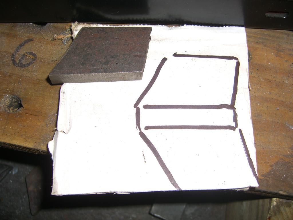 CIMG4677.jpg CIMG4676.jpg
Next I use a piece of 1 1/4" X 1/8" angle iron cut slightly oversized to bend and shape into the clip. I know I'm not the first to do this but I thought the photos and description might help others to make their own. CIMG4669.jpg
I have to give credit to Lars for selling me some of his clips so I could trial fit them, and try to come up with a design that would work for most guys with minimal grinding. The problem I had with Lars clip was the amount of grinding that had to be done to the divider to make them fit right. With the clip I made you still need to grind the divider down .125" or 1/8". If you are doing this with the heads on the engine, look in the port to make sure the exhaust valves are closed. Stuff some paper towels in the ports and be sure to blow any metal shavings out when you are done. Here's what the stock port looks like on a "C" casting.
CIMG4662.jpg
CIMG4663.jpg
It took me less than a minute to grind down my head with a four inch grinder.
CIMG4670.jpg
Here's the tools I used to make the clips, along with a welder, bench grinder and vice.
CIMG4668.jpg
I suggest you start by making a card board pattern that fits nicely in the port.
 CIMG4677.jpg CIMG4676.jpg
Next I use a piece of 1 1/4" X 1/8" angle iron cut slightly oversized to bend and shape into the clip. I know I'm not the first to do this but I thought the photos and description might help others to make their own. CIMG4669.jpg
October 26th, 2014, 11:02 PM
#836
Registered User
Thread Starter
Join Date: Apr 2010
Posts: 978
Here I'm using the vice to fold over the angle iron. If the metal is too thin it will crack.
CIMG4679.jpg
CIMG4682.jpg
After the clip is folded over I will weld a bead across the top to strengthen it, and allow me to square it off.

CIMG4686.jpg
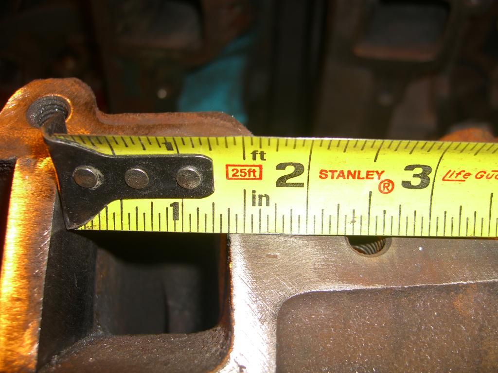
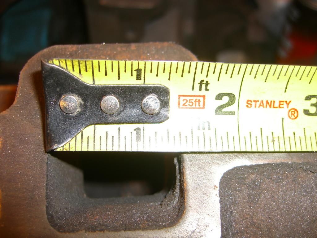
Next comes cutting the clip close to it's finish size using the card board for the template. A Sawzall works best. Next comes a lot of grinding and shaping to get the clip to fit nice. The deepest part of the clip should be sharpened near the head bolt hole. A lot of material will be ground off. The clip will be approximately 1/4" wide which is wider than the gasket, but that is OK. This will match the width of the outer exhaust ports.
CIMG4688.jpg
CIMG4689.jpg
I use a file when it gets close to give a nice square sealing surface.
CIMG4694.jpg
Lars clip is on the left, mine is on the right.
CIMG4699.jpg
CIMG4700.jpg
Most guys JB weld these clips in place. I don't know how well the JB weld will hold up to the heat in the exhaust runner. If it does break down, the clip will be held in place by the header. This modification should help to seal up your headers, give a slight performance increase, and no chance of cracking your head by welding it.
CIMG4679.jpg
CIMG4682.jpg
After the clip is folded over I will weld a bead across the top to strengthen it, and allow me to square it off.

CIMG4686.jpg
Next comes cutting the clip close to it's finish size using the card board for the template. A Sawzall works best. Next comes a lot of grinding and shaping to get the clip to fit nice. The deepest part of the clip should be sharpened near the head bolt hole. A lot of material will be ground off. The clip will be approximately 1/4" wide which is wider than the gasket, but that is OK. This will match the width of the outer exhaust ports.
CIMG4688.jpg
CIMG4689.jpg
I use a file when it gets close to give a nice square sealing surface.
CIMG4694.jpg


Lars clip is on the left, mine is on the right.
CIMG4699.jpg
CIMG4700.jpg
Most guys JB weld these clips in place. I don't know how well the JB weld will hold up to the heat in the exhaust runner. If it does break down, the clip will be held in place by the header. This modification should help to seal up your headers, give a slight performance increase, and no chance of cracking your head by welding it.
November 6th, 2014, 04:15 AM
#837
Registered User
Thread Starter
Join Date: Apr 2010
Posts: 978
Cross Section
Today I finally took some time to abuse the industrial band saw we have at my shop. This thing is as old as dirt. Spins real slow, and I'm sure the blade is pretty dull. Anyway, this cracked head turned out pretty good. This chunk will make a hell of a paper weight. I've been studying it for a while tonight. I should have done this a long time ago. It's one thing to look at photos of the cross sectioned head, but it's no where near as useful as having one in your hands, to be able to measure and map out. Most photos I've seen of the cross section were stock heads. My photos are of a ported BB "Ga" casting. This port work is identical to what's on Don's SB engine and my BB engine. I've started working on my other cracked head that will be my test head for the max effort port job. I will post up some photos of that head very soon. Hope you guys enjoy these photos. If anyone wants any specific measurements, just let me know. I painted the water jackets blue-
CIMG4711.jpg
CIMG4712.jpg
CIMG4715.jpg
CIMG4713.jpg
CIMG4711.jpg
CIMG4712.jpg
CIMG4715.jpg
CIMG4713.jpg
November 17th, 2014, 08:04 PM
#839
Registered User
Thread Starter
Join Date: Apr 2010
Posts: 978
x-perimental Head Porting
Well guys I'm back to grinding. The tracks closed, and the snow is coming down. It has been brought to my attention that most of what I've shown you is just the basics. I have learned my skills from Joe Mondello, reading articles, and by simply doing. I really don't have the scientific knowledge to pass on why you do certain things on our heads. I will try to do some more research and pass on that information to you. Obviously in our heads there are high flow areas and low flow areas (dead spots). I will talk to the experts and pass on as much information as I can. I have decided to move foreword with the cracked head Jeremy gave me for research purposes. I started raising the roof on one port a while back. I went .500" above stock location. I went through into a water jacket about 3/4" in front of the guide. I welded that hole up and also welded the floor to raise it 1/4". I also went through under the threaded rocker stud hole. I will cover that with JB Weld before flow testing. I also carved into one of the push rod holes. I will sleeve that with thin wall tubing.
Here's a photo of a stock "C" casting intake port. It measures 2.340"-
CIMG4729.jpg
When I got this head it had some porting done. The bumps were gone and the roof was raised .040" to match the gasket. This port was just cleaned up a little by me, but left with minimal work. I will do the bowl some-
CIMG4730.jpg
CIMG4736.jpg
This next runner I raised the roof .160" and widened the sides a bit, not too crazy. I just straightened out the curves in the sides. I did a lot of bowl work on this one, pulling it back to open the long side radius, and I took a lot off the short side radius. This has been set up for 2.070" valve-
CIMG4734.jpg
CIMG4743.jpg
CIMG4742.jpg
When I got this head it was set up for 1.99" intake valves. I will do the 2.070" on all but one port. My max effort will get 2.120" valve. Here it is. Looks a little rough, but I'm not done yet-
CIMG4731.jpg
I welded up and raised the floor .250" that really straightened out the entry. If I were to utilize this type of a port, I would have to customize an intake. Might even have a sheet metal intake made. I may try to raise the intake mounting holes to the same height, drill and tap- see if I hit water. I'm thinking a Victor with an adapter plate might work well. Here's some more shots of the raised port-
CIMG4740-1.jpg
CIMG4733.jpg
CIMG4732.jpg
I don't really want to tell you guys how many hours I have into this port. Kind of makes me sick to my stomach that it will never be used on an engine again. This head is strictly for research purposes. I have one more intake port to do on this head. I have started by welding up the floor - it's still rough, and I was going to raise the roof .250" on that one-
CIMG4738.jpg
I haven't really touched any of the exhaust ports. Do you guys have any thoughts, suggestions or requests of what you would like to see flow numbers on? One thing we need to keep in mind is that flow numbers don't always translate into good dyno numbers or track results. It is the only reference number that we have to gage the porters performance gains before running.
Hey Don this one's for you-
CIMG4748-1.jpg


