Home Porting Techniques
 April 29th, 2014, 04:45 PM
#641
Registered User

Join Date: Apr 2014
Posts: 22
redneck482, thanks for sharing the photos of your port work. It's real hard for me to tell from the photos if any further work would be a benefit. From the angle of the shot, I think you might have been able to remove a little bit more in the bowl area, on the intake left side. I can't see the exhaust bowl too well. In any case, nice work. Would you care to share any lower lift flow numbers? How do you plan to rough up the port, with a media blast? Are you worried about damaging the seat area, or do you have finish valve job work to do?
I usually use a 40grit roll and go slow.. I haven't found any dif in power
from that type of finish to a super rough one.. more I feel the super rough the fuel tumbles out of suspension. On my billet heads I use a 60grit roll and turn it real slow and that seems to work real nice.
The heads def could have more work done to them absolutely.. opening the pinch area at the pushrod.. by the head bolt.. they were more intended as a med port job .. but I recently started poking at them again and changed the valve angles at the seat and the width..
I was lookin all over for that darn sheet .. I'd be happy to tell you what they flowed .. I will have to stick it back on the flow bench and reflow it. I found the sheet for my quick bowl blended H heads.. Ill reflow them after the lil bit more work. Def you guys can do at home with some patience.. that is what the forums are for.. helping guys out

 April 30th, 2014, 05:20 PM
#644
Engine Builder
Join Date: Jan 2010
Location: Louisville, ohio
Posts: 552
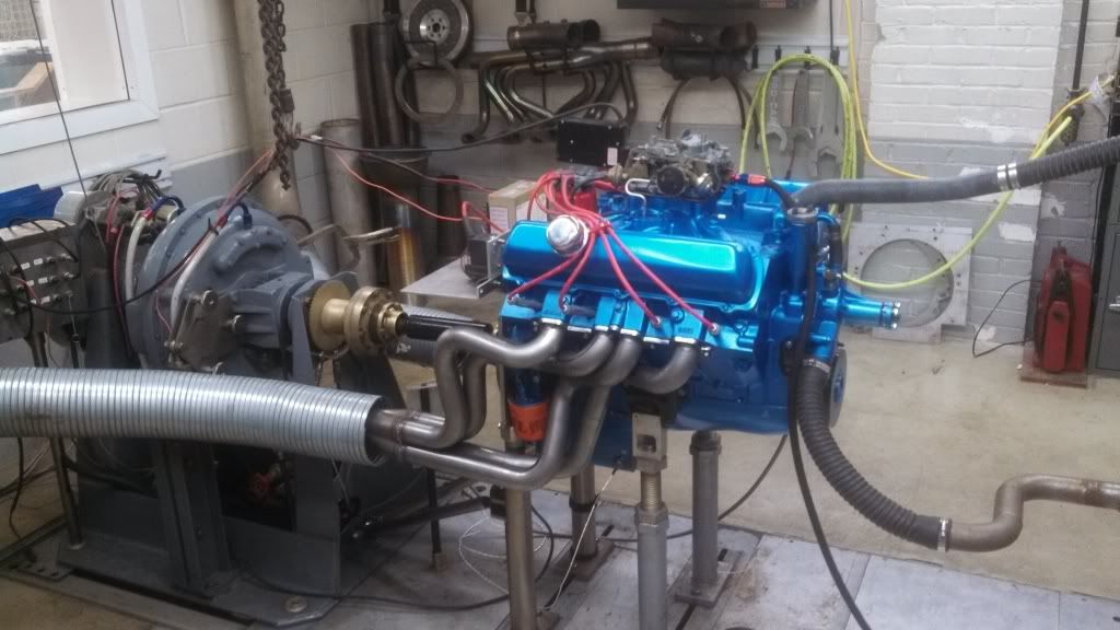
Redneck, here is a shot of the dyno facility I use. True state of the art equipment. Can run up to 2900HP and also over 10,000rpm with out a reducer. They can do everything but combustion analysis which is another $60K worth of equipment. The dyno can be run on simulation mode which can be set up to simulate a drag strip pass, road race, NASCAR race etc. Once a motor is fired and verified that no leaks are present and the engine is sound they put it on a break in program that loads and unloads the engine to roughly 60% of max load to seat the rings and also breaks in the cam if it's a flat tappet.
IMG_20131026_094841_775_zps7c180d8a.jpg
Also have a chassis dyno that will handle 2500HP.
IMG_20131026_094841_775_zps7c180d8a.jpg
Also have a chassis dyno that will handle 2500HP.
Last edited by Smitty275; April 30th, 2014 at 05:24 PM.
April 30th, 2014, 10:41 PM
#646
Registered User
Join Date: Apr 2014
Posts: 22
Redneck, here is a shot of the dyno facility I use. True state of the art equipment. Can run up to 2900HP and also over 10,000rpm with out a reducer. They can do everything but combustion analysis which is another $60K worth of equipment. The dyno can be run on simulation mode which can be set up to simulate a drag strip pass, road race, NASCAR race etc. Once a motor is fired and verified that no leaks are present and the engine is sound they put it on a break in program that loads and unloads the engine to roughly 60% of max load to seat the rings and also breaks in the cam if it's a flat tappet.
Also have a chassis dyno that will handle 2500HP.

Also have a chassis dyno that will handle 2500HP.
Very nice

Im sure the guys here enjoy the eye candy.. that's why I asked.
I noticed your web page was down.
April 30th, 2014, 10:42 PM
#647
Registered User
Join Date: Apr 2014
Posts: 22
That's Kewl Smitty.. I was just curious what kind you used at the shop. I built mine with Audie Tech stuff.. super fast to use and very accurate.. I'm quite happy with how it's worked over the years.
I figured you had some pretty nice stuff there kicking around.
 April 30th, 2014, 10:47 PM
#649
Registered User
Join Date: Apr 2014
Posts: 22
I apologise for the split in the post.. my lap top is laggin and acting weird..
mines a 901 dyno that was modded and pimped out with the upgraded dog bone.. just replacing the card slots as we speak.. they finally gave their last squeeze on this lil 347 yesterday.. thankfully it finished up before it decided to die.. Expensive beast to keep operational to say the least..
Mind you my buddies 902 he just bought.. hes cursing left and right.. its like they made the seals in China now.. anything around 1300hp and it pushes the seal out of the back of the absorber.... first month he had it and a board crashed..2500$ to fix that..
 April 30th, 2014, 11:16 PM
#651
Registered User
Thread Starter
Join Date: Apr 2010
Posts: 978
Bummer day
I went to the machine shop today to pick up some C's I had dropped off for cleaning and one of my GA heads that I found some problems with. Things did not go well. They did a nice job of cleaning up the C's, but they were supposed to run a bowl hog in to open them up to save me porting time. There was some miscommunication as far as my expectations. They had me bring in one of each of the valves to be used. These heads are going to be 2.125" intake and 1.680" exhaust. They cut the intake seats some, but not nearly enough to go out to 2.125". They didn't touch the exhaust. I knew the price sounded to good to be true. Needless to say the extra time they spent to cut the seats out was useless to me. Here's some photos-
CIMG4601.jpg
CIMG4600.jpg
I'm glad they didn't do anything to the exhaust bowl. Then it would have been $120 flushed down the toilet.
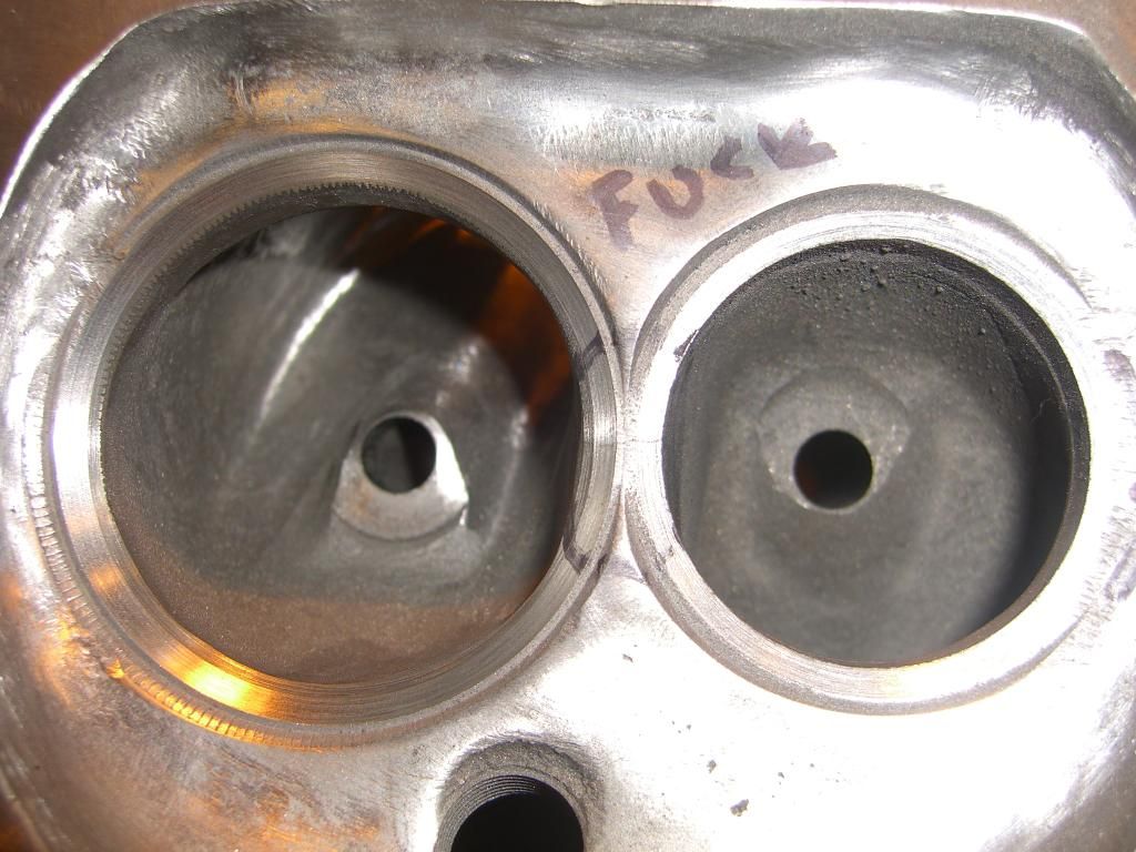
On to some more depressing news. A couple weeks ago I started to grind the seats on my GA heads. The young man who started porting on these heads before me had ground into three exhaust seats so far that they were going to have to be replaced. I also found a crack going across the intake and exhaust on one chamber. I never saw this until I started to grind into the seats. These heads were supposedly checked for cracks at a different machine shop many years ago. I don't know if they were magnafluxed, or pressure tested. In any case they were supposed to grind out the seats to see if the crack is in the head below them as well. They pretty much said why bother and never did cut the seats out. I'm going to try Smitty's method with the welder, to try to remove them. Here's some ugliness-
CIMG4599.jpg
CIMG4598.jpg
So on a brighter note Jeremy stopped by last Sunday. We put together his heads, drank a few beers and had a very good time. He even brought me a G casting head to match my non cracked GA. So now I get to start over on that one. On another sad note, we went to load up his cast iron intake that we were both so proud of, and he spotted a big crack across one of the runners. Man talk about a waste of time. I drilled and tapped and ground on that thing for hours. Coppercutlass had some time invested in cleaning it up. It looked great until we flipped it over. What a bummer. I guess that's why it was free. At least we have a Holley Street Dominator coming soon from my good friend Dr. Dan in Florida. J(Chicago) is going to have his heads flowed, but money is real tight for me right now. I have to wait before I have any BB heads flowed. I did do a little more porting on the junk E head I have here. I was doing a little experimenting on removing the guide and I finally hit water. I really didn't want to, but I kind of expected it. I was just trying to see how far we could go. I know removing the lower part of the guide is not recommended because of valve stability, but I just wanted to see what kind of flow numbers could be achieved by doing this-
CIMG4606.jpg
CIMG4607.jpg
CIMG4604.jpg
CIMG4601.jpg
CIMG4600.jpg
I'm glad they didn't do anything to the exhaust bowl. Then it would have been $120 flushed down the toilet.
On to some more depressing news. A couple weeks ago I started to grind the seats on my GA heads. The young man who started porting on these heads before me had ground into three exhaust seats so far that they were going to have to be replaced. I also found a crack going across the intake and exhaust on one chamber. I never saw this until I started to grind into the seats. These heads were supposedly checked for cracks at a different machine shop many years ago. I don't know if they were magnafluxed, or pressure tested. In any case they were supposed to grind out the seats to see if the crack is in the head below them as well. They pretty much said why bother and never did cut the seats out. I'm going to try Smitty's method with the welder, to try to remove them. Here's some ugliness-

CIMG4599.jpg
CIMG4598.jpg
So on a brighter note Jeremy stopped by last Sunday. We put together his heads, drank a few beers and had a very good time. He even brought me a G casting head to match my non cracked GA. So now I get to start over on that one. On another sad note, we went to load up his cast iron intake that we were both so proud of, and he spotted a big crack across one of the runners. Man talk about a waste of time. I drilled and tapped and ground on that thing for hours. Coppercutlass had some time invested in cleaning it up. It looked great until we flipped it over. What a bummer. I guess that's why it was free. At least we have a Holley Street Dominator coming soon from my good friend Dr. Dan in Florida. J(Chicago) is going to have his heads flowed, but money is real tight for me right now. I have to wait before I have any BB heads flowed. I did do a little more porting on the junk E head I have here. I was doing a little experimenting on removing the guide and I finally hit water. I really didn't want to, but I kind of expected it. I was just trying to see how far we could go. I know removing the lower part of the guide is not recommended because of valve stability, but I just wanted to see what kind of flow numbers could be achieved by doing this-
CIMG4606.jpg
CIMG4607.jpg
CIMG4604.jpg
May 1st, 2014, 03:11 PM
#652
Engine Builder
Join Date: Jan 2010
Location: Louisville, ohio
Posts: 552
Freak, you need to add an "ed" to your chamber graffiti because that's what that head is. First off those look to be induction hardened seats, not hardened inserts, so they are not coming out unless machined for a new seat. Secondly that crack goes clear through both intake and exhaust seat and down into the port divider. It is not fixable by any means. There are a few who will tell you they can repair it, but I 100% guarantee it will crack right back across the seats.
Redneck, I have a Superflow SF600 for a flow bench.
Redneck, I have a Superflow SF600 for a flow bench.
May 1st, 2014, 03:19 PM
#653
Engine Builder
Join Date: Jan 2010
Location: Louisville, ohio
Posts: 552
I think Rocket Racing has crank scrapers. Personally not overly fond of them. The crank scrapers I mean. Just can't see scraping the oil off when it has no where to go. This is just my thinking on the subject. If the oil is scraped off and it falls back to the pan wouldn't the windage just keep pushing the oil back up the side of the pan and eventually be "thick" enough that the crank would be cutting through what has been scrapped off?
May 2nd, 2014, 11:26 AM
#655
Engine Builder
Join Date: Jan 2010
Location: Louisville, ohio
Posts: 552
That's even the pic I was looking for. I'll find it some day. Anyhow that's my branch. The fixture that you see on there is an Olds head specific fixture. It has holes in it to locate the head using the dowel pins just like on the block.
May 4th, 2014, 05:37 AM
#656
Registered User
Thread Starter
Join Date: Apr 2010
Posts: 978
Interesting
I can't believe this thread has had over 25,000 views. I didn't realize home porting was so popular. I want to thank everyone that has given input, and inspired others to pick up a dye grinder, or at least throw away their Dremel tool. As a token of my appreciation, I would like to offer up a cross section piece of a BB Oldsmobile head. I have two heads that I am going to section with the industrial band saw at work. These are pretty cool to study for water jacket layout. They are definitely a conversation piece. PM me if anyone has interest in one.
May 4th, 2014, 07:12 AM
#657
Registered User
Join Date: Dec 2013
Posts: 354
I can't believe this thread has had over 25,000 views. I didn't realize home porting was so popular. I want to thank everyone that has given input, and inspired others to pick up a dye grinder, or at least throw away their Dremel tool. As a token of my appreciation, I would like to offer up a cross section piece of a BB Oldsmobile head. I have two heads that I am going to section with the industrial band saw at work. These are pretty cool to study for water jacket layout. They are definitely a conversation piece. PM me if anyone has interest in one.
May 5th, 2014, 09:17 AM
#658
Connoisseur d'Junque
Join Date: Sep 2010
Location: The Hudson Valley
Posts: 21,183
Okay, when this thread first popped up, I thought, "That looks like it could be useful some day" and subscribed, but I've been busy and there was a lot going on, so I didn't follow it every day.
Springtime rolled around and it was time to do some work on the car.
I knew I had a bad exhaust valve, so clearly at least one head had to come off.
Since I had bought two rebuilt heads cheap at a flea market a few years ago "just in case," I thought this would be a good use for them.
I'd looked them over casually (no damage, very little running time, even, normal combustion patterns), but had not ever gotten out the micrometer.
Well... On closer inspection, it looks like they had a four year old running the machines that day. I think they're usable for my stock engine that will never get near 5,000 RPM, but I need to do some messin' with them, and decided it was time to take a glance at this old thread.
I downloaded the pages and turned it into a single pdf document so that i could read it whenever I had the chance.
It's over 390 pages.
Now that I've read them all (and taken notes), and now that I've checked out what I've got, I need to ask a few questions.
I am asking them here, and not in a separate thread, because I believe that the answers will contribute to the Home Porting discussion, and may help others as well.
Thanks to '67 Cutlass Freak for starting this thread, and to Smitty, J, Brad, and eveyone else who has contributed!
Questions:
Amusingly, the "porting" that I've begun to do on one of these heads is to enlarge the CCs of a head that's been milled something like 0.050"-0.060" and has a volume of 56cc. I've learned a lot just starting the job last week, and a lot more from reading this thread.
I expect I'll do some "real" porting another time.
Oh, and here's my homemade stem height gauge:


- Eric
Springtime rolled around and it was time to do some work on the car.
I knew I had a bad exhaust valve, so clearly at least one head had to come off.
Since I had bought two rebuilt heads cheap at a flea market a few years ago "just in case," I thought this would be a good use for them.
I'd looked them over casually (no damage, very little running time, even, normal combustion patterns), but had not ever gotten out the micrometer.
Well... On closer inspection, it looks like they had a four year old running the machines that day. I think they're usable for my stock engine that will never get near 5,000 RPM, but I need to do some messin' with them, and decided it was time to take a glance at this old thread.
I downloaded the pages and turned it into a single pdf document so that i could read it whenever I had the chance.
It's over 390 pages.
Now that I've read them all (and taken notes), and now that I've checked out what I've got, I need to ask a few questions.
I am asking them here, and not in a separate thread, because I believe that the answers will contribute to the Home Porting discussion, and may help others as well.
Thanks to '67 Cutlass Freak for starting this thread, and to Smitty, J, Brad, and eveyone else who has contributed!
Questions:
- What is the spec. for spring installed heights for stock #7 heads?
I've measured my old, unmolested head, but the factory doesn't give one, and my "new" ones are all over the place. - What sort of a coil bind clearance would you recommend for a basically stock (very mild cam), 4,500 RPM-on-rare-occasions 350?
- What is the actual spec. for valve stem height above the valve cover sealing surface (as measured by the factory tool)?
The CSM says just use the tool.
I have seen 1.220+/-5 listed as the from-the-spring-seat distance for big blocks, which, using the CSM's math, translates to 1.190+/-5 for the small blocks, but the #7s have the spring pockets cut differently for intake and exhaust, and it doesn't feel right.
I've made an adjustable factory tool for myself and measured all of my stem heights, but now I need to know what to do with the information.
Amusingly, the "porting" that I've begun to do on one of these heads is to enlarge the CCs of a head that's been milled something like 0.050"-0.060" and has a volume of 56cc. I've learned a lot just starting the job last week, and a lot more from reading this thread.
I expect I'll do some "real" porting another time.
Oh, and here's my homemade stem height gauge:
- Eric
May 5th, 2014, 07:14 PM
#659
Registered User
Thread Starter
Join Date: Apr 2010
Posts: 978
[QUOTE=MDchanic;693205]
Questions:
1. I pulled this spec from this FAQ link that was previously posted-
http://oldsjunction.classicoldsmobil...sfaq/ofhed.htm
Valve Spring Pockets
"Many heads use rotators on the intake and exhaust valves. So yes they do have deeper spring seats than the earlier models with solid retainers. The deeper spring seat is required to compensate for the thicker rotator style retainer. The spring installed height for all (stock) big block heads is 1.670" regardless of the retainer style.
If Comp Cams calls for a taller installed height, you can use different (solid) retainers to make up the difference, rather than machining the spring seats. These should be available thru Comp Cams, if not they are from other brands. I would recommend using steel retainers over aluminum on a street application. As the spring dampers will tend to dig into the aluminum, thereby sending aluminum particles through the engine. When using aftermarket retainers, be sure to check for clearance between the rocker arm and retainer. This can be done on the bench. As with any cam, to optimize its potential, always use the manufactures recommended matching springs.
With .540" lift, be sure to check for adequate clearance between the retainer and valve guide (with whatever seals you are using installed). The guide may very well need to be shortened. If you are planning on using stock style rocker arms, make sure the slot is long enough for the amount of lift. The slot may need to be elongated with some of the "replacement" style arms on the market.
Be careful with aftermarket valve springs. Many heads use shallow spring seats. Many aftermarket springs are designed for the more common deeper seats, and won't install to the correct height with the springs you get with the kit. In fact it takes a lot of muscle to get them installed at all. The height will end up .090" too short. My machine shop almost sent me home with my heads set up like this until I checked the dimension myself. Even then they tried to tell me it wouldn't be a problem. The best solution is to machine the spring seats .090" deeper to get the correct installed height and also the correct preload on the springs. I'm sure you would bend valves, pushrods etc. if you don't get them right. Another solution I guess would be to use longer than stock valves (Mondello sells them), but I'm not sure what other problems they would cause. With a 403, the spring seats should be at the depth that matches the Edelbrock package. I know they are for 350 heads, #6 and above."
2. With a mild cam, and stock ratio rockers - 1.6, you will not have to worry about coil bind whatsoever. It only comes into play with higher lift cams. When choosing your cam, in a performance application, you need to match the springs to that cam. Here's the link Jim posted about coil bind-
http://www.lunatipower.com/Tech/Valv...pringTech.aspx
If you are planning on running adjustable roller rockers, you will not have to worry about valve stem height. If you are planning on running the stock rockers then you should set the valve height to spec. You may be forced to run a custom length push rod since your heads have been milled that far. If that is the case, you will need to pick up an adjustable pushrod, for use during mock up, to measure what length you will need to order.
3. I went out to measure my gage for you. The problem is the valve is not at a 90 degree angle to the valve cover surface. I put a steel ruler under the bridge to lift it up, and measured the distance best I could with a snap gage. It came out to 1.215"
The second photo looks off but I was not holding the micrometer in the right place for the photo-
CIMG4608.jpg
CIMG4609.jpg
After you set the height on your tool, lock it down. You could even weld it in place, or use a Nylock nut. Now get to work, and please post up some photos.
Questions:
- What is the spec. for spring installed heights for stock #7 heads?
I've measured my old, unmolested head, but the factory doesn't give one, and my "new" ones are all over the place. - What sort of a coil bind clearance would you recommend for a basically stock (very mild cam), 4,500 RPM-on-rare-occasions 350?
- What is the actual spec. for valve stem height above the valve cover sealing surface (as measured by the factory tool)?
The CSM says just use the tool.
I have seen 1.220+/-5 listed as the from-the-spring-seat distance for big blocks, which, using the CSM's math, translates to 1.190+/-5 for the small blocks, but the #7s have the spring pockets cut differently for intake and exhaust, and it doesn't feel right.
I've made an adjustable factory tool for myself and measured all of my stem heights, but now I need to know what to do with the information.
1. I pulled this spec from this FAQ link that was previously posted-
http://oldsjunction.classicoldsmobil...sfaq/ofhed.htm
Valve Spring Pockets
"Many heads use rotators on the intake and exhaust valves. So yes they do have deeper spring seats than the earlier models with solid retainers. The deeper spring seat is required to compensate for the thicker rotator style retainer. The spring installed height for all (stock) big block heads is 1.670" regardless of the retainer style.
If Comp Cams calls for a taller installed height, you can use different (solid) retainers to make up the difference, rather than machining the spring seats. These should be available thru Comp Cams, if not they are from other brands. I would recommend using steel retainers over aluminum on a street application. As the spring dampers will tend to dig into the aluminum, thereby sending aluminum particles through the engine. When using aftermarket retainers, be sure to check for clearance between the rocker arm and retainer. This can be done on the bench. As with any cam, to optimize its potential, always use the manufactures recommended matching springs.
With .540" lift, be sure to check for adequate clearance between the retainer and valve guide (with whatever seals you are using installed). The guide may very well need to be shortened. If you are planning on using stock style rocker arms, make sure the slot is long enough for the amount of lift. The slot may need to be elongated with some of the "replacement" style arms on the market.
Be careful with aftermarket valve springs. Many heads use shallow spring seats. Many aftermarket springs are designed for the more common deeper seats, and won't install to the correct height with the springs you get with the kit. In fact it takes a lot of muscle to get them installed at all. The height will end up .090" too short. My machine shop almost sent me home with my heads set up like this until I checked the dimension myself. Even then they tried to tell me it wouldn't be a problem. The best solution is to machine the spring seats .090" deeper to get the correct installed height and also the correct preload on the springs. I'm sure you would bend valves, pushrods etc. if you don't get them right. Another solution I guess would be to use longer than stock valves (Mondello sells them), but I'm not sure what other problems they would cause. With a 403, the spring seats should be at the depth that matches the Edelbrock package. I know they are for 350 heads, #6 and above."
2. With a mild cam, and stock ratio rockers - 1.6, you will not have to worry about coil bind whatsoever. It only comes into play with higher lift cams. When choosing your cam, in a performance application, you need to match the springs to that cam. Here's the link Jim posted about coil bind-
http://www.lunatipower.com/Tech/Valv...pringTech.aspx
If you are planning on running adjustable roller rockers, you will not have to worry about valve stem height. If you are planning on running the stock rockers then you should set the valve height to spec. You may be forced to run a custom length push rod since your heads have been milled that far. If that is the case, you will need to pick up an adjustable pushrod, for use during mock up, to measure what length you will need to order.
3. I went out to measure my gage for you. The problem is the valve is not at a 90 degree angle to the valve cover surface. I put a steel ruler under the bridge to lift it up, and measured the distance best I could with a snap gage. It came out to 1.215"
The second photo looks off but I was not holding the micrometer in the right place for the photo-
CIMG4608.jpg
CIMG4609.jpg
After you set the height on your tool, lock it down. You could even weld it in place, or use a Nylock nut. Now get to work, and please post up some photos.
May 6th, 2014, 09:16 AM
#660
Connoisseur d'Junque
Join Date: Sep 2010
Location: The Hudson Valley
Posts: 21,183
Okay, thanks. That there's some good information.
So, the measured height of Tool BT-6428 is 1.215", which, subtracting 0.035 as per the CSM, leaves a maximum smallblock stem height of 1.180".
Interestingly, the CSM does not give a minimum height, presumably because valve seats recede or are ground, but do not suddenly grow new material. Of course, this does not take into consideration the possibility of some dodo installing new hardened valve seats at a wide variety of depths...
Have you ever heard of a specific minimum acceptable valve stem height? That is to say, a height at which you would get a ticking valve, or would need a longer pushrod?
On the other side of things, I believe there should be no problem in a stock-level application with shimming the rocker pivots upward to allow for valves that were a bit too long, correct? Along those lines, I did the math to confirm, and the amount to raise the pivots must be 1.6x the excess valve stem height to get the lifter back where it should be, right?
These points lead to the question: What is the definitive operating range of the hydraulic lifters?
That is: How much variation in valve train length can they tolerate, and in which directions?
The CSM seems to be most concerned with valves that sit too high, which could cause a valve not to close, or jam the lobe, lifter, and pushrod, and which should not be difficult to correct through shims, but makes no mention of a lower operating threshold, which would cause ticking, or, worse, reduced performance but no ticking, if almost too low, but not low enough to be loose.
Finally, you give a spring installed height for big blocks of 1.670". Any idea whether smallblocks are the same?
The springs in the original head (#5, no rotators) are at an average of 1.680", +/-0.015", for whatever that's worth.
Now here's the thing: the spring heights in the #7 heads average 1.553" for the exhaust valves (minus an outlier") ) and 1.790" for the intake valves.
) and 1.790" for the intake valves.
If I subtracted 0.100" from the intakes and gave it to the exhausts, say, by swapping the rotators to the other type valves, they'd all average 1.670", just like the big blocks, and just like the other #5 head I took off.
This fact, coupled with how easy it is to compress the springs on the intakes and how hard it is to compress the exhausts, makes me wonder whether perhaps Bozo put the rotators on the wrong valves.
I checked the '71 CSM on this, and, believe it or not, it says both things. What's the real dinkum?
So, processing what I know so far, I think my plan is to relieve the other CCs to slightly increase CR (my old man mailed me a depth micrometer, so I was able to measure the deck height properly, and that, plus the fact that the Fel-Pro gaskets are 4.25" in diameter and not 4.126", leaves me only needing to remove about 2cc from each chamber), calculate my shim thicknesses for the seven or so valves that are high, install the heads and see if the valves that are low actually seem loose or tick, or if they seem okay. Another option, which may or may not be a BAD IDEA, would be to grind the bottoms of a few rocker pivots - it may be hard to get them square, but if I got them close, the worst thing that would happen would be for the rockers to wear and start to tick, at which point I could replace the rockers and pivots. Right?
Thanks!
- Eric
So, the measured height of Tool BT-6428 is 1.215", which, subtracting 0.035 as per the CSM, leaves a maximum smallblock stem height of 1.180".
Interestingly, the CSM does not give a minimum height, presumably because valve seats recede or are ground, but do not suddenly grow new material. Of course, this does not take into consideration the possibility of some dodo installing new hardened valve seats at a wide variety of depths...
Have you ever heard of a specific minimum acceptable valve stem height? That is to say, a height at which you would get a ticking valve, or would need a longer pushrod?
On the other side of things, I believe there should be no problem in a stock-level application with shimming the rocker pivots upward to allow for valves that were a bit too long, correct? Along those lines, I did the math to confirm, and the amount to raise the pivots must be 1.6x the excess valve stem height to get the lifter back where it should be, right?
These points lead to the question: What is the definitive operating range of the hydraulic lifters?
That is: How much variation in valve train length can they tolerate, and in which directions?
The CSM seems to be most concerned with valves that sit too high, which could cause a valve not to close, or jam the lobe, lifter, and pushrod, and which should not be difficult to correct through shims, but makes no mention of a lower operating threshold, which would cause ticking, or, worse, reduced performance but no ticking, if almost too low, but not low enough to be loose.
Finally, you give a spring installed height for big blocks of 1.670". Any idea whether smallblocks are the same?
The springs in the original head (#5, no rotators) are at an average of 1.680", +/-0.015", for whatever that's worth.
Now here's the thing: the spring heights in the #7 heads average 1.553" for the exhaust valves (minus an outlier
) and 1.790" for the intake valves.If I subtracted 0.100" from the intakes and gave it to the exhausts, say, by swapping the rotators to the other type valves, they'd all average 1.670", just like the big blocks, and just like the other #5 head I took off.
This fact, coupled with how easy it is to compress the springs on the intakes and how hard it is to compress the exhausts, makes me wonder whether perhaps Bozo put the rotators on the wrong valves.
I checked the '71 CSM on this, and, believe it or not, it says both things. What's the real dinkum?
So, processing what I know so far, I think my plan is to relieve the other CCs to slightly increase CR (my old man mailed me a depth micrometer, so I was able to measure the deck height properly, and that, plus the fact that the Fel-Pro gaskets are 4.25" in diameter and not 4.126", leaves me only needing to remove about 2cc from each chamber), calculate my shim thicknesses for the seven or so valves that are high, install the heads and see if the valves that are low actually seem loose or tick, or if they seem okay. Another option, which may or may not be a BAD IDEA, would be to grind the bottoms of a few rocker pivots - it may be hard to get them square, but if I got them close, the worst thing that would happen would be for the rockers to wear and start to tick, at which point I could replace the rockers and pivots. Right?
Thanks!
- Eric
May 6th, 2014, 06:28 PM
#661
Registered User
Thread Starter
Join Date: Apr 2010
Posts: 978
Okay, thanks. That there's some good information.
So, the measured height of Tool BT-6428 is 1.215", which, subtracting 0.035 as per the CSM, leaves a maximum smallblock stem height of 1.180".
Eric that's exactly where the stem height was on some stock C's I have here. I have never heard of a minimum height spec. It gets difficult when you try to install oversized stock length valves because they end up way short.
Interestingly, the CSM does not give a minimum height, presumably because valve seats recede or are ground, but do not suddenly grow new material. Of course, this does not take into consideration the possibility of some dodo installing new hardened valve seats at a wide variety of depths...
Usually when new seats are installed, they set the machine up to cut the depths the same. They also set up the seat grinder the same way to cut consistantly. It's only a problem if you have old school grinding equipment like me.
Have you ever heard of a specific minimum acceptable valve stem height? That is to say, a height at which you would get a ticking valve, or would need a longer pushrod?
I have never heard of minimum acceptable valve stem height specification. Back on page 8 I discussed the ideal range for the pushrod location in the lifter cup to be .030" to .050" I don't know how flexible the spec is. The other thing to keep in mind is the head gasket replacement will most likely be .040" where as originaly the thickness was .020" I believe. Don't forget your heads were milled. This math can get a little complicated.
On the other side of things, I believe there should be no problem in a stock-level application with shimming the rocker pivots upward to allow for valves that were a bit too long, correct? Along those lines, I did the math to confirm, and the amount to raise the pivots must be 1.6x the excess valve stem height to get the lifter back where it should be, right?
Sorry but this is wrong. The amount the valve travels downward is 1.6 times the distance the pushrod travels upward. I tried to measure a stock rocker, the distance from the center of the pivot point to the middle of the valve contact point is 1.45" the distance from the center pivot point to the center of the push rod cup is .91"
So if you take .91 x 1.6 = 1.456 now you see how the ratio works.
Now ad 1.45 + .91 = 2.36 This is the full rocker length from center of the valve contact area to center of the push rod cup.
So .91 / 2.36 = .386 let's just round that up to 40%.
Let's try to apply what we've learned. Say your valve stem height is .020" too low - .020/1.6=.0125 that's how far the push rod would have to travel to make up the distance. Now .020x.40 (that's our 40%)=.008
So you would need a .008" shim under the rocker to get your .020" difference. I told you it gets pretty complicated. Get the fish hooks out of your pockets and go buy adjustable rocker arms.
These points lead to the question: What is the definitive operating range of the hydraulic lifters?
That is: How much variation in valve train length can they tolerate, and in which directions?
Sorry I can't answer this.
The CSM seems to be most concerned with valves that sit too high, which could cause a valve not to close, or jam the lobe, lifter, and pushrod, and which should not be difficult to correct through shims, but makes no mention of a lower operating threshold, which would cause ticking, or, worse, reduced performance but no ticking, if almost too low, but not low enough to be loose.
Not to mention a pushrod coming out of the lifter.
Finally, you give a spring installed height for big blocks of 1.670". Any idea whether smallblocks are the same?
I have been told they are the same.
The springs in the original head (#5, no rotators) are at an average of 1.680", +/-0.015", for whatever that's worth.
Less is OK, anything over 1.670" should get a spring shim.
Now here's the thing: the spring heights in the #7 heads average 1.553" for the exhaust valves (minus an outlier) and 1.790" for the intake valves.
If I subtracted 0.100" from the intakes and gave it to the exhausts, say, by swapping the rotators to the other type valves, they'd all average 1.670", just like the big blocks, and just like the other #5 head I took off.
This fact, coupled with how easy it is to compress the springs on the intakes and how hard it is to compress the exhausts, makes me wonder whether perhaps Bozo put the rotators on the wrong valves.
I checked the '71 CSM on this, and, believe it or not, it says both things. What's the real dinkum?
I think you may be onto something. Hopefully someone else can chime in. It's been a while since I've messed around with anything that had rotators.
So, processing what I know so far, I think my plan is to relieve the other CCs to slightly increase CR (my old man mailed me a depth micrometer, so I was able to measure the deck height properly, and that, plus the fact that the Fel-Pro gaskets are 4.25" in diameter and not 4.126", leaves me only needing to remove about 2cc from each chamber), calculate my shim thicknesses for the seven or so valves that are high, install the heads and see if the valves that are low actually seem loose or tick, or if they seem okay. Another option, which may or may not be a BAD IDEA, would be to grind the bottoms of a few rocker pivots - it may be hard to get them square, but if I got them close, the worst thing that would happen would be for the rockers to wear and start to tick, at which point I could replace the rockers and pivots. Right?
Thanks!
I would not recomend going through final assembly until you mock it up and check the push rod length you will need. Your heads being milled that far will throw off the geometry of everything. Of course the thicker head gasket will help put you closer, but I think you're still going to be about .030" lower with the head than stock. That means your stock push rod is going to be .030" higher up. Now let's multiply .030"x1.6=.048"
That means the valve end of each of your rockers is now going to be .048" lower. How low are your valves? Is your head spinning from all this math? I need a beer now. You can make a fixture on the front of your bench grinder to grind the valve tips. Hope all this BS helps you.
- Eric
So, the measured height of Tool BT-6428 is 1.215", which, subtracting 0.035 as per the CSM, leaves a maximum smallblock stem height of 1.180".
Eric that's exactly where the stem height was on some stock C's I have here. I have never heard of a minimum height spec. It gets difficult when you try to install oversized stock length valves because they end up way short.
Interestingly, the CSM does not give a minimum height, presumably because valve seats recede or are ground, but do not suddenly grow new material. Of course, this does not take into consideration the possibility of some dodo installing new hardened valve seats at a wide variety of depths...
Usually when new seats are installed, they set the machine up to cut the depths the same. They also set up the seat grinder the same way to cut consistantly. It's only a problem if you have old school grinding equipment like me.
Have you ever heard of a specific minimum acceptable valve stem height? That is to say, a height at which you would get a ticking valve, or would need a longer pushrod?
I have never heard of minimum acceptable valve stem height specification. Back on page 8 I discussed the ideal range for the pushrod location in the lifter cup to be .030" to .050" I don't know how flexible the spec is. The other thing to keep in mind is the head gasket replacement will most likely be .040" where as originaly the thickness was .020" I believe. Don't forget your heads were milled. This math can get a little complicated.
On the other side of things, I believe there should be no problem in a stock-level application with shimming the rocker pivots upward to allow for valves that were a bit too long, correct? Along those lines, I did the math to confirm, and the amount to raise the pivots must be 1.6x the excess valve stem height to get the lifter back where it should be, right?
Sorry but this is wrong. The amount the valve travels downward is 1.6 times the distance the pushrod travels upward. I tried to measure a stock rocker, the distance from the center of the pivot point to the middle of the valve contact point is 1.45" the distance from the center pivot point to the center of the push rod cup is .91"
So if you take .91 x 1.6 = 1.456 now you see how the ratio works.
Now ad 1.45 + .91 = 2.36 This is the full rocker length from center of the valve contact area to center of the push rod cup.
So .91 / 2.36 = .386 let's just round that up to 40%.
Let's try to apply what we've learned. Say your valve stem height is .020" too low - .020/1.6=.0125 that's how far the push rod would have to travel to make up the distance. Now .020x.40 (that's our 40%)=.008
So you would need a .008" shim under the rocker to get your .020" difference. I told you it gets pretty complicated. Get the fish hooks out of your pockets and go buy adjustable rocker arms.
These points lead to the question: What is the definitive operating range of the hydraulic lifters?
That is: How much variation in valve train length can they tolerate, and in which directions?
Sorry I can't answer this.
The CSM seems to be most concerned with valves that sit too high, which could cause a valve not to close, or jam the lobe, lifter, and pushrod, and which should not be difficult to correct through shims, but makes no mention of a lower operating threshold, which would cause ticking, or, worse, reduced performance but no ticking, if almost too low, but not low enough to be loose.
Not to mention a pushrod coming out of the lifter.
Finally, you give a spring installed height for big blocks of 1.670". Any idea whether smallblocks are the same?
I have been told they are the same.
The springs in the original head (#5, no rotators) are at an average of 1.680", +/-0.015", for whatever that's worth.
Less is OK, anything over 1.670" should get a spring shim.
Now here's the thing: the spring heights in the #7 heads average 1.553" for the exhaust valves (minus an outlier
) and 1.790" for the intake valves.If I subtracted 0.100" from the intakes and gave it to the exhausts, say, by swapping the rotators to the other type valves, they'd all average 1.670", just like the big blocks, and just like the other #5 head I took off.
This fact, coupled with how easy it is to compress the springs on the intakes and how hard it is to compress the exhausts, makes me wonder whether perhaps Bozo put the rotators on the wrong valves.
I checked the '71 CSM on this, and, believe it or not, it says both things. What's the real dinkum?
I think you may be onto something. Hopefully someone else can chime in. It's been a while since I've messed around with anything that had rotators.
So, processing what I know so far, I think my plan is to relieve the other CCs to slightly increase CR (my old man mailed me a depth micrometer, so I was able to measure the deck height properly, and that, plus the fact that the Fel-Pro gaskets are 4.25" in diameter and not 4.126", leaves me only needing to remove about 2cc from each chamber), calculate my shim thicknesses for the seven or so valves that are high, install the heads and see if the valves that are low actually seem loose or tick, or if they seem okay. Another option, which may or may not be a BAD IDEA, would be to grind the bottoms of a few rocker pivots - it may be hard to get them square, but if I got them close, the worst thing that would happen would be for the rockers to wear and start to tick, at which point I could replace the rockers and pivots. Right?
Thanks!
I would not recomend going through final assembly until you mock it up and check the push rod length you will need. Your heads being milled that far will throw off the geometry of everything. Of course the thicker head gasket will help put you closer, but I think you're still going to be about .030" lower with the head than stock. That means your stock push rod is going to be .030" higher up. Now let's multiply .030"x1.6=.048"
That means the valve end of each of your rockers is now going to be .048" lower. How low are your valves? Is your head spinning from all this math? I need a beer now. You can make a fixture on the front of your bench grinder to grind the valve tips. Hope all this BS helps you.
- Eric
Last edited by 67 Cutlass Freak; May 6th, 2014 at 07:59 PM.
May 6th, 2014, 07:11 PM
#662
Registered User
Join Date: Dec 2013
Posts: 354
Speaking of head gaskets what thickness is ideal for a street build? I got a set of Sealed Power in my Gasket kit think they are around .040 thick. Deck height and G heads I believe have never been milled so stock heights. Pistons are KB 277 30 over +15cc on stock rods. Trying to figure out compression, KB site says 10:1 but I am guessing it will be closer to 9.5 from what I have read.
Also here's a pic of the BT-6428 valve stem tool. I picked this up when my original plan was to do a stock type rebuild with stock rockers. Then of course I started looking at this site and my engine build ended up costing about 5 times as much, but hey it'll be worth it! The tool well it's basically a wall hanger now!!
Also here's a pic of the BT-6428 valve stem tool. I picked this up when my original plan was to do a stock type rebuild with stock rockers. Then of course I started looking at this site and my engine build ended up costing about 5 times as much, but hey it'll be worth it! The tool well it's basically a wall hanger now!!
Last edited by bainer1290; May 6th, 2014 at 07:16 PM.
May 6th, 2014, 07:45 PM
#663
Registered User
Thread Starter
Join Date: Apr 2010
Posts: 978
bainer1290, call Smitty about the head gaskets. He offers a variety of thicknesses priced reasonably. I'm sure what you have would work fine, but if you're trying to build a high performance engine, don't give up that much compression, due to head gasket thickness. The Cometics are very expensive. There's other options.
May 6th, 2014, 07:53 PM
#664
Registered User
Join Date: Dec 2013
Posts: 354
bainer1290, call Smitty about the head gaskets. He offers a variety of thicknesses priced reasonably. I'm sure what you have would work fine, but if you're trying to build a high performance engine, don't give up that much compression, due to head gasket thickness. The Cometics are very expensive. There's other options.
May 6th, 2014, 08:16 PM
#665
Registered User
Thread Starter
Join Date: Apr 2010
Posts: 978
Breaking news about Resbond fill on ROP
I just saw this post over on ROP - it doesn't look good for the Resbond --->
http://realoldspower.prophpbb.com/topic815.html
Posted by T311 � Tue May 06, 2014 8:07 pm
At the same time you were doing this, I was putting the same product in my heads. After a season of racing, I can say that mine isn't holding up. It seems to be mechanically breaking down.
I pulled the intake and everything seemed intact, but I noticed on the head side of the intake gasket on one side was a build up of very fine ceramic powder - felt about like ash. I put new intake gaskets on and reinstalled the manifold. Went to the track and made 1 pass, and ended up needing to pull the intake again (unrelated issue).
Well, after just one additional pass, this time it burned right through the intake gasket. A small chunk of the Resbond fell out of the heat riser in the intake. Additionally, more of the very fine ceramic powder was being blasted into the heat riser. Well even that fine, ceramic is still abrasive and not something I want swirling around the exhaust ports, potentially ending up on exhaust seats.
It was nice to be able to work it cold, but it doesn't seem to be holding up. It didn't break up into chunks or anything, but seems to be eroding away, and I don't want an abrasive powder flying around my engine. I'm going to pull the heads and break it up and remove it.
Just thought I'd share my experience with it for those who read this thread.
Mike
May 6th, 2014, 08:21 PM
#666
Engine Builder
Join Date: Jan 2010
Location: Louisville, ohio
Posts: 552
Really busy here today. But will try to answer a few questions I picked up while skimming through here tonight.
Stock installed height is usually 1.700" give or take a few thousandths. With most aftermarket retainers you end up with 1.750 or 1.800 which opens up a world of spring options. When you change springs you need to be sure that the retainers fit the springs properly. Having them loose is asking for trouble in the long run. You should always have a minimum of .060 between open height and coil bind. This is not the distance between coils. This is the distance moved from open height to where the spring bottoms out, it binds together. You should also try to get a spring where you are running it as close as possible to its advertised open height. That is its engineered operating area. Up or down a little is OK but try not to veer far.
Head gaskets......yes Cometics are expensive. The huge positive is that you can clean them and reuse them over and over and over. If you wear the coating off give them a light coat of copper coat and use them again if you want. I was sitting at Cometic and sitting at the reps desk one day when a UPS box was brought in to him. It was from Warren Johnson and contained a pair if gaskets that had been on a Pro Stock dyno mule for 157 pulls with 7 (seven) different pairs of cylinder heads. They looked like new. You truly do get what you pay for with Cometic gaskets.
I prefer to run piston to head clearance at .040. I have ran at .035 successfully. But I wouldn't want to run it in a burnout box at 5k. Due to the Olds chamber design I've also ran as much as .100 piston to head with out issue when it was the only way to bring compression back to reasonable on a build done elseware and really botched. It still ended up at 11.2:1 and with the right can that long stroke 400 was one wicked piece. But I think it is best to stay right around .040" when its possible.
In a few weeks I'll be going to the dyno with a set of heads that have a complete different take on chamber design. These were done with input from an actual Olds engineer from back when the r&d was being done on these engines. Lots of interesting things were done and not all of them were put into practice even though they were actually better than what was put into production. Its been expensive but according the a combustion analysis program at a major piston manufacturer, which they used to design the piston, I think were going to be very pleased with one awesome pump gas build.
May 6th, 2014, 08:44 PM
#668
Connoisseur d'Junque
Join Date: Sep 2010
Location: The Hudson Valley
Posts: 21,183
Mike,
Yes, I do intend to install everything experimentally before making any "commitments" - I'm very cautious that way.
Shim springs over 1.670" (edit: or over 1.700", Smitty). Good, that's easy.
I have been considering the reduction in height caused by the milled head, and adding that in to my calculations.
As far as calculating the amount that the pushrod end of the rocker will relocate downward with a thinner head gasket or milling the head, I'm not convinced of your calculation (though I am not terribly convinced of my own either). Upon careful review, it seems to me that moving the pivot downward, but keeping the valve in the same place (in what is for now a theoretical system), should deflect the pushrod end downward half of the distance that the ratio would suggest, or 20% (assuming the near 60/40 ratio of 1.6:1).
Now, since the valve, in fact, moves downward with the head, that movement would deflect the pushrod end upward at 40% of the amount of head movement.
Adding these two numbers, I come up with a net movement of the pushrod end of 20% upward.
Now, there was a time when I was good at things like this, but it's been a while, it seems a lot harder than it used to be, and I am perfectly happy to be proven wrong.
As far as those fishhooks... They're fishhooks! They're stuck and they hurt when you mess with them.
Also, this is becoming a sort of a mission to see how little I can spend and how much I can do myself, just for its own sake.
Also also, the only adjustable rockers I've seen were over $250, and there is NO way I'd spend that to rescue a set of $75 heads. For that money, I'd take the old heads to the machine shop with the new valves that are in the other heads and have the old heads redone.
I got the combustion chamber almost sized out today, between rainstorms.
Thanks for your help!
Last edited by MDchanic; May 6th, 2014 at 08:48 PM.
May 6th, 2014, 09:32 PM
#669
Registered User
Thread Starter
Join Date: Apr 2010
Posts: 978
Mike,
Yes, I do intend to install everything experimentally before making any "commitments" - I'm very cautious that way.
I'm glad. Get an adjustable push rod for checking length needed. They're not too expensive.
Shim springs over 1.670" (edit: or over 1.700", Smitty). Good, that's easy.
My spec came from Mondello's Technical Reference Manual. Not sure where Smitty got his from, but .33" is a huge difference. Maybe he's refering to a performance spring that you have to machine the spring pocket for use?
I have been considering the reduction in height caused by the milled head, and adding that in to my calculations.
As far as calculating the amount that the pushrod end of the rocker will relocate downward with a thinner head gasket or milling the head, I'm not convinced of your calculation (though I am not terribly convinced of my own either). Upon careful review, it seems to me that moving the pivot downward, but keeping the valve in the same place (in what is for now a theoretical system), should deflect the pushrod end downward half of the distance that the ratio would suggest, or 20% (assuming the near 60/40 ratio of 1.6:1).
I believe you are not thinking correctly here. Yes the valve does move down the same amount as the head. The pushrod remains the same height. There is no deflection. Yes the pivot point moves down also, but I suggest you do a basic sketch, on paper, with the components we are discussing, and maybe it will become more clear for you. I did, it helped me to comprehend the math.
Now, since the valve, in fact, moves downward with the head, that movement would deflect the pushrod end upward at 40% of the amount of head movement.
Adding these two numbers, I come up with a net movement of the pushrod end of 20% upward.
I disagree. I believe the push rod will be in the same location. If it is located in the lifter where it should be.
Now, there was a time when I was good at things like this, but it's been a while, it seems a lot harder than it used to be, and I am perfectly happy to be proven wrong.
Sleep on it, then prove yourself wrong.
As far as those fishhooks... They're fishhooks! They're stuck and they hurt when you mess with them.
Also, this is becoming a sort of a mission to see how little I can spend and how much I can do myself, just for its own sake.
Also also, the only adjustable rockers I've seen were over $250, and there is NO way I'd spend that to rescue a set of $75 heads. For that money, I'd take the old heads to the machine shop with the new valves that are in the other heads and have the old heads redone.
I believe you can pick up Comp Cams roller tips that are adjustable for about $150 or the Proform full roller for about $206. Harland Sharp & Scorpions are a bit more.
I got the combustion chamber almost sized out today, between rainstorms.
We need pictures or it didn't happen...LOL
Thanks for your help!
May 7th, 2014, 01:32 PM
#672
Registered User
Thread Starter
Join Date: Apr 2010
Posts: 978
Fish Hooks
My old bosses' favorite saying for all the cheap bastards that didn't want to dig too deep in their pockets "Get the fish hooks out"
Last edited by 67 Cutlass Freak; May 8th, 2014 at 08:29 AM.
May 7th, 2014, 09:53 PM
#673
Registered User
Join Date: Jul 2012
Location: Vancouver BC
Posts: 2,788
Really busy here today. But will try to answer a few questions I picked up while skimming through here tonight.
Stock installed height is usually 1.700" give or take a few thousandths. With most aftermarket retainers you end up with 1.750 or 1.800 which opens up a world of spring options. When you change springs you need to be sure that the retainers fit the springs properly. Having them loose is asking for trouble in the long run. You should always have a minimum of .060 between open height and coil bind. This is not the distance between coils. This is the distance moved from open height to where the spring bottoms out, it binds together. You should also try to get a spring where you are running it as close as possible to its advertised open height. That is its engineered operating area. Up or down a little is OK but try not to veer far.
Head gaskets......yes Cometics are expensive. The huge positive is that you can clean them and reuse them over and over and over. If you wear the coating off give them a light coat of copper coat and use them again if you want. I was sitting at Cometic and sitting at the reps desk one day when a UPS box was brought in to him. It was from Warren Johnson and contained a pair if gaskets that had been on a Pro Stock dyno mule for 157 pulls with 7 (seven) different pairs of cylinder heads. They looked like new. You truly do get what you pay for with Cometic gaskets.
I prefer to run piston to head clearance at .040. I have ran at .035 successfully. But I wouldn't want to run it in a burnout box at 5k. Due to the Olds chamber design I've also ran as much as .100 piston to head with out issue when it was the only way to bring compression back to reasonable on a build done elseware and really botched. It still ended up at 11.2:1 and with the right can that long stroke 400 was one wicked piece. But I think it is best to stay right around .040" when its possible.
In a few weeks I'll be going to the dyno with a set of heads that have a complete different take on chamber design. These were done with input from an actual Olds engineer from back when the r&d was being done on these engines. Lots of interesting things were done and not all of them were put into practice even though they were actually better than what was put into production. Its been expensive but according the a combustion analysis program at a major piston manufacturer, which they used to design the piston, I think were going to be very pleased with one awesome pump gas build.
Stock installed height is usually 1.700" give or take a few thousandths. With most aftermarket retainers you end up with 1.750 or 1.800 which opens up a world of spring options. When you change springs you need to be sure that the retainers fit the springs properly. Having them loose is asking for trouble in the long run. You should always have a minimum of .060 between open height and coil bind. This is not the distance between coils. This is the distance moved from open height to where the spring bottoms out, it binds together. You should also try to get a spring where you are running it as close as possible to its advertised open height. That is its engineered operating area. Up or down a little is OK but try not to veer far.
Head gaskets......yes Cometics are expensive. The huge positive is that you can clean them and reuse them over and over and over. If you wear the coating off give them a light coat of copper coat and use them again if you want. I was sitting at Cometic and sitting at the reps desk one day when a UPS box was brought in to him. It was from Warren Johnson and contained a pair if gaskets that had been on a Pro Stock dyno mule for 157 pulls with 7 (seven) different pairs of cylinder heads. They looked like new. You truly do get what you pay for with Cometic gaskets.
I prefer to run piston to head clearance at .040. I have ran at .035 successfully. But I wouldn't want to run it in a burnout box at 5k. Due to the Olds chamber design I've also ran as much as .100 piston to head with out issue when it was the only way to bring compression back to reasonable on a build done elseware and really botched. It still ended up at 11.2:1 and with the right can that long stroke 400 was one wicked piece. But I think it is best to stay right around .040" when its possible.
In a few weeks I'll be going to the dyno with a set of heads that have a complete different take on chamber design. These were done with input from an actual Olds engineer from back when the r&d was being done on these engines. Lots of interesting things were done and not all of them were put into practice even though they were actually better than what was put into production. Its been expensive but according the a combustion analysis program at a major piston manufacturer, which they used to design the piston, I think were going to be very pleased with one awesome pump gas build.
Hi Smitty
Are the heads factory castiron?
Can you share more detail about the heads experimental?
 May 8th, 2014, 08:13 PM
#675
Connoisseur d'Junque
Join Date: Sep 2010
Location: The Hudson Valley
Posts: 21,183
I tried to measure a stock rocker, the distance from the center of the pivot point to the middle of the valve contact point is 1.45" the distance from the center pivot point to the center of the push rod cup is .91"
So if you take .91 x 1.6 = 1.456 now you see how the ratio works.
Now ad 1.45 + .91 = 2.36
This is the full rocker length from center of the valve contact area to center of the push rod cup.
So .91 / 2.36 = .386 let's just round that up to 40%.
Let's try to apply what we've learned. Say your valve stem height is .020" too low - .020/1.6=.0125 that's how far the push rod would have to travel to make up the distance. Now .020x.40 (that's our 40%)=.008
So you would need a .008" shim under the rocker to get your .020" difference. I told you it gets pretty complicated. Get the fish hooks out of your pockets and go buy adjustable rocker arms.
I found that for me, making a few scale drawings of triangles was the best way to get this figured out. I'd tried doing it mathematically, but, though I can DO the math, there's really no slot in my brain for it to fit into where it makes sense.
I will recount my reasoning so that others can understand this as well, as I believe that understanding this is important to being able to do any valve or valve seat work on the heads while porting them.
First (bear with me now), I drew three horizontal lines, one under the other, with a good deal of space in between them, all stacked in a column.
Each line was 104mm long (metric rulers are easier for this kind of thing).
Each line proceeded for 64mm, had a mark, and went another 40mm.
1.6 x 4 = 6.4, 1 x 4 = 4, so each line represented a rocker arm with a 1.6:1 ratio.
Under each line, I wrote "Valve" under the left end, "Pivot" under the mark at 64/40mm, and "Pushrod" under the right end.
In the first drawing, I started a second line at the valve end, and angled it upward so that its 64mm (1.6units) point intersected the end of a 40mm (1unit) line coming up from the pivot point on the lower line.
It looked like a ramp going up from left to right, and the right hand side of the triangle was 64mm long (or 1.6units).
In the second drawing, I did the opposite, starting on the right, and running a 40mm (1unit) line between the pivot point and 40mm (1unit) along the second line. It looked very close to an equilateral triangle, and was actually useless to figuring anything out. But it was pretty.
In the final drawing, I made the long lines intersect at the pivot point, instead of at either end, so it was a cross or an X, instead of a triangle.
I made the crossing line slant upward from left to right, with the right end 20mm (� unit) above the pushrod point, and the left end 32mm (0.8units) below the valve point (going a full 1/1.6 would have made it too big).
SO, in the first drawing, we see what happens when we raise or lower the pivot point by one unit, and keep the location of the valve stem the same:
The pushrod end of the rocker arm is elevated (or depressed) by 1.6 units.
In the third drawing, we see what happens when we raise or lower the valve stem height by 1 unit:
The pushrod end of the rocker arm moves ⅝ or 0.625 of a unit. (This part is pretty obvious, but it's good to see it to scale next to the other information).
So, let's say that as a result of poor machining, a valve stem has been left standing 1 unit taller than the others. We want to try to adjust for that.
The fact that the valve stem is 1 unit too high means that the pushrod end of the rocker arm now sits 0.625 units too low.
We therefore need to move the pushrod end of the rocker 0.625 units higher by shimming up the rocker pedestal (using Crane 99179-1 or similar shims).
We know that moving the rocker pivot up 1 unit will raise the pushrod end of the rocker 1.6 units, so if we want to move the pushrod end up only 0.625 units, we divide 0.625 by 1.6 and get 0.39 units, which is the height of the shim that we need to use.
To distill that, if you have a valve that is 1 unit high, you can correct the change in geometry by shimming the rocker pedestal 0.39 units.
In other words, you need a shim that is 39% as tall as your valve's height difference, which is exactly what Mike said.
Though it's not commonly done, the converse would also work: if your valve were too short, you could mill the rocker pedestal by 39% of the difference to bring it back to where it needs to be.
Also, to be clear, without changing the pedestals, a reduction in valve stem height of a given amount will result in an decrease in lifter preload of 0.625, or 62.5% of the valve height change, and an increase in valve stem height will increase lifter preload by 62.5% of that number, so that if you have a valve that sits 0.010" high, it will push the pushrod 0.006" deeper into the lifter than it was before.
Oh, and as for those fishhooks - Is there a reasonably priced set of adjustable rockers?
I've checked around, and although there are sets of rockers in the $80 range whose photos are of adjustable rockers, the actual rockers are not adjustable.
Remember, this is for a regular old stock motor that needed a valve replaced, nothing fancy.
Thanks, Mike! I'm glad that I understand this now.
- Eric
May 9th, 2014, 08:34 AM
#678
Connoisseur d'Junque
Join Date: Sep 2010
Location: The Hudson Valley
Posts: 21,183
Jeez.
Using my phone now - hard to see where I got that from.
Guess it's not you.
Now I have to check...
Copper, those rockers look good, but at $150 without studs or guides, they'll be the same price in the end, which would violate this car's "cheap" mandate.
Thanks, though.
- Eric
Using my phone now - hard to see where I got that from.
Guess it's not you.
Now I have to check...
Copper, those rockers look good, but at $150 without studs or guides, they'll be the same price in the end, which would violate this car's "cheap" mandate.
Thanks, though.
- Eric
May 20th, 2014, 05:30 PM
#680
Registered User
Thread Starter
Join Date: Apr 2010
Posts: 978
Crunch Time
Well guys it looks like we have a car for my 355 engine to do some bracket racing. My good friend Don is going to stuff it into his '80 Cutlass and see how well it will perform. I got a Ga head from Jeremy to replace the cracked one. Now I'm burnin' the candle at both ends to get the heads ready for assembly this Sunday. I've got the chambers done, all the intake bowls, one intake runner, heat riser is filled and divider is welded and ground back. There's a lot left to do. Maybe I will post pictures when I'm done. Sorry but I don't have time right now. Wish us luck!


