Home Porting Techniques
 March 9th, 2014, 06:38 PM
#401
Registered User
Thread Starter
Join Date: Apr 2010
Posts: 978
Photos
J(Chicago), If you don't like the way I post photos, I apologize. I use photobucket to host my pictures, and like to edit them through that website. I also like the larger size they come up. It allows me to see details that could never be seen in the smaller photos. Rootney posted some porting pictures that I can't see anything, because of the size. When I click on them they stay the same size. I can't tell if his work looks good or not. Let me know if you really want me to post the other way.
 March 9th, 2014, 07:34 PM
#402
Registered User
Thread Starter
Join Date: Apr 2010
Posts: 978
Looking for Penetration
Get your mind out of the gutter. Let me explain. A couple weeks ago J(Chicago) brought me an "E" casting BB head to experiment on. This head had some pretty serious porting done. They looked pretty nice. Whoever did the work spent a good amount of time widening and smoothing. The bumps were gone, the divider was brazed up and the heat risers were filled. They didn't raise the roof much at all. They didn't even go up to the gasket. All in all, I give the port work a 7 on a 1-10 scale. Unfortunately, some heavy nitrous usage resulted in a crack of the floor on one of the exhaust ports. It was very hard to see. The crack showed up in a pressure test.
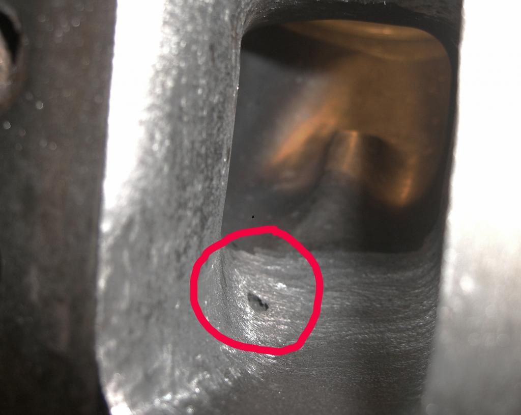
Well today I thought it might be fun to see how far I could go before hitting water. We discussed limitations earlier in this thread. A member on ROP, Bigredolds claimed that he ported his own cast iron heads and raised the roof a full 1/2 inch. I was skeptical about this, and I think Smitty mentioned he was concerned about the rocker pad thickness. I agree there's a lot of force there wanting to pull the bolt that holds the rocker down. If you raise the roof that far I'm sure it will weaken that area. Fortunately most of the porting isn't directly below the rocker pad. If you were to use a shaft type rocker system, it might distribute the forces, and reduce the chance of casting failure. The shaft system is very expensive though. I think they sell for over a thousand dollars. I wanted to see if it was physically possible without hitting a water jacket. I spent about three hours porting, raising the roof a full 1/2". The stock intake port measures 2.30". I ported to 2.80" without hitting any water. When I'm porting, I like to make my transitions as smooth as possible. I started porting as far in as I could reach. Obviously I wasn't going to raise the roof 1/2" up by the bowl, but I was able to keep the roof flat about 1.5" in. I did punch through under the rocker pad bolt hole. I did not remove much material there at all, so it's pretty thin there. This could be repaired by welding or some high temperature epoxy, or you could just use some thread sealer on the rocker bolt & leave the hole. I've seen high end Battens with holes in the roof. This little hole would cause some turbulence, but probably wouldn't hinder flow. I want to have this head flow tested so I will fill it with some epoxy. This is one area everyone should be concerned with if you are drilling and tapping the rocker pad for oversized studs.
CIMG4486.jpg
CIMG4487.jpg
CIMG4494.jpg
CIMG4490.jpg
 March 9th, 2014, 08:24 PM
#404
Seasoned beater pilot.
Join Date: Jan 2007
Location: Chicago
Posts: 5,468
J(Chicago), If you don't like the way I post photos, I apologize. I use photobucket to host my pictures, and like to edit them through that website. I also like the larger size they come up. It allows me to see details that could never be seen in the smaller photos. Rootney posted some porting pictures that I can't see anything, because of the size. When I click on them they stay the same size. I can't tell if his work looks good or not. Let me know if you really want me to post the other way.
So.....you didn't hit water going 1/2" up huh?
March 9th, 2014, 09:00 PM
#405
Registered User
Thread Starter
Join Date: Apr 2010
Posts: 978
No H2O
Nope never hit water. I bet you couldn't get away with this on the SB head. Man it's got my gears turning. I'm thinkin' about going nuts on a pair of C castings I have here. Don't worry, I will finish yours first. I was just playing today. I really must be a slow porter though. Sounds like everybody else can port a set of heads in about 4 hours. To raise the roof this far on a pair would take me 24 hours. Is it worth it? I don't know but I'm real interested in the flow numbers. I'm pretty sure you would have to run a sheet metal intake, or do some serious welding on any production intake. I'm going to do a little bowl work. What do you think I should do with the exhaust port?
March 9th, 2014, 09:28 PM
#406
Seasoned beater pilot.
Join Date: Jan 2007
Location: Chicago
Posts: 5,468
Chambers ate up about 2 hours each, times 8......That's why I hired you, buddy.

I get sick of doing it after 1 head, and that's only 1/3 of the job. Still 1 entire head to go, and then all of the the valve, stud, push rod and geometry work.
At least you get a kick out of it, and enjoy your job. The easiest way to appreciate another guy's hard work, is to trade shoes with him.
I know what you're going through, and respect your efforts on those p.o.s heads I brought you.
March 10th, 2014, 06:34 AM
#407
Registered User
Join Date: May 2013
Location: Newtown CT
Posts: 221
A Test to see if I get the post picture process from J-Chicago.
I think I followed your instructions properly however the result below isn't quite there yet.
Here's an example of what I typed with the 2 $ as in your example;
[$img]https://classicoldsmobile.com/forums/attachment.php?attachmentid=86948&stc=1&d=13944573 63[$/img]
George
March 10th, 2014, 08:10 AM
#408
Registered User
Join Date: May 2013
Location: Newtown CT
Posts: 221
Bear with me.
A Test to see if I get the post picture process from J-Chicago.
I think I followed your instructions properly however the result below isn't quite there yet.
Here's an example of what I typed with the 2 $ as in your example;
[$img]https://classicoldsmobile.com/forums/attachment.php?attachmentid=86948&stc=1&d=13944573 63[$/img]
George
Here are my head photos;
George
Head2_zpsea4c2ce5.jpg
CC2_zps10bea9ce.jpg
Int3_zps1a39a265.jpg
March 10th, 2014, 09:51 AM
#410

Its 1 of 3 things:
1) To help the chamber burn intake gasses more efficiently?
2) Some lost effort for EGR type or injection application for future?
3) Some smart *** GM engineer put a huge divot in there some 40+years ago so questions could ask WTF on an Oldsmobile forum.
I'm going with #1 or #2, depending on what was ate for lunch.
March 10th, 2014, 04:36 PM
#413
Engine Builder
Join Date: Jan 2010
Location: Louisville, ohio
Posts: 552
Yes. The head was bottom up and the machine would stop over it and apply pressure to the casting to hold it in place. Then all 4 chambers had seats cut at the same time. The production line that Oldsmobile had for these engines was state of the art and held accuracy closer than any other engine plant of its time period.
March 10th, 2014, 04:40 PM
#414
Registered User
Join Date: Apr 2012
Location: New Mexico
Posts: 2,972
 March 10th, 2014, 04:48 PM
#415
Engine Builder
Join Date: Jan 2010
Location: Louisville, ohio
Posts: 552
On the head with the 1/2" raised port opening. I doubt it'll flow any more air than it did with the opening at original height. At least not as it sits right now. You've blended it in way too soon to the existing bowl roof for one. A port of that cross section feeding a bowl with significantly smaller cross section is going to be somewhat lazy until its in the upper rpm range. Now when you raise the floor to go with it and reduce the cross section area back to about where you started it will come alive again and may move a little more air. But to get it to really work you need to take it straight in about 3" and blend it in with the back wall of the bowl. That's when your gonna get into the water. Kind of a catch 22 situation. You can do a lot and not help much. Then you do enough to make it really work and end up with undesireable issues.
March 10th, 2014, 05:35 PM
#416
Registered User
Thread Starter
Join Date: Apr 2010
Posts: 978
Raised roof
Yeah I'm sure you're probably right Smitty. I was just playin'. Kind of shocked I didn't hit the water jacket. You are correct about hitting water behind the bowl. Another guy on here did that. I posted a link early on in this thread. I was just experimenting with a junk head. Guess it was a waste of time, but I'm just trying to learn. When we go to have it flow tested, I was going to bring some clay to raise the floor as well. What it really comes down to is how weak is the casting, and modifying an intake would be very time consuming and costly. Is it worth it? I don't think so. I just saw some pictures that Cody posted, and some other builders, raising the roof on the Ebrocks, and filling the floor. Wanted to see if the irons could go that far. If the port was close to the original size, but just raised up, I wonder if you could weld up and relocate the holes on a Victor intake? I think the angle would be way off, but maybe you could fabricate adapter plates and spacers for the lifter valley.
March 11th, 2014, 11:14 AM
#417
Registered User
Join Date: May 2013
Location: Newtown CT
Posts: 221
Dave and all,
I finished 4 intake bowls. Tried to make them symmetrical to each other.
Photo quality is def. a problem. The surface is smoother than it looks.
Looking ahead; 4 more intakes, 8 Exhaust.
Dividers already welded. Plan to fill xover with Resbond ceramic.
Intake runners are smoothed, no major metal removed.
Couple questions here;
1. I wasn't going to port match the intake to the heads. By caliper measure, the intake outlets are smaller than the openings in my heads. Thereby no serious flow impediments (ie. solid walls). I Don't care to raise roof or floor. Comments?
2. I would like to blend the short side radius. Will this be a worthwhile endeavor or a waste of time? How much metal can be removed?
I'm guessing the wall there is around .170 - .200 and was going to remove about .070". Enough? Too Much?
Thanks,
George
BowlBlend1_zpsb7b4e117.jpg
March 11th, 2014, 11:45 AM
#418
G spot head special

I picked these babies up at a swap meet a few years ago, should have left them, true boat anchors! lol
Anyway, One of my guys(quite talented) likes to port heads, so I'm letting him loose on these "G" heads and thought I'd share the progress of how its done.
FYI~ worst heads I ever seen, you'll understand as I post. hahaha


 March 11th, 2014, 12:03 PM
#422

Ran the heads through the sonic tank for 8 hours, still junk.
Cleaned off the intake face, painted some blue dye around the ports, scribed the port layout off my template, ( I raise the template to bottom of port which gives me almost .250 raised ports). we are not going for max effort here, just basic good flowing clean port work that should flow 265-275cfm range with good components and quality valve job.
March 11th, 2014, 12:15 PM
#423

This pic shows how we just Started to clean up the intake port to remove all the rust and start to smooth out the speed bumps.
Clearly this head will need new intake seats, exhaust seats look good for now.
We are going to tumble these in the shot blaster after a quick clean up.
will post as we go...
March 11th, 2014, 12:32 PM
#424
MOTORHEAD
Join Date: Feb 2011
Location: minnesota USA
Posts: 6,604
Have you found an accurate yard stick YET???
amazed at the legs on this tread
amazed at the legs on this tread
Hate to be a naysayer but.......how can you honestly say you are making HP without an accurate flow bench? Same goes for an accurate dyno to test. How are you going to test what you have done without either of these tools? I and a couple other guys found out a few years ago that copying Mondello's tech manual wasn't the best method. Yes the #7s dropped the ET. The next winter took them to a porter who used a flow bench and he made a world of difference.
Track testing can be flawed also. The differences in weather, wind, track conditions at many tracks, wind is a big factor, oh and altitude.
There is a guy on the Kings of Olds Power List that ran his time listed on a day with a -2000 DA. It all makes a difference.
Track testing can be flawed also. The differences in weather, wind, track conditions at many tracks, wind is a big factor, oh and altitude.
There is a guy on the Kings of Olds Power List that ran his time listed on a day with a -2000 DA. It all makes a difference.
 March 11th, 2014, 02:40 PM
#425
Registered User
Thread Starter
Join Date: Apr 2010
Posts: 978
Dave and all,
I finished 4 intake bowls. Tried to make them symmetrical to each other.
Photo quality is def. a problem. The surface is smoother than it looks.
Looking ahead; 4 more intakes, 8 Exhaust.
Dividers already welded. Plan to fill xover with Resbond ceramic.
Intake runners are smoothed, no major metal removed.
Couple questions here;
1. I wasn't going to port match the intake to the heads. By caliper measure, the intake outlets are smaller than the openings in my heads. Thereby no serious flow impediments (ie. solid walls). I Don't care to raise roof or floor. Comments?
2. I would like to blend the short side radius. Will this be a worthwhile endeavor or a waste of time? How much metal can be removed?
I'm guessing the wall there is around .170 - .200 and was going to remove about .070". Enough? Too Much?
Thanks,
George

Brad do you guys magnaflux or pressure test the heads before doing all that port work? That's a pretty cool template. I just move the gasket up to mark.
Brad, I did have some other questions for you earlier in this thread if you have time to look back to my response. Keep up the good work guys.
March 11th, 2014, 02:45 PM
#426
Registered User
Join Date: May 2013
Location: Newtown CT
Posts: 221
George, I wouldn't bother with match porting the intake. From everything I've heard and read, the biggest performance gains come from the bowl work and a good quality valve job. Nice progress. You're plugging right along.
Brad do you guys magnaflux or pressure test the heads before doing all that port work? That's a pretty cool template. I just move the gasket up to mark.
Brad, I did have some other questions for you earlier in this thread if you have time to look back to my response. Keep up the good work guys.
Brad do you guys magnaflux or pressure test the heads before doing all that port work? That's a pretty cool template. I just move the gasket up to mark.
Brad, I did have some other questions for you earlier in this thread if you have time to look back to my response. Keep up the good work guys.
Could either of you offer advice for my question #2 above ?
Thanks,
George
March 11th, 2014, 05:41 PM
#429
Engine Builder
Join Date: Jan 2010
Location: Louisville, ohio
Posts: 552
I mag everything before starting. If it's a major port job it gets pressure tested afterwards.
2. I would like to blend the short side radius. Will this be a worthwhile endeavor or a waste of time? How much metal can be removed?
I'm guessing the wall there is around .170 - .200 and was going to remove about .070". Enough? Too Much?
Lay it down as much as you feel comfortable. .070 is safe number that will not get you into trouble and blend it in to the top of the short turn . Open the bowls under the seat up to 88-90% of the valve diameter.
March 11th, 2014, 06:14 PM
#430
Registered User
Join Date: May 2013
Location: Newtown CT
Posts: 221
I mag everything before starting. If it's a major port job it gets pressure tested afterwards.
2. I would like to blend the short side radius. Will this be a worthwhile endeavor or a waste of time? How much metal can be removed?
I'm guessing the wall there is around .170 - .200 and was going to remove about .070". Enough? Too Much?
Lay it down as much as you feel comfortable. .070 is safe number that will not get you into trouble and blend it in to the top of the short turn . Open the bowls under the seat up to 88-90% of the valve diameter.
2. I would like to blend the short side radius. Will this be a worthwhile endeavor or a waste of time? How much metal can be removed?
I'm guessing the wall there is around .170 - .200 and was going to remove about .070". Enough? Too Much?
Lay it down as much as you feel comfortable. .070 is safe number that will not get you into trouble and blend it in to the top of the short turn . Open the bowls under the seat up to 88-90% of the valve diameter.
Thanks.
Just as a point of reference, what might you consider a "risky" amount to take off?
And,
about the 88-90%, is there a method to measure it? The bowl directly under the valve set is not symmetrical.
Regards,
George
March 11th, 2014, 06:20 PM
#431
Engine Builder
Join Date: Jan 2010
Location: Louisville, ohio
Posts: 552
Risky would be more than 1/8" off the middle of the radius and blended each way to seat and floor.
March 13th, 2014, 12:43 AM
#433
I'm thinking about doing an exchange program on GM iron and aluminum Edelbrock heads?
If your like me, you have old heads laying around, so Send in your good old head cores and receive ported replacement heads in exchange?
I've exchanged a few sets here recently and thinking if there is enough interest I could start a program?
If your like me, you have old heads laying around, so Send in your good old head cores and receive ported replacement heads in exchange?
I've exchanged a few sets here recently and thinking if there is enough interest I could start a program?
March 13th, 2014, 05:25 AM
#435
Registered User
Thread Starter
Join Date: Apr 2010
Posts: 978
My questions
This was quoted from my response to you Brad. I cut out a lot to make it easier to view my questions-
Originally Posted by Wise Performance
~Valve sizes~ This is a good one, most people think you need the biggest exhaust valves you can fit, well I'm hear to debunk that myth with some fact.
The surface area of a 1.60 valve has enough area to support 1200+ HP N/A, and there is no need to go bigger. Now take that 1.60 valve and measure YOUR specific bore and order the largest intake valve you can fit in there without shrouding and thats the max you have to work with.
I have heard this before. It does make sense. I know there's a formula for determining what size exhaust valve is needed to flow for a corresponding intake valve. It seems like this is pretty standard for the top engine builders to stuff the biggest intake valve you can fit in there, and then put a tiny exhaust valve in until it almost touches. I still don't understand how you get around the shrouding issue on the intake side of the chamber. Do you open it up out to the gasket mating point?
~BBO irons finished vs.E-brocks~ Good question, depends on budget and overall desire. Iron have the capibility to make great power in the right hands, e-brocks and like are basically aluminum versions of iron with a better chamber and flow a little better, much easier to work with and way lighter.
I think you misunderstood my question about Cast iron vs E-brocks. I was just curious of your opinion of stock cast irons with a good vave job vs E-brocks out of the box. Let's say same size valves.
~Milling irons~ IDK, I take off only whats needed for desired CR or to achieve correct RA.
The reason I asked this was because my machinist milled a set of BB heads .060, and the customer had head gasket sealing issues. I didn't get all the details, but he felt the head deck was more prone to warpage. He recomended not milling more than .050"
~Valve guides~ Bronze liners or bronze guides are usually what I use in irons with SS valves.
The reason I asked about this was because Jeremy's heads have a broken guide. I purchased a set of steel replacement guides from Rock Auto. They were dirt cheap. I'm considering having all the guides replaced. Most of the cost is in the labor. I'm not opposed to using bronze guides. They aren't that expensive. I was under the impression bronze guides were preffered for race aplication. These heads will see hard street usage and some track time. Which do you guys think will last longer?
Brad @ WPE
Brad, some of the guys on here have said this thread is not a good place to advertise porting services. I really don't have a problem with it. I'm glad that you have taken your time to share information to the home porters. That's what this thread is all about. I think the exchange idea is pretty good, as long as you get good cores, and can find enough interest. The only problem I see is, not everyone needs a max effort port job on cast iron heads. Maybe you could offer different levels or "stages" like some of the other vendors do. Shipping these boat anchors back and forth will probably be the deal breaker for most of the cheap bastard Olds crowd. After all what's a good core set of heads worth, maybe $200? I think it costs something like $120 to ship a pair.
With that being said, I think you should start your own thread about your exchange idea, to see if there would be enough interest.
By the way if you were going to do a max effort exhaust port, what exactly would you do? How far would you go? I want to experiment on the junk head to see how far I can go, then have it flow tested to see if there's significant improvement. Please keep posting photos with your porting progress, and flow numbers seem to help spark interest.
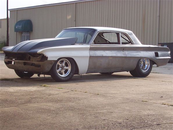
Still waiting for the UFO thread. Man I do like what you've done to that car. I never cared for the body style before, but now I think it looks pretty cool. I must be getting old.
Originally Posted by Wise Performance
~Valve sizes~ This is a good one, most people think you need the biggest exhaust valves you can fit, well I'm hear to debunk that myth with some fact.
The surface area of a 1.60 valve has enough area to support 1200+ HP N/A, and there is no need to go bigger. Now take that 1.60 valve and measure YOUR specific bore and order the largest intake valve you can fit in there without shrouding and thats the max you have to work with.
I have heard this before. It does make sense. I know there's a formula for determining what size exhaust valve is needed to flow for a corresponding intake valve. It seems like this is pretty standard for the top engine builders to stuff the biggest intake valve you can fit in there, and then put a tiny exhaust valve in until it almost touches. I still don't understand how you get around the shrouding issue on the intake side of the chamber. Do you open it up out to the gasket mating point?
~BBO irons finished vs.E-brocks~ Good question, depends on budget and overall desire. Iron have the capibility to make great power in the right hands, e-brocks and like are basically aluminum versions of iron with a better chamber and flow a little better, much easier to work with and way lighter.
I think you misunderstood my question about Cast iron vs E-brocks. I was just curious of your opinion of stock cast irons with a good vave job vs E-brocks out of the box. Let's say same size valves.
~Milling irons~ IDK, I take off only whats needed for desired CR or to achieve correct RA.
The reason I asked this was because my machinist milled a set of BB heads .060, and the customer had head gasket sealing issues. I didn't get all the details, but he felt the head deck was more prone to warpage. He recomended not milling more than .050"
~Valve guides~ Bronze liners or bronze guides are usually what I use in irons with SS valves.
The reason I asked about this was because Jeremy's heads have a broken guide. I purchased a set of steel replacement guides from Rock Auto. They were dirt cheap. I'm considering having all the guides replaced. Most of the cost is in the labor. I'm not opposed to using bronze guides. They aren't that expensive. I was under the impression bronze guides were preffered for race aplication. These heads will see hard street usage and some track time. Which do you guys think will last longer?
Brad @ WPE
Brad, some of the guys on here have said this thread is not a good place to advertise porting services. I really don't have a problem with it. I'm glad that you have taken your time to share information to the home porters. That's what this thread is all about. I think the exchange idea is pretty good, as long as you get good cores, and can find enough interest. The only problem I see is, not everyone needs a max effort port job on cast iron heads. Maybe you could offer different levels or "stages" like some of the other vendors do. Shipping these boat anchors back and forth will probably be the deal breaker for most of the cheap bastard Olds crowd. After all what's a good core set of heads worth, maybe $200? I think it costs something like $120 to ship a pair.
With that being said, I think you should start your own thread about your exchange idea, to see if there would be enough interest.
By the way if you were going to do a max effort exhaust port, what exactly would you do? How far would you go? I want to experiment on the junk head to see how far I can go, then have it flow tested to see if there's significant improvement. Please keep posting photos with your porting progress, and flow numbers seem to help spark interest.
Still waiting for the UFO thread. Man I do like what you've done to that car. I never cared for the body style before, but now I think it looks pretty cool. I must be getting old.
 March 13th, 2014, 10:31 AM
#436
As far as exchange, I really don't think 265-275cfm on irons is max effort at all, was never trying. My goals are basic quality work with quality components.
I'm just looking to keep my help busy, there is no $$$ in porting iron Olds heads, break even at best. I think Any head porter will agree.
Back in the 80's we ported irons because thats all what was available, we made power back then, (flow benches were only for Prostocks). Now today most every head is flowed on a bench and CNC work is common place, so I applaud those who have the notion to port by hand and offer my knowledge/service if it helps.
I mostly agree with Smitty on his practices for porting/engine building, his comments are usually spot on with my thoughts.
I would love to post current detailed pics of all my projects, but just don't have time to do it like you do, so it will be short and to the point. lol
Now if you really want to start a S&%T storm, I'll post flow numbers, and dyno sheets! I don't have the time or energy to deal with it right now. lol
Last edited by Wise Performance; March 13th, 2014 at 11:39 AM.
March 18th, 2014, 10:43 PM
#437
Registered User
Thread Starter
Join Date: Apr 2010
Posts: 978
CC the Combustion
Sorry guys but this is going to be a rather long post. I think I will break it up into a couple sections. First of all, knowing how many CCs the combustion chamber is will be crucial to establishing your compression ratio. As we all know, the higher the ratio, the more efficient the engine will perform. Also the higher the compression ratio the less streetable. For most guys streetable equates to the ability to run pump gas. Most engine builders will agree that 10.5:1 is about the highest you can safely go. Some guys will say 11:1 is still capable of running pump gas. It all comes down to how well tuned you can make everything from fuel delivery to timing. I really don't want to get into a debate here about what ratio everybody thinks is still streetable. I am making these statements about a generalization, of what the industry considers as runnable on pump gas. Aluminum heads can go slightly higher. With that being said, the earlier high performance Olds engines had an advertised compression ratio of 10.25:1, and I think the old leaded fuel helped with lubrication of the valve train. After 1972 the compression ratios started to drop because of emission standards. These pages were taken from Mondello's Technical Reference Manual-
001.jpg
001.jpg
March 19th, 2014, 01:38 PM
#439
Registered User
Thread Starter
Join Date: Apr 2010
Posts: 978
I have them & tried posting last night, but photo bucket was jackin' with me. Kept posting them up side down. I will try again tonight. I am going to show a how to on CC-ing the combustion chamber. I was real tired.
March 19th, 2014, 06:42 PM
#440
Registered User
Thread Starter
Join Date: Apr 2010
Posts: 978
BBOldsCylinderheads001-1.jpg
Hope it works this time. Well guys, last night I measured the combustion chamber volume on Coppercutlass' #6 SB heads. These heads were already milled. My good friend Dane Luling from Mild to Wild Racing let me borrow his graduated cylinder, and described the procedure. So I'm going to try to explain the process here. The first step is to level the cylinder head front to back and side to side. This is important to get all the air out when you're filling the chamber. The cylinder is also supposed to be level, but that's not as important. It's just so the fluid level line is straight.
CIMG4506.jpg
The cylinder needs to be filled to the zero mark with colored fluid. I had some washer solvent handy so it worked just fine for me.
CIMG4512.jpg
Next you need to put a little grease on the valves around the seat area. You don't need to install them with the springs and retainers. The grease will seal them up just fine. Now smear a little around the outer edge of the combustion chamber. I used synthetic brake grease because it had a nice applicator brush.
CIMG4509.jpg
Now don't be a dummy like me and forget to put a spark plug in. This piece of plexiglass was a little small, but it worked OK. It has one hole for the fluid to enter and another small hole for the air to come out.
CIMG4510.jpg
This picture was taken as I was filling-
CIMG4513.jpg
This chamber held 67 ML of fluid. 1 Milliliter = 1 CC. So this chamber is 67 CCs. According to the chart this head started out at 70CC. We are very fortunate with our Olds heads to have a measurable reference point to determine if the head was milled. Measure between the end, lower head bolt boss and the deck surface of the head. The average stock measurement for OEM head is 2.200"-2.220". These # 6 heads measured 2.170" so most likely they were shaved .030" or slightly more.
There's a formula for how many CCs will be reduced for every .010" you shave off the head. I will see if I can find it so we can determine how many CCs were added when I polished the chamber. Here's a link to an online compression ratio calculator-
https://www.rbracing-rsr.com/compstaticcalc.html
Here's the formula for calculating compression ratio-
36539bdb-bcc5-4db5-9e9d-7c285f9cf5e9.jpg
Last edited by 67 Cutlass Freak; March 19th, 2014 at 06:46 PM.


