Classic Auto Air Upgrade Kit for 1968-72 Cutlass
 August 4th, 2011, 05:35 PM
#1
Registered User
Thread Starter
Join Date: Jan 2008
Location: Wichita, KS
Posts: 241
Classic Auto Air Upgrade Kit for 1968-72 Cutlass
I decided to upgrade the A/C system in my 1970 Cutlass S to a new R134a system. The original system has leaked for more than 25 years despite many attempts to fix it; we finally stopped recharging it about 15 years ago. The compressor hasn't been run in at least 10 years. When I disassembled the system last year I didn't bother to preserve the various parts, so one way or another it was going to be a complete redo.
Rather than refurbish the original parts, I ordered the engine compartment upgrade kit from Classic Auto Air. It consists of: new rotary (Sanden) compressor with engine mount, new hoses, new condenser, new receiver-drier. A new POA valve, expansion valve, and evaporator were separate purchases. They say it's all designed to fit right into the engine compartment without modification.
I've seen other folks talking about A/C system upgrades on this website recently, so I thought I 'd post some pictures of the kit and show how it compares to my original parts. It looks like the condenser and evaporator are fairly close matches to the originals, at least in terms of overall size, connection locations, and the shape of the evaporator upper tube. The compressor is a glaring departure from original, but I made peace with that before I ordered it (took me a while to get there though!).
It may take a while to get the new system installed and running, but I'll post an update when I do.
Last edited by O's_Car; August 22nd, 2011 at 09:22 PM. Reason: It's a receiver-drier, not an accumulator!
 August 4th, 2011, 05:40 PM
#2
Registered User
Thread Starter
Join Date: Jan 2008
Location: Wichita, KS
Posts: 241
More pictures. The compressor mount attaches with 3 bolts through the front of the passenger-side cylinder head. It has adjustment provisions for different drive belt locations. The evaporator looks pretty similar to original. It has mounting tabs like the original, they're just not bent out yet.
August 4th, 2011, 05:45 PM
#3
Registered User
Thread Starter
Join Date: Jan 2008
Location: Wichita, KS
Posts: 241
Even more pictures. The plumbing connections and mounting locations on the new condenser appear to be in the same place as original. The cooling fin design is completely different: supposedly this is key to good R134a system performance.
 August 5th, 2011, 09:00 AM
#5
Registered User
Join Date: Feb 2008
Location: Plano, TX
Posts: 11,798
Did you read the instructions yet?? Seems as if they really want you to. 
Is that condenser a parallel flow? I do not see tubes on the side. THAT is the true key to 134 efficiency.
They also sell a regular style replacement with fins closer together. Looks more stock but not as efficient.
I want more info on that POA valve, as it looks like a real POA!!
The cycling clutch switch valve usually comes with those sanden units - the one that have the big switch sticking up.
Did you notice your new evap is wider than the original? Hope it fits the box okay (it should)...
Good thread - keep us updated!
August 6th, 2011, 10:01 PM
#6
Registered User
Thread Starter
Join Date: Jan 2008
Location: Wichita, KS
Posts: 241
Did a test fit of the compressor bracket yesterday (see photos below) - it lined right up with the threaded holes in the cylinder head. I'll get the bracket powdercoated before final installation.
We hit 113 here earlier this week. Before I tore down the Cutlass these hot summer days made for short cruises. I'm looking forward to a long comfortable drive when the car gets put back together.
Those warnings are everywhere! I did look over the instructions - they're a little sketchy in places, but I think I can figure it out. Classic Auto Air encourages customers to call them with questions, I've already started a list.
The condenser is a parallel flow "high performance" type, they emphasized that in the sales literature they sent me. And that is a real rebuilt/recalibrated POA valve. They do those on a core exchange basis: they'll refund me $50 if I send them my old one. I could have had them recalibrate mine instead, but I thought the turn-around time wouldn't fit my schedule. I don't know about a cycling clutch switch, they didn't mention anything about it. I'll add that to my list of questions.
I measured the evaporators this morning: the new one is about the same thickness (3 5/8 inches) but is about 1/4 inch wider and 1/4 inch shorter than the original. Seems like that should fit, I'll update when I assemble it.
Before I tore down the Cutlass these hot summer days made for short cruises. I'm looking forward to a long comfortable drive when the car gets put back together.Did you read the instructions yet?? Seems as if they really want you to.
Is that condenser a parallel flow? I do not see tubes on the side. THAT is the true key to 134 efficiency.
They also sell a regular style replacement with fins closer together. Looks more stock but not as efficient.
I want more info on that POA valve, as it looks like a real POA!!
The cycling clutch switch valve usually comes with those sanden units - the one that have the big switch sticking up.
Did you notice your new evap is wider than the original? Hope it fits the box okay (it should)...
The condenser is a parallel flow "high performance" type, they emphasized that in the sales literature they sent me. And that is a real rebuilt/recalibrated POA valve. They do those on a core exchange basis: they'll refund me $50 if I send them my old one. I could have had them recalibrate mine instead, but I thought the turn-around time wouldn't fit my schedule. I don't know about a cycling clutch switch, they didn't mention anything about it. I'll add that to my list of questions.
I measured the evaporators this morning: the new one is about the same thickness (3 5/8 inches) but is about 1/4 inch wider and 1/4 inch shorter than the original. Seems like that should fit, I'll update when I assemble it.
Last edited by O's_Car; August 6th, 2011 at 10:07 PM.
August 7th, 2011, 02:43 PM
#7
Registered User
Join Date: Jul 2009
Location: Brooklyn, NY
Posts: 1,941
Looks like an easy kit to install. How much is this kit? I also have a 70 Cutlass and i would like to install an aftermarket a/c. Does the new bracket has to bolt onto the bottom cylinder head bolt with the stud sticking out? My cylinder heads is bolted down with ARP studs so i was wondering with the kit that you have does it bolt to that stud?
August 7th, 2011, 08:34 PM
#8
Registered User
Thread Starter
Join Date: Jan 2008
Location: Wichita, KS
Posts: 241
Looks like an easy kit to install. How much is this kit? I also have a 70 Cutlass and i would like to install an aftermarket a/c. Does the new bracket has to bolt onto the bottom cylinder head bolt with the stud sticking out? My cylinder heads is bolted down with ARP studs so i was wondering with the kit that you have does it bolt to that stud?
Their website is www.classicautoair.com. For some reason they don't list the Cutlass kit in their literature, but if you contact them they'll send you the details. Their "Factory Air Conditioning Parts & Service Catalog" lists the prices of all the items they sell.
August 18th, 2011, 05:03 PM
#9
Registered User
Thread Starter
Join Date: Jan 2008
Location: Wichita, KS
Posts: 241
I did a test fit of the new evaporator in the case yesterday. As I mentioned in an earlier post the new evaporator is a little wider and a little shorter than the original. Being wider makes it a bit snug depth-wise in the case but it's manageable; being shorter means there's a bit of an air gap at the top and bottom but again it's manageable. The biggest problem is the new seal I installed around the evaporator opening in the case, it's about half as thick as the original which leaves the evaporator a little loose sideways and exagerates the top and bottom air gaps. I'm going to get some foam weatherstrip at the hardware store and double up around the opening. That should eliminate the sideways looseness and air gaps. Pictures to follow.
August 18th, 2011, 07:19 PM
#10
Registered User
Join Date: Feb 2008
Location: Plano, TX
Posts: 11,798
I was hoping to have an original core restored but they (CAA) pressure tested and it failed. So now I have to buy that same one you have. However, the four seasons ones from the chain stores fit like total crap so the one you got is the best available replacement I have come across so far...
August 18th, 2011, 07:43 PM
#11
Registered User

Join Date: May 2009
Location: USA
Posts: 2,200
I just completely gutted my stock AC system inside and out.
I'm going to be putting it up for sale this week.
I've been eyeballing Classic Auto Air and Vintage Air options.
I'm figuring $1600-$2000 range most likely. That's 2012's project though.
That's to mate up to the new LSX motor.
Nice thing about Classic is it bolts up to an existing system and controller.
Plus it's not a sealed box, so it can be serviced. Vintage is sealed.
August 19th, 2011, 09:10 PM
#12
Registered User
Thread Starter
Join Date: Jan 2008
Location: Wichita, KS
Posts: 241
The pictures below give an idea of the fit. In the last one you can just make out the air gap at the inner corner of the seal. I think a little maneuvering of the evaporator will eliminate most of that.
I just completely gutted my stock AC system inside and out.
I'm going to be putting it up for sale this week.
I've been eyeballing Classic Auto Air and Vintage Air options.
I'm figuring $1600-$2000 range most likely. That's 2012's project though.
That's to mate up to the new LSX motor.
I'm going to be putting it up for sale this week.
I've been eyeballing Classic Auto Air and Vintage Air options.
I'm figuring $1600-$2000 range most likely. That's 2012's project though.
That's to mate up to the new LSX motor.
August 20th, 2011, 08:31 AM
#13
Registered User

Join Date: Nov 2010
Location: St Louis, MO
Posts: 904
I put a CAA universal kit in my LS powered 72 442. Directions were a bit sparse, but they do have geat cutomer/technical support.
BTW, I'm guessing your compressor binary switch is on the accumulator.
BTW, I'm guessing your compressor binary switch is on the accumulator.
August 20th, 2011, 09:02 AM
#14
Connoisseur d'Junque
Join Date: Sep 2010
Location: The Hudson Valley
Posts: 21,183
Clutch cycling and POA are an either / or pair.
EITHER you've got a POA
OR you've got a pressure-cycling clutch.
They are two DIFFERENT ways of modulating the compressor in light of load, demand, temperature, and engine speed (auto A/C has to account for a lot of things your home A/C does not).
A POA varies the amount of pressure in the system, with the compressor constantly on, but running at varying loads, depending on the pressure set by the POA.
A cycled clutch tuns the compressor on FULL until it's built up enough pressure, then turns it off until the pressure drops again.
- Eric
August 20th, 2011, 04:22 PM
#16
Registered User
Join Date: Feb 2008
Location: Plano, TX
Posts: 11,798
Yep, one system does not use both of them.
The big A6 compressor does not like being cycled every minute or so, so if using an A6, a POA is preferred. The sanden styles are designed to be cycled.
Therefore under hot conditions, evap pressure would be way above that and the POA is wide open allowing max freon flow.
After the car cools down or under cooler conditions, the evap pressure drops. If the evap pressure starts to drop below 28, the POA starts to close, blocking the flow of freon until the pressure stays over 28.
Yes. Now whether they will hold up to constant operation, I do not know - a good question for the CAA guys or Sanden itself (if you can get an answer from them.)
August 20th, 2011, 10:42 PM
#17
Registered User
Thread Starter
Join Date: Jan 2008
Location: Wichita, KS
Posts: 241
Eric & Rob, thanks for the clarifications! I'm definitely not fully educated on A/C system operations so I appreciate the information. I'll ask about the constant operation of the compressor. It seems CAA would have accounted for that before offering the kit...
August 20th, 2011, 11:23 PM
#18
Registered User
Join Date: Nov 2010
Location: St Louis, MO
Posts: 904
1st post, middle pic, guessing that cylinder in the center is an accumulator?
No accumulator on the stock 72 setup. Only the POA and expansion valve. Compressor stays on as long as the AC is on.
Yep, one does not use bot of them.
The big A6 compressor does not being cycled every minute or so, so if using an A6, a POA is preferred. The sanden styles are designed to be cycled.
The POA is a glorified pressure regulator. It is designed to keep the evaporator pressure no less than 28psi with R12. IF the pressure dropped below that, the evap would freeze up.
Therefore under hot conditions, evap pressure would be way above that and the POA is wide open allowing max freon flow.
After the car cools down or under cooler conditions, the evap pressure drops. If the evap pressure starts to drop below 28, the POA starts to close, blocking the flow of freon until the pressure stays over 28.
Yes. Now whether they will hold up to constant operation, I do not know - a good question for the CAA guys or Sanden itself (if you can get an answer from them.)
August 21st, 2011, 06:58 AM
#19
Registered User
Join Date: Feb 2008
Location: Plano, TX
Posts: 11,798
Silver one is the POA - mounts near evap.
Later model systems combine the filer/dryer, the orifice tube (replaces POA), and low pressure switch (to cycle the compressor) all into one unit called the accumulator, which is often mounted between the evap and compressor. I believe it got its name because it accumulated the excess liquid freon, too.
August 21st, 2011, 07:15 AM
#20
Connoisseur d'Junque
Join Date: Sep 2010
Location: The Hudson Valley
Posts: 21,183
Although the accumulator and the receiver / drier seem to do the same thing (hold liquid freon and a desiccant to remove water), they are not the same part.
A receiver / drier is placed after the condenser and before the expansion valve, in the high-pressure liquid line (attached to the condenser on the radiator support in our cars), while an accumulator is placed after the evaporator in the low-pressure vapor line, between the evaporator and the condenser, where it holds onto liquid freon that comes out of the evaporator so that it doesn't get to the compressor, which would be bad (it is attached to the evaporator housing).
Receiver / Drier:

Accumulator:
- Eric
 August 21st, 2011, 11:28 AM
#22
Registered User
Thread Starter
Join Date: Jan 2008
Location: Wichita, KS
Posts: 241
Got the evaporator installed yesterday and sealed up the case. The extra layer of weatherstrip helped hold the evaporator in place and close off the air gaps. Also installed the new POA valve.
I started to install the new expansion valve, but the capillary tube and equalizer lines are way longer than the original. I looped them around to take up the extra length, but I'm not sure if that'll affect their function. Yet another question for the CAA guys on Monday.
I started to install the new expansion valve, but the capillary tube and equalizer lines are way longer than the original. I looped them around to take up the extra length, but I'm not sure if that'll affect their function. Yet another question for the CAA guys on Monday.
August 21st, 2011, 04:50 PM
#23
Registered User
Join Date: Feb 2008
Location: Plano, TX
Posts: 11,798
Looks good so far. I get to build up my evap box late this week when the evap comes in.
Most guys seem to wind up the excess tubing on a 1"-1.5" spool (or socket) to make them into neat spirals. Makes for good looks and keeps them out of the way when doing mainanence or cleaning.
As long as you do not pinch them so where it cuts off the internal flow, they will be fine.
BTW, did you bend out the evaporator mounting tabs before sealing it the box? What did you seal the two box halves together with?
And heaven forbid, Where are your Harrison stickers?
August 22nd, 2011, 09:13 PM
#24
Registered User
Thread Starter
Join Date: Jan 2008
Location: Wichita, KS
Posts: 241
...Most guys seem to wind up the excess tubing on a 1"-1.5" spool (or socket) to make them into neat spirals. Makes for good looks and keeps them out of the way when doing mainanence or cleaning.
As long as you do not pinch them so where it cuts off the internal flow, they will be fine.
BTW, did you bend out the evaporator mounting tabs before sealing it the box? What did you seal the two box halves together with?
And heaven forbid, Where are your Harrison stickers?
As long as you do not pinch them so where it cuts off the internal flow, they will be fine.
BTW, did you bend out the evaporator mounting tabs before sealing it the box? What did you seal the two box halves together with?
And heaven forbid, Where are your Harrison stickers?
I did bend out the front tabs on the evaporator, like the original. I sealed the two case halves with some butyl strip seal I got from the body shop. They said it's the same stuff the factory used, or close to it. I just rolled it out into a thin line and stuck it in the groove in the larger case half (see pictures below). I got a slight bit of squeeze out at the seams when I tightened down the screws, so I think that was the right amount.
And never fear, I do have a repro Harrison sticker to put on!
The original evaporator had one stuck to the back (see pictures below), but I'm not replacing that one (who's gonna see it?). I found another one on the outside of the case under the heater core hoses.
Last edited by O's_Car; August 22nd, 2011 at 09:30 PM.
August 22nd, 2011, 11:33 PM
#25
Registered User
Join Date: May 2009
Location: USA
Posts: 2,200
I've got all my 442's factory AC/Heat components I've been thinking of putting up for sale.
So after seeing this thread how he's merging pieces, i want to know what I should keep .....if anything.
August 23rd, 2011, 04:41 AM
#26
Registered User
Join Date: Nov 2010
Location: St Louis, MO
Posts: 904
I can do that.
Gary, would you by chance be willing to share that info and pics of the install if you got them in the Non-Olds section with a write up??
I've got all my 442's factory AC/Heat components I've been thinking of putting up for sale.
So after seeing this thread how he's merging pieces, i want to know what I should keep .....if anything.
I've got all my 442's factory AC/Heat components I've been thinking of putting up for sale.
So after seeing this thread how he's merging pieces, i want to know what I should keep .....if anything.
August 23rd, 2011, 05:29 AM
#27
Registered User
Join Date: Feb 2008
Location: Plano, TX
Posts: 11,798
How well did the small lines connect to the POA valve? I have heard rumors of the O-rings included witht the "GM O-ring kit" not being just the right size for those small lines and would not seat properly. Any issues?
Oh come on...  You have to impress the tech who takes it apart later!
 ")
Just peel the old sticker off, clean it, flatten it in a big book for a while, then adhere to the new core with epoxy - easy!
Okay, I have become a bit **** during all this resto work...
If all possible I would recommend you keep and use your existing evap box assembly to keep the system mods and underdash work to a minimum. Pressure test the core for leaks and clean it all up. However, clearance to the evap box may be an issue with the LS engine. A newer sanden compressor would look right at home on the LS. Add a parallel flow condenser and you will be on the right track.
You have to impress the tech who takes it apart later! Just peel the old sticker off, clean it, flatten it in a big book for a while, then adhere to the new core with epoxy - easy!
Okay, I have become a bit **** during all this resto work...
If all possible I would recommend you keep and use your existing evap box assembly to keep the system mods and underdash work to a minimum. Pressure test the core for leaks and clean it all up. However, clearance to the evap box may be an issue with the LS engine. A newer sanden compressor would look right at home on the LS. Add a parallel flow condenser and you will be on the right track.
August 23rd, 2011, 07:59 PM
#28
Registered User
Thread Starter
Join Date: Jan 2008
Location: Wichita, KS
Posts: 241
I didn't have any issues. The o-rings fit snugly over the ends of the lines and appeared to compress correctly into the seats in the fittings. The kit has 5 different sizes of o-rings, plus there were o-rings already installed over each tube end and inside each fitting (had to make sure I wasn't doubling up). I lubed them up with the supplied oil before making the connections.
August 28th, 2011, 12:35 PM
#29
Registered User
Thread Starter
Join Date: Jan 2008
Location: Wichita, KS
Posts: 241
I finished up the evaporator case this week: tidied up the expansion valve lines, clamped the capillary tube to the evaporator suction line and wrapped it with cork tape, and tightened all the plumbing connections. I cleaned up and re-installed the blower resistor, sealed with a thin bead of butyl tape. I also installed a new blower motor with a new flange seal. I had the original fan media-blasted and gave it a light coat of paint before attaching it to the motor. Then I took the evaporator case, heater case, and air inlet valve to the body shop and installed them to the firewall. I used a good bead of butyl tape around the edges of the evaporator case to seal it to the firewall, the heater case was sealed by the new insulation pad. I used some household weatherstrip to seal the air inlet valve to the kick panel. Some pre-installation pictures are included below, but I put the installed pictures in my "Green Mo-sheen" thread:
https://classicoldsmobile.com/forums/316450-post91.html
https://classicoldsmobile.com/forums/316451-post92.html
While I was there I installed the new compressor and brackets to the engine. The brackets got powdercoated satin black like the other accessory brackets, and I painted the spacers to match the engine (I had some leftover blue engine paint). Note that the new compressor bracket doesn't pick up that special head bolt like the factory bracket, so I re-installed the ARP head bolt at that location. Once the condenser is installed I'll route the new hoses and have the end fittings clamped on.
March 17th, 2013, 06:24 PM
#31
Registered User
Join Date: Jan 2009
Location: Harrison, Michigan
Posts: 4,727
Oskar, saw your reply to my question on your green mosheen thread. Thanks, I think you have done a great job!!! I know how life gets in the way of our projects. I am in the middle of restoring my a/c system and look at yours and Rob's threads all the time. I started a thread on my job titled "71 cutlass a/c restoration" under major builds and restorations if you want to look at. Thanks,Greg
December 17th, 2014, 07:35 PM
#32
Registered User
Thread Starter
Join Date: Jan 2008
Location: Wichita, KS
Posts: 241
Overdue Update
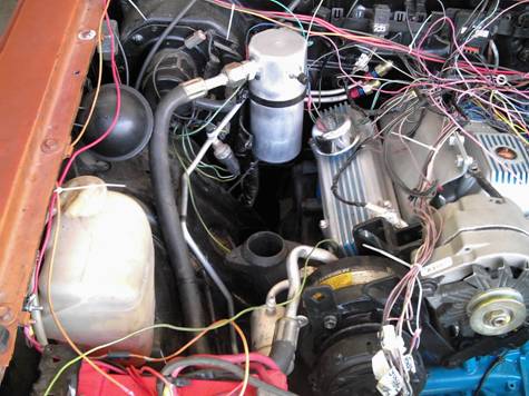
Well it's been over 3 years since I last posted to this thread, when I had installed the evaporator case, heater case, air inlet valve, and compressor in my Cutlass. Now doing my best Seinfeld imitation, "yadda yadda yadda", the A/C system is finished! Below are some pictures showing the finished product. Not the prettiest thing you've ever seen, but it works.
I made a mistake with the suction hose - the one running from the POA valve to the compressor. I originally routed it under the compressor, and had the hose trimmed and the fitting crimped on accordingly. I later realized the instructions said to route this hose over the compressor. When I did this, the hose was too long and sagged into contact with the compressor pulley. I thought about ordering another fitting and cutting the hose shorter, but instead I just fabbed up a little spacer to keep the hose away from the pulley.
I also had some difficulty with the drive belt. A while back I test fitted a bunch of belts until I found one that would just slip over all the pulleys. When I later tried to install it permanently, somehow I couldn't get it to slip on! I eventually had to get the next longer length belt (1 inch longer), and as you can see from the last picture I'm about at the limit of adjustment on the compressor. Then I found that the drive belt was just contacting the lower radiator hose, and I had to adjust the hose to provide more clearance. This thing fought me all the way, but eventually I emerged victorious.
I took the car to a local shop to have the system evacuated and charged, and took it out for a drive on a hot day to test it. For the first time in about a quarter century, the Cutlass was nice and cool inside! The fittings on either end of the suction hose iced up pretty good and it dripped a lot of water on the ground - don't know if that's good or not. I'll have to wait until next summer to test it further.
December 17th, 2014, 09:10 PM
#33
Registered User
Join Date: Jan 2013
Location: Wichita, KS
Posts: 44
Thanks for updating this Oskar. CAAs instructions are not super clear. The AC belt is supposed to run on the outer (most forward) pulley groove. To make this happen you have to put the 1" spacer in front of the hinge piece. So CAAs instructions are wrong. I too had to buy a much longer belt than my stock one (Stock is 60.5", I had to go with a 63&5/8" as 62&5/8" was still too short. I think a 63.0" would work and may continue to look. I did some research on Butyl tape and found some at the parts store I do a lot of business with. I don't understand why the suction line needs to go forward before it goes back to the POA. It would be so much cleaner if it could just go straight back. We need to get together to check out each others cars. I'm usually home evenings and weekends (when its too cold to play golf). Give me a call sometime. I think I left my cell in the PM I sent you. Thanks again, Joe
December 27th, 2014, 04:25 PM
#34
Registered User
Join Date: Jan 2009
Location: Harrison, Michigan
Posts: 4,727
Glad to see you got it going Oskar. Mine is together now also but not real happy with it. I used the regular factory A6 compressor, all other new but factory style parts converted to R134A. I got it done in 2013 and went to the Olds Nationals in Springfield. I had problems but planned to sort them out in 2014. Well the summer of '14 was so cool that I never used it. I kinda wish I went to the smaller compressor like you did. Well hopefully I will get it tweeked next summer.
December 30th, 2014, 09:07 AM
#35
Registered User
Join Date: Jan 2013
Location: Wichita, KS
Posts: 44
Got my CAA kit installed
Finished my CAA kit install today. Now just need to have it sucked down and charged. I talked to CAA as well as a local A/C guy. Both said it would be no problem to run suction line to POA without the big loop over the top of the compressor. Pic shows how it turned out. Now I'm just waiting for a new engine compartment wiring harness from OPGI to replace some wires I burned up the weekend before Christmas (Don't Ask, It was totally boneheaded on my part).
June 19th, 2023, 07:40 AM
#37
Registered User

Join Date: Jun 2023
Posts: 1
Newbee here. I've a '68 Cutlass convertible with '71, 455, 3sp auto, broken AC compressor clutch. Shopping Classic Auto's Engine Compartment Upgrade'" and whatever parts aren't included.
( Per O's_Car's post, August 4th, 2011 04:35 PM..... the Kit consists of: new rotary (Sanden) compressor with engine mount, new hoses, new condenser, new receiver-drier. A new POA valve, expansion valve, and evaporator were separate purchases. They say it's all designed to fit right into the engine compartment without modification." ) 2011! I'll be rereading these posts a lot!
Any comments/suggestions welcome!

Thread
Thread Starter
Forum
Replies
Last Post
perchhead
Cutlass
29
March 29th, 2013 03:14 PM


