When you click on links to various merchants on this site and make a purchase, this can result in this site earning a commission. Affiliate programs and affiliations include, but are not limited to, the eBay Partner Network.
I'm starting a new thread for this part of the car because it has been such a long time since I updated the old thread.
I have a new engine being built by Mark Remmel, (cutlassefi) so this thread is all about prepping for it. It is a pretty stout small block with all the goodies so with that much go under the hood, I think it would be best to have enough whoah to go with it.
CJ helped me remove the hood, front bumper, and fenders so this is where I began.
The good,
The frame looks straight, and all suspension components look to be factory.
The bad,
Some things have been removed/repaired/replaced, badly.
The ugly,
Well, it's all over 50 years old so it's all ugly right now.
While removing the fenders, one of the captive nuts broke loose and I had to cut the bolt to get the fender off. It's the one in the door jamb of course.
The bumper has been R-n-R'ed and the brackets for it were welded back on. Not sure why though because it had bolts in it too.
What is the plan for the build? Obviously your not staying "original" with Marks new engine that's going in.There's ton's of build threads in this Club about early A-Body builds. Just curious....
What is the plan for the build? Obviously your not staying "original" with Marks new engine that's going in.There's ton's of build threads in this Club about early A-Body builds. Just curious....
This is just a base model convertible in rough shape so there is little value in a restoration other than pride. So I am building a very fun driver. I will eventually upgrade the suspension so I can carve a corner or two. It will have a very nice stereo for listening pleasure while cruising. And of course a lot of power under the hood. Probably the best fitting description would be a street rod.
Ok, more of the tear down. I am upgrading the brakes because with that much go under the hood I need a lot of whoah too. Good thing too, the drum brakes were failing. The wheel cylinders have been leaking and the seals are torn so the shoes are saturated. When I disconnected the brake line it was dry. The cobwebs were just a bonus.
Good news, the springs seem to be in good shape so it looks like someone replaced the brake shoes in the past but not the cylinders.
Last edited by cjsdad; December 2nd, 2018 at 06:21 PM.
The rest of the tear down was just as interesting, the ball joints were in decent shape for being factory but the seals were leaking. The shocks have been replaced at some time in the past but alas, like me after a good New Mexican style meal, the gas has escaped. The top of the shock on the driver's side was installed without a rubber bushing so the top washer was completely destroyed. The nut came off easily though and no damage to the frame.
Last edited by cjsdad; December 2nd, 2018 at 06:51 PM.
I took advantage of having the upper A-arm being attached to the frame and wire wheeled the top of it. Had to hold it in the vise to clean the under side but soaked it in Evaporust over night and painted it today. Mounted the new upper ball joint and this one is ready for reassembly.
Now for some of the ugly. The control arm shaft is worn badly so I need to get at least one so I might as well get two. Rock Auto only sells them with new bushings though and I already bought bushings. Guess I'll have some spares.
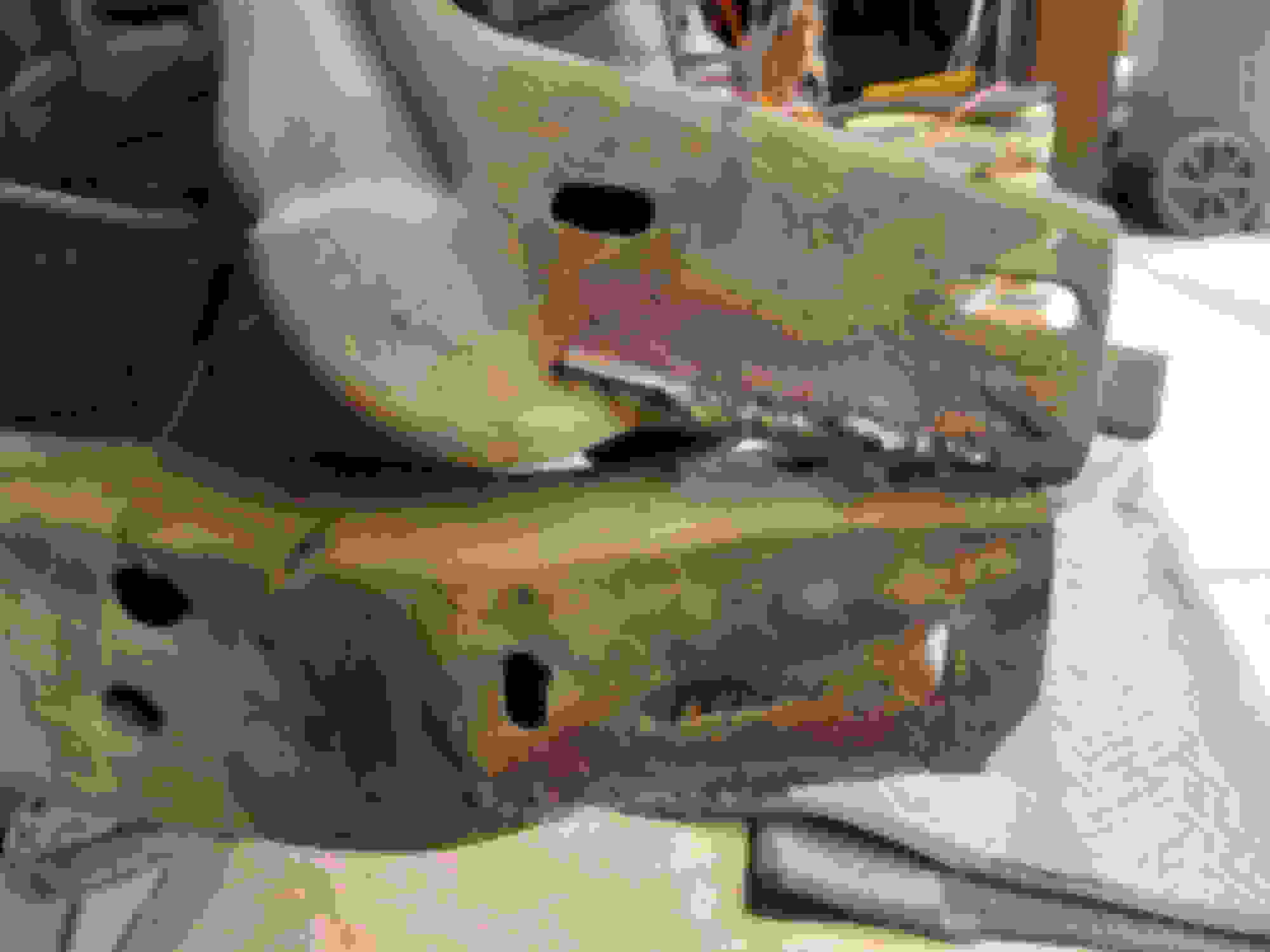
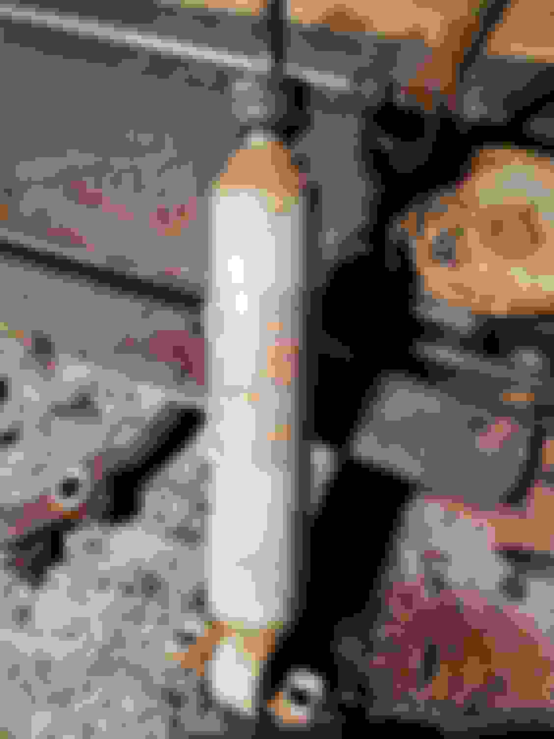
While cleaning the frame I came across a couple concerns and I need some feedback on one. I found a bad weld at the joint near the front body mount that was not complete from the factory. It is cracking a bit at the top and bottom so I will re-weld it. The concern I need feedback on is the control arm mount. The weld that holds it to the frame looks incomplete and possibly weak. Should I complete the weld on it or leave it alone? I know it has been that way for 50 plus years, but the car never had 500 horse power before.
The frame...
I would "stop drill" the crack on each end of the crack to stop it with 1/8-3/16" drill and stich weld it. Take measurements to see if things are moving.
.........Just my two cents worth
I would "stop drill" the crack on each end of the crack to stop it with 1/8-3/16" drill and stich weld it. Take measurements to see if things are moving.
.........Just my two cents worth
That crack/opening is where two pieces of the frame are connected. I was thinking of grinding the crack out and welding it back together. A little more involved than just drilling holes but the same concept.
It looks like someone put a partial frame on it at one time..back then, GM sold partial frames
This had me concerned that you may be right so I did a little research and found a few pictures of other frames at that same point and it looks like this is a factory frame connection. Meaning that weld is supposed to be there. It is NOT supposed to be open like that, but still there. I will see if it is possible to get a punch or some other rod through the frame from the inside and pound it closed a bit more and re-weld it shut. If I can't reach it from the inside, then the BFH from the outside will close the gap before welding. Just have to grind the cracks out first.
This had me concerned that you may be right so I did a little research and found a few pictures of other frames at that same point and it looks like this is a factory frame connection. Meaning that weld is supposed to be there. It is NOT supposed to be open like that, but still there. I will see if it is possible to get a punch or some other rod through the frame from the inside and pound it closed a bit more and re-weld it shut. If I can't reach it from the inside, then the BFH from the outside will close the gap before welding. Just have to grind the cracks out first.
Drill a hole where the crack ends before welding. This will stop futher cracking.
Repairing heavy gauge steel, actually anything thicker than "sheet metal", in my opinion and experience, if you want it to last, and when talking about typical home-conditions, you wont beat quality MMA-welder, if you want it to last.
Especially with "new" inverter technology and aids.
Its just ridiculous how forgiving its in home-conditions. And it makes way better/harder seam than some lousy MAG/MIG typically people own. Also changing sticks is easier than changing wire/ gas.
Just personal opinion with some experience from heavy machinery repairing on field/ on workshop. Plus home metalworks.
We have a different standard for rating rods, but closest thing i found from your standards, is E7018 H4R.
Fantastic general rods. If you want to search closer and see data-sheet to compare for your local rods, google " ESAB OK48.00". Thats what i would use.
Cjsdad..........I would check with a welding supply near you. 7018 may require DC reverse polarity. 6011 and 6013 might work with a conventional "stick" welder.
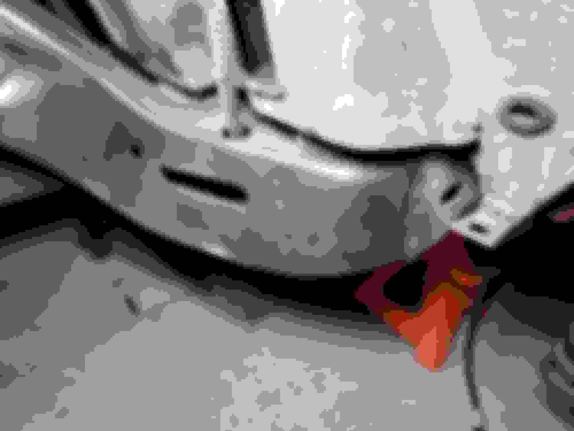
Being a novice MIG welder I have a MillerMatic-190. You set it on automatic and it will control the wire speed and heat all in one. I used 25 gauge wire and got good results in terms of the amount of heat and penetration on the repair. The repair pictured was bad body mount hole. I bought the large washer from Fastenal and grafted it in. Used 30 gauge on the the floor and trunk pans. I practiced with some scrap metal before I started repairs. If I would have decided to send the amount of repair work this car needed, I could have bough 3 complete MillerMatic 190's and know I have learned something I enjoy doing. Just some thoughts...
To floor and trunk etc, i would use MAG also. I bet you MAG'ged it. 99% of times people speak about MIG-welding, they actually MAG-weld..
But back to subject, yes, for "sheet-metal" like floor-pans, id use MAG every time, due to heat. And you CAN repair "anything" with MIG/MAG too. Boils down to preference. My preference is MMA when i need weld to last, and especially when metal gets thicker, pre-cleaning is not possible/ cant do it well, and especially if welding outdoors.
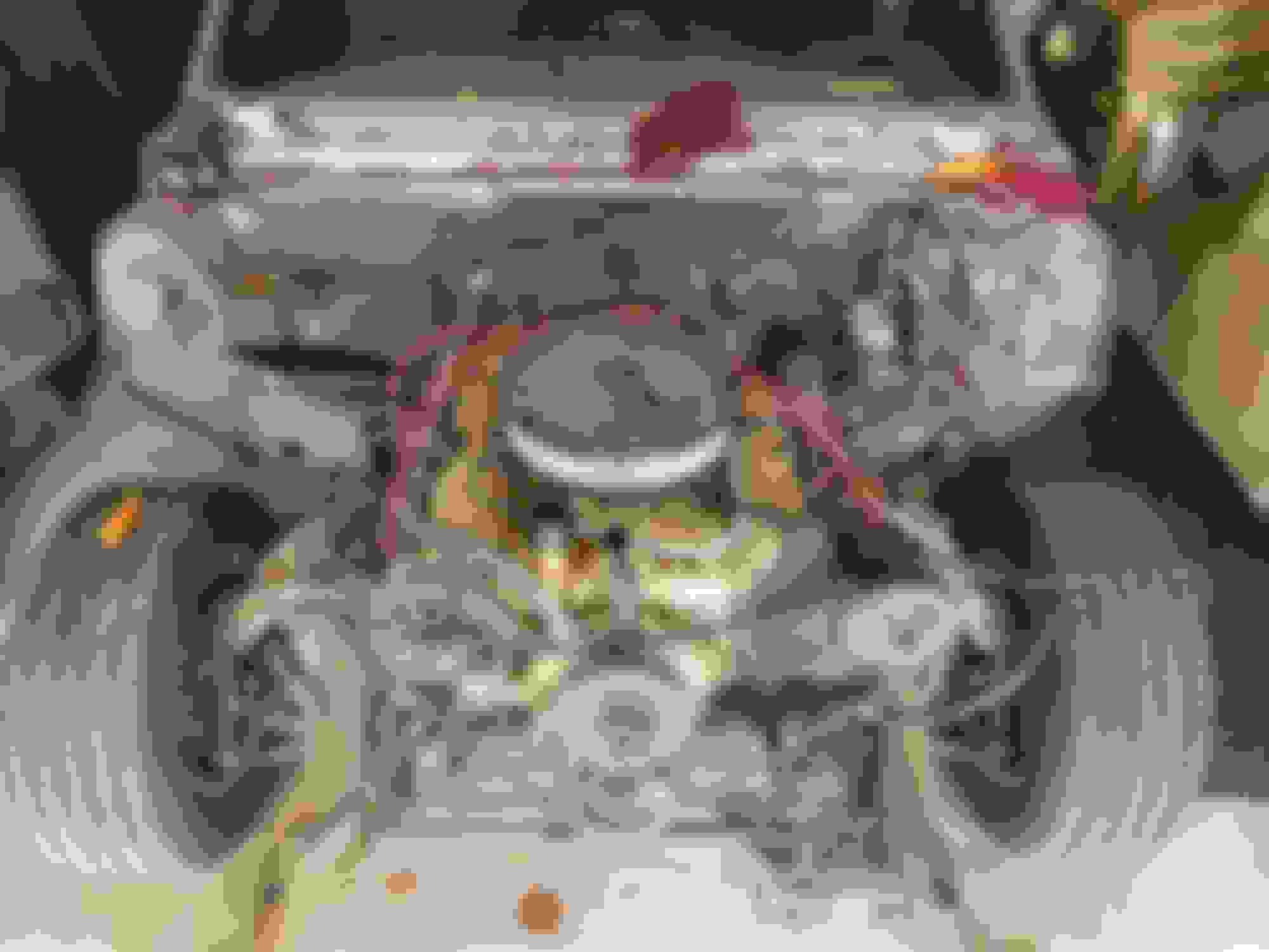
It has been a while since I updated this thread so I thought I would try and catch up. When I left off I was working on cleaning up the front suspension. I was able to complete the driver side but was in such a hurry that I installed the wrong disc. I put the passenger side disc on the driver side so when I get back to the suspension I will need to swap those. I have different threads all over this site so I will try and incorporate them all here. The engine and trans have been installed. They were installed the first time in such a hurry that I skipped a lot of important items. The engine mounts were in bad shape and needed to be replaced so that was done later while the engine/trans were out in order to add extensions to the transmission corssmember mounts. The TV cable was installed. The trans dipstick tube was installed. Headers installed, and removed, and installed again with an O2 sensor. The exhaust has been installed. The under-hood wiring has been installed. Part of the fuel system has been installed. And other little bits and pieces have been added to help get things ready for firing the engine. Now for the pictures...
The engine, not visible in this photo is the TH200-4r behind the engine.
The deep oil pan does hang below the crossmember, but only an inch or so.
Last edited by cjsdad; May 22nd, 2020 at 09:00 PM.
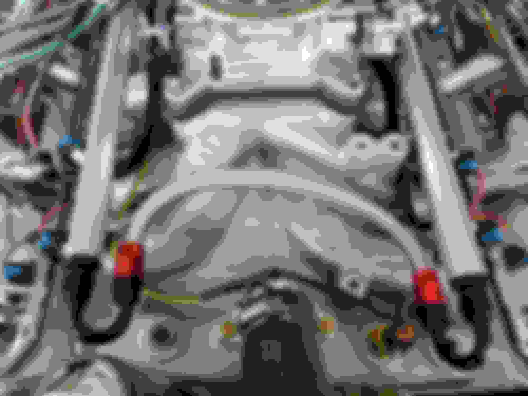
Once the engine and trans were in, I learned that my vehicle left the factory without the transmission crossmember mount extensions, so I had to make some. It took a little trial and error on the fabrication but the install went well and the crossmember is now installed and fits well. Installing the new engine mounts at this time raised the engine enough to give the headers more clearance.
Trans crossmember mounts.
New engine mounts and raised engine. BTW, the fuel line seen in this photo did not have a clamp on it. I found this out after the old engine was out and I wiggled the fuel line. It has of course dried out and become loose since it was installed and that may explain the fuel starvation the old engine was experiencing.
The driver side header needed to be clearance a tad in order to clear the engine mount. This was the only adjustment needed to install the headers on the engine.
Last edited by cjsdad; May 22nd, 2020 at 08:56 PM.
The passenger side header was removed in order to install a bung for the O2 sensor. I started with an angle bracket that happened to have the correct size hole in it. Tapped the hole, and welded the bung to the header. Reinstalled the header and screwed in the sensor.
Installing the under-hood wiring required a larger hole in the firewall so I used a cardboard test to find the correct size hole saw. I then needed to drill another hole for the factory wiring. I lengthened and shortened a lot of the sensor wiring and still need to find a suitable fuel pressure and oil pressure sensor to complete the wiring. It is still a bit of a mess on the firewall so I will do a lot more cleaning up on the wiring before I am done.
I have fabbed a mount for the TV cable and added a couple buttons to the throttle bellcrank. It turned out pretty nice. Not sure yet if I want to completely strip it and leave it "in-the-white" or paint it a different color. Maybe a nice aluminum color to match the surrounding area. I may also move a few washers around on the throttle linkage to straighten out the link rod. Pictures show a lot of things you don't look at while setting things up.
Last edited by cjsdad; May 22nd, 2020 at 10:06 PM.
I have installed some of the fuel lines but that is where I am at now. Need to run the fuel line to the tank and install the fuel pump and filter. You can see the regulator and the fuel lines going to the firewall in the first pic. The gauge is not fully intalled, that is why it is up-side-down.
Last edited by cjsdad; May 22nd, 2020 at 10:04 PM.
The exhaust is installed but I don't have pics of that yet. I just finished it the other night. So this post will serve as a place holder for those.
As promised, pics of the exhaust. This is the first time I have looked at it through the camera and like I said above, the camera sees things you don't ordinarily see. For instance, in the first pic everything looks fairly nice, right.
But on closer inspection, things are a bit off and will need some fine tuning.
Things are a bit off-center and lopsided. It should be easy to fix, somebody hold my beer...
Having all the parts of the exhaust kit marked driver and passenger side helped quite a bit when it came time to actually put it under the car. The sections that go over the rear axle are particularly non-intuitive. They turn inward, not outward like you would think.
The tips are a little too low under the bumper so that will need some adjustments as well. I may cut them a bit shorter and put turn-down tips on them. Tuck them up completely out of sight.
Ok, that was all the good stuff. Now for some of the ugly. Because of the headers being made for a big block, they hang down a little bit. They were pointed down slightly so I used the floor jack and a couple 2X4s to push up on the collectors. It did work, they are now parallel to the underside of the chassis but still too low and too short. The first turn in the pipe would not clear the crossmember So I made a cut in the first extension pipe, angled it up, and added six inches. It's not pretty, but it now fits the crossmember and hugs the bottom of the car.
So, all in all, it looks like a decent system and fits more or less. I expect it would fit better when using the the front mount for the trans crossmember location. I can't wait to hear it!
Oh yeah, somebody in the past history of the car cut out the middle floorboard support. I'll need to fix that...
Last edited by cjsdad; May 23rd, 2020 at 09:00 PM.
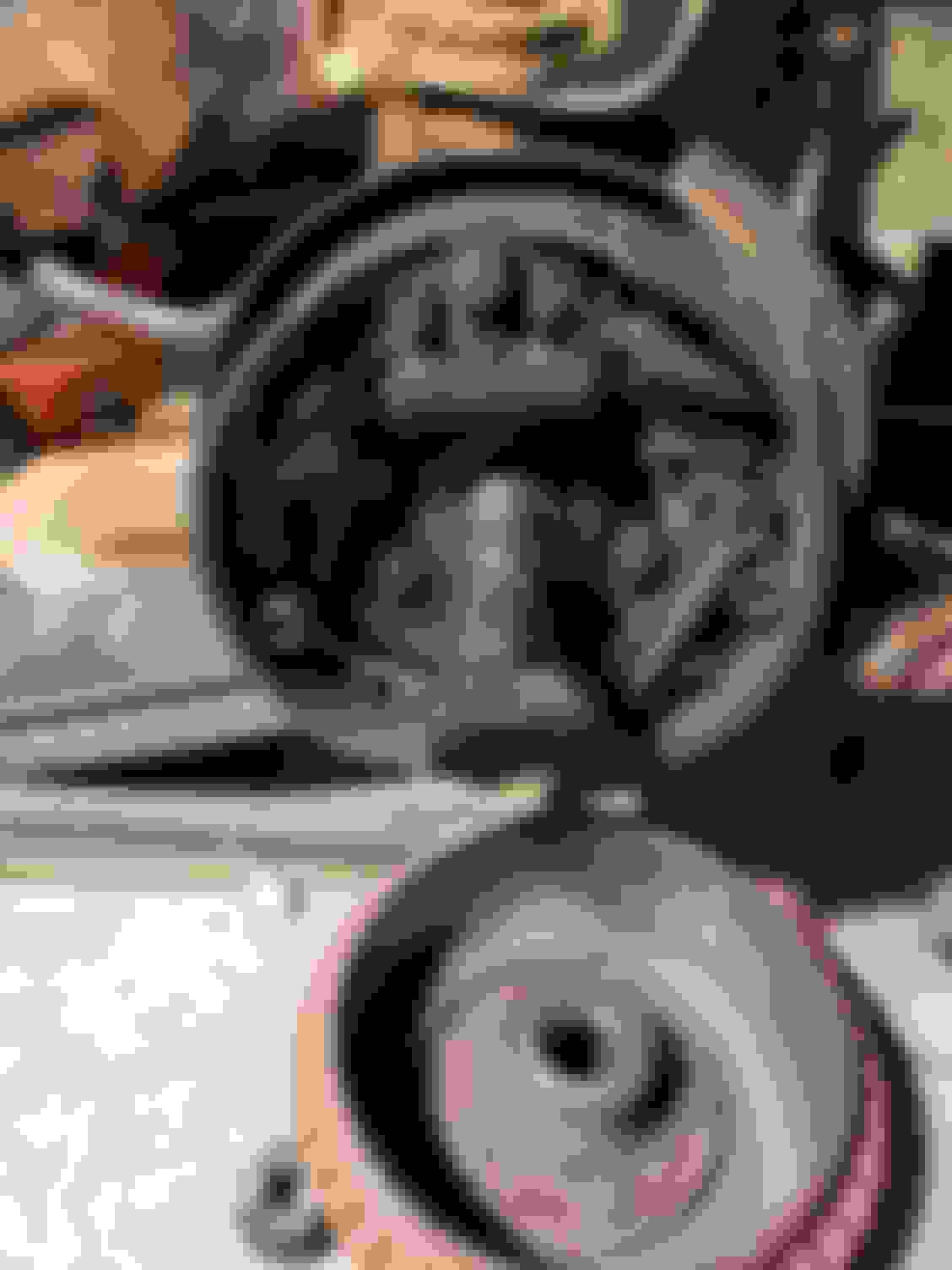
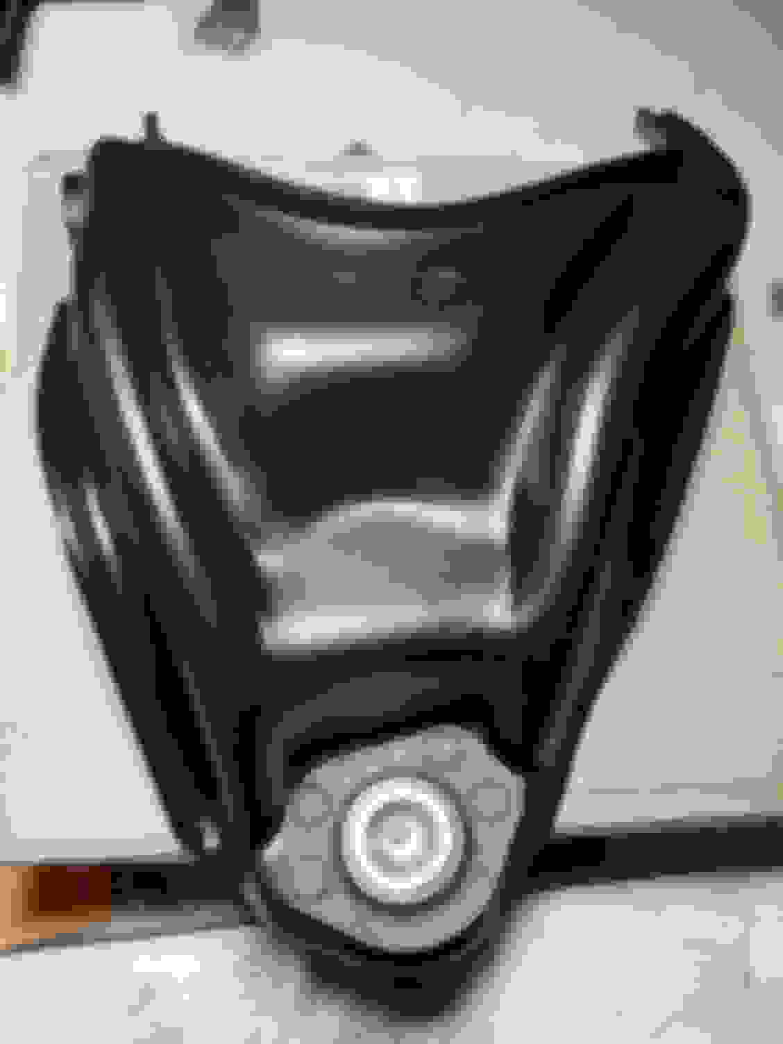
I cleaned up the crank and water pump pulleys. The crank pulley had been cranked down onto the harmonic balancer of the 330 engine in such a way that it bent the inside rim and needed to be flattened and then filed out round again before it would fit on the new balancer. I'm still deciding if I want to replace the water pump with a shorter one or get a longer pulley.
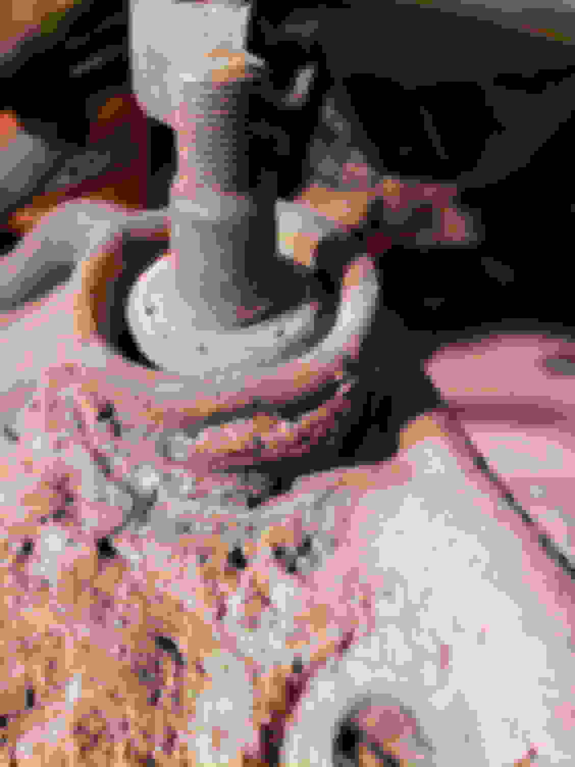
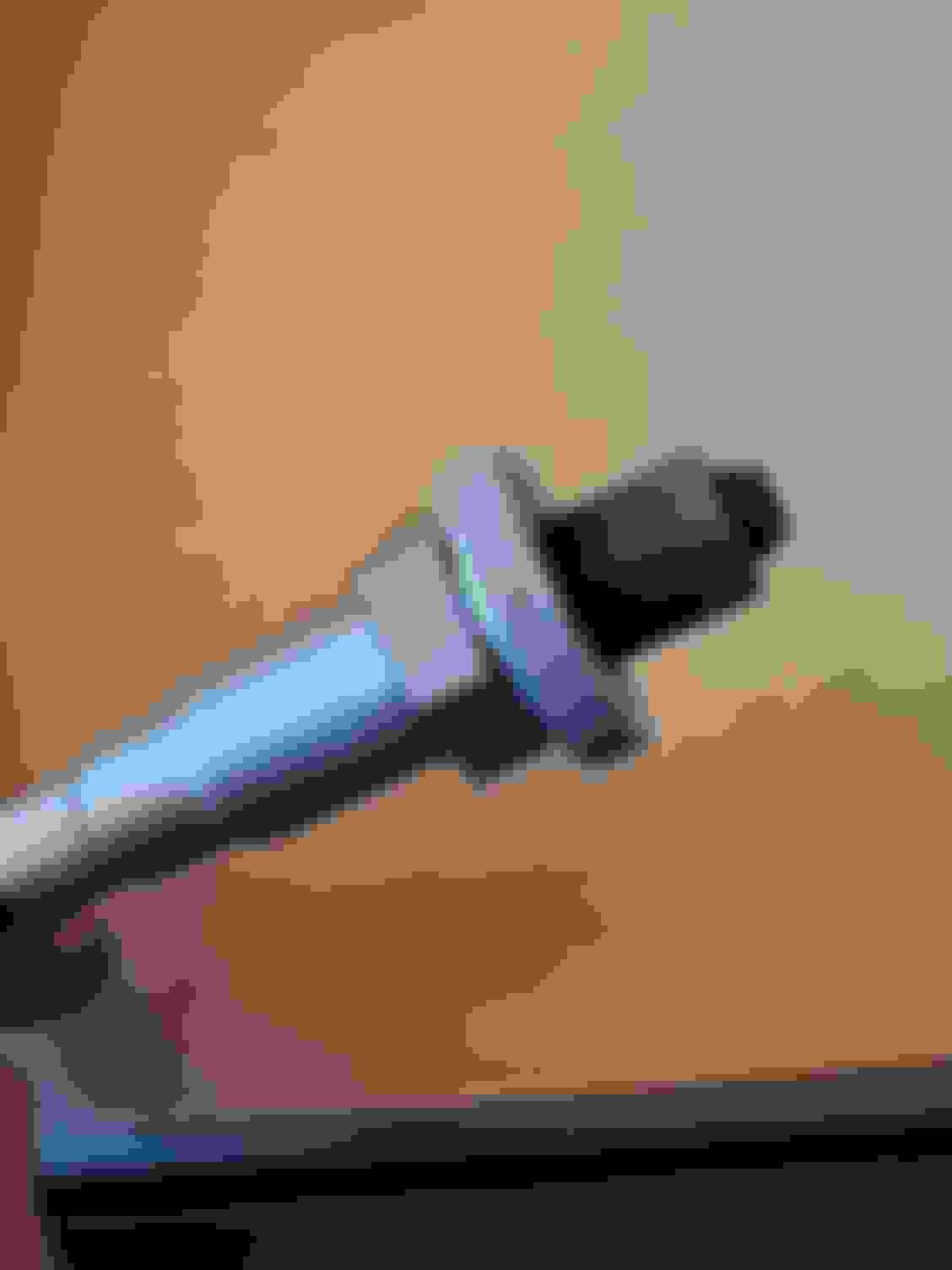
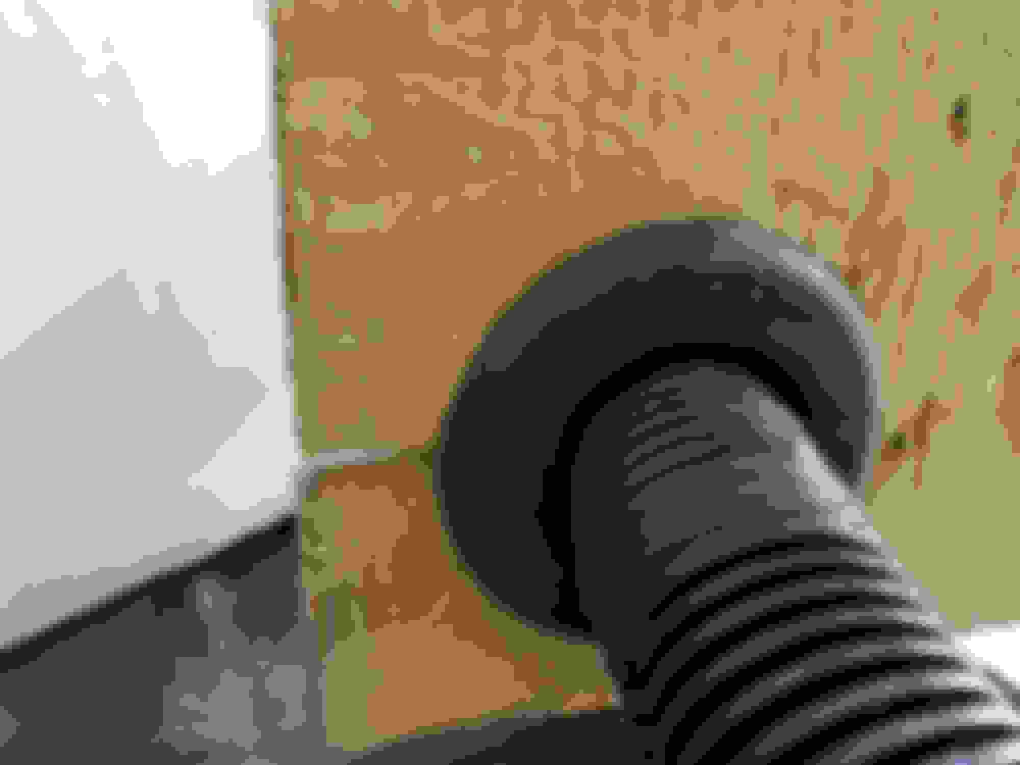
So, I think I figured out why my old transmission was leaking, I was cleaning the slip-yoke the other day and found some issues. As you can see in the pics below, there are nicks and gouges on the outer surface and they are at 90� to each other. Makes me wonder what the inside of the output bushing looks like in the old tailshaft housing. Makes me wonder what happened to this yoke in the past too. Gonna have to get another one.
I was able to get the starter installed last night but it was a fight. The electrical contacts are on the side of the new mini-starter so I had to clearance the header tube. It required taking the header out, dent-tuning it, partially installing the header, installing the starter to check for clearance, and doing it all over again until it fit. Because the original battery connector had a 90� bend in it, I cut it off and installed a straight connector and wrapped it with three layers of shrink tubing. I also shortened the solenoid wire so that it would be roughly the same length as the battery cable. I ended up with about 1/8th inch of clearance but that is enough. I may eventually use some ceramic wrap on the headers and that will also give a little extra electrical insulation. I was able to make a new mounting bracket for the original insulator tube from a different vehicle that will keep the starter wires away from the heat of the headers. After all that, I was dog-tired! Getting closer...
looks like some one at some time in its life had the yoke in a vise changing joints perhaps. just a thought here about the throttle linkage,why not do what I did to clean it up, used the floating pedal and cable from a 73 74 nova,direct bolt in,just a little square hole in the firewall.
looks like some one at some time in its life had the yoke in a vise changing joints perhaps. just a thought here about the throttle linkage,why not do what I did to clean it up, used the floating pedal and cable from a 73 74 nova,direct bolt in,just a little square hole in the firewall.
Dunno for sure what caused the damage to the yoke, the u-joints were still factory with the injected plastic holding it in. An unsolved mystery. As for the throttle, that would work quite nicely and I have considered using that type of set up but I don't have time to go to the wrecking yards to find one. Eventually I will find something like that but for now I have the factory set up and it works. It is a bit crowded on the firewall but it still works.
Installed the water pump from the old engine to line up the pulleys just to get things moving along. I will probably replace it some time soon, but for now I know it works.
So I went to the wrecking yard to pick up a drive line. Nothing available in the length I need so I settled for just the yoke and while I was there I also picked up a newer throttle pedal and cable. The throttle pedal and cable were not too much of a fight. I will still need to get it properly supported, the floorboard is a bit uneven where it is attached. As for the drive line yoke, the one I picked up was out of a newer truck and was a bit too long for my needs. A little attention from the band saw and a grinder or two and it's all installed and ready for work.
Last edited by cjsdad; June 29th, 2020 at 08:31 PM.
Getting some work done on the fuel system also. I used braided line for the primary fuel line to feed the injector rails, the regulator in-line after the rails and used the factory 1/4 inch line for the return. The fuel pump and filter are mounted to the bottom side of the trunk floor. I used two long bolts mounted to an aluminum plate with nylock nuts to hold the filter on, then put grommets in the mounting feet of the pump to help reduce noise transmission through the floor. This puts the fuel pump even with the bottom of the fuel tank. I will put a heat shield between the fuel system and the exhaust when everything is completed and running. The tank looks a bit rough from the outside but it is clean as a new penny on the inside. I need one more connection to complete the fuel system.
I finally got the engine running. It was a total cluster bomb to do it, but with Mark's help and patience, it lives! The AEM Infinity ECM is designed as a stand-alone system but needs an ignition module to get the spark going. The trouble is, the AEM will not trigger an MSD or even a new digital Summit ignition system. It needs an Ignition Control Module to amplify the 5V output of the AEM to a 12V signal that will then trigger the MSD or Summit ignition. But it finally works! I'll see if I can post a video later, but was so excited to tell everyone, I had to post about it tonight.
Getting a few more things done before I can drive the Hooptie. I was having trouble with the engine running on after turning the key off because of the charging system back-feeding and keeping the ignition system energized so I pulled the trigger on an alternator upgrade. 100 amp output to keep up with any modern electronics I may add in the future. A kick-*** stereo for certain.
The power steering pump was just too intrusive and ugly, it was hiding my new engine. The factory rear bracket would not fit due to the fuel rails anyway. So I managed to make a smaller profile pump fit on the engine. A little cutting, a little welding, and a little grinding and it looks really nice down there. I need to re-seal the steering box and install the hoses and I can actually drive the car again.
 December 2nd, 2018, 11:43 AM