When you click on links to various merchants on this site and make a purchase, this can result in this site earning a commission. Affiliate programs and affiliations include, but are not limited to, the eBay Partner Network.
Hello all! Glad to be a new member here and the olds fourms! I’m the proud owner of a 67 delta 88 4 door holiday hardtop with the 425 engine. Looking for a full engine vacuum/heater vacuum diagram as the person that owned the car before me really messed up the lines. I’ve got some unhooked and don’t have a clue where they go. Most lines are original but will be replaced when I figure all lines out. And advice and pics would be great!!
Very nice car. I have the convertible version of the same thing. It's even the same color.
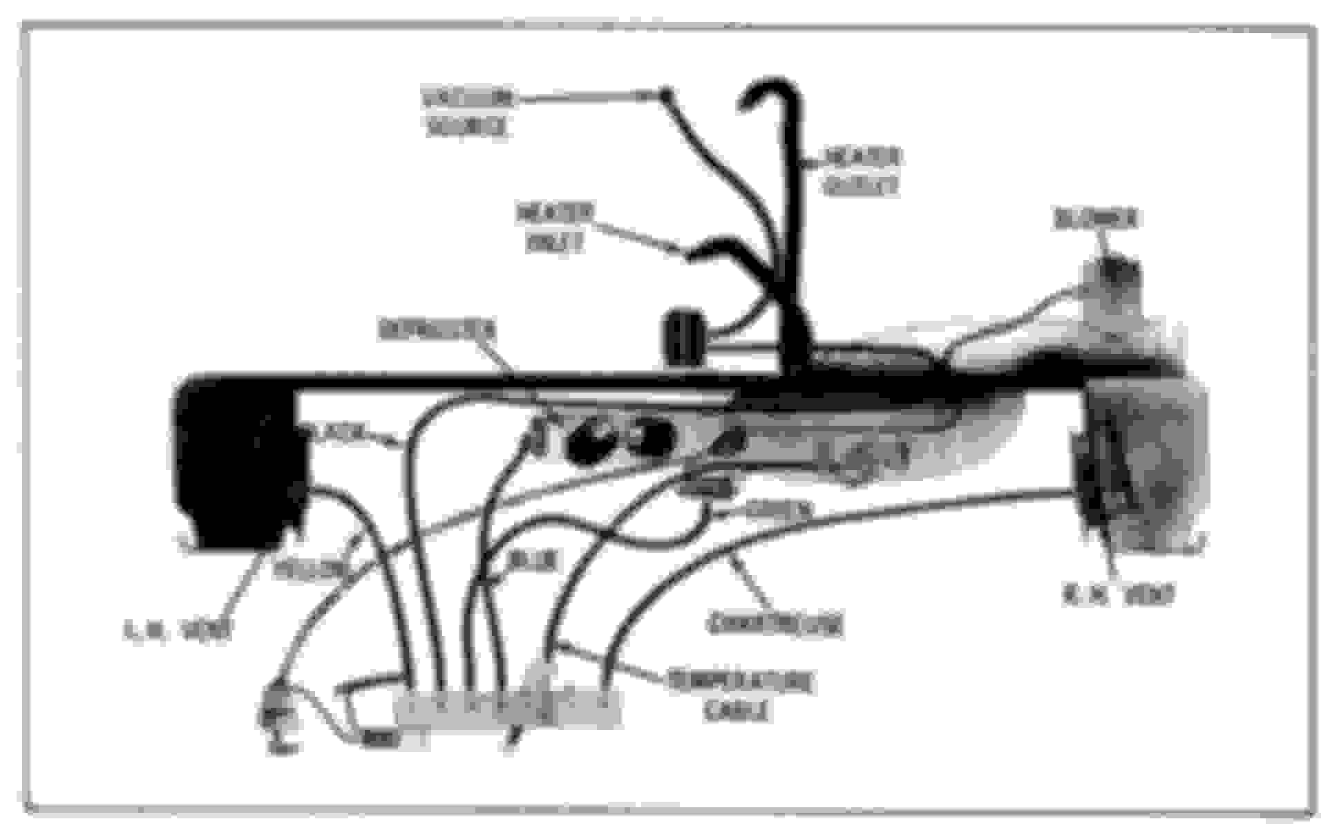
You did not say for sure if your car has A/C, but you didn't mention it, so I assume it doesn't. If it does not have A/C, the vacuum hose system for heater control could not be simpler. The diagram is below. It comes from the '67 Olds Chassis Service Manual, and if you don't have one of these, you should get one. They're for sale on ebay regularly.
Starting under the hood, there is a vacuum line from a port on the intake manifold ("vacuum source" on the diagram) to the black vacuum reservoir mounted on the firewall (not labeled). From there, a black hose goes through the firewall and connects to the control head on the dash. From that control head are several vacuum lines going to the left and right hand vents ("yellow" and "chartreuse"), the defroster control ("blue"), and the air inlet door ("green"). That's it. These lines are not fully yellow, blue, etc. but rather are black with a stripe of the noted color. All of this is true if the lines are original. If they've been replaced, they're probably all black.
I recently went through these lines on my car because I could not get air to come out of the defroste nor the left and right hand vents. It turned out that the blue hose had been completely disconnected, and the vent hoses were dried out and stiff where they connect to the actuators. I simply snipped the ends down to softer rubber and reattached them. If the hoses are original, they're 51 years old, and rubber can stiffen over that much time, especially when it's stretched, such as it will be when it's slipped over the end of a fitting.
The thicker lines labeled "HEATER OUTLET" and "HEATER INLET" are the coolant lines going to the heater core.
Thanks for the reply!! I forgot to even mention about the ac lol. Yes my car does have ac and one cable. On my car for some reason has 3 lines coming out of the firewall and all are getting vacuum supplied from the intake. It’s very confusing to me the way it is and makes no sense. Also the car does have a vacuum operated trunk latch. As for the manual, I did purchase all the the manuals for this car on a cd for $39! I saw this one but my car doesn’t have the vents on each side and that’s probably because it’s got ac lol.
Having complete information helps. Any diagrams you need are in the manual you bought. The vacuum hose diagram for the A/C system is in Figure 1B-100 on page 1B-52 in the chassis manual.
The CD versions of these manuals are just scans of the original paper manuals. There can be drawbacks, the most significant of which is anything that was originally in color, such as the wiring diagrams. If those were scanned in black and white, then all the value of the wiring diagrams is gone because it's impossible to trace wires. In the end, you might find it better to have an original, paper manual.
I overlooked that picture last nite while scanning for a pic of the unit I have. The only thing that confuses me is there are two lines that seem to go to the fan motor. I have 2 vacuum canisters in this car and they are both under the fan motor so maybe they go there I’m not sure. I also seem to have 2 vacuum ports on the intake. One goes to the transmission and that’s also tee’d off and goes to the heater control. The one in the rear goes to both vacuum canisters. This doesn’t seem right. Is there a diagram of the engine vacuum lines? And thanks for all of your help!
I overlooked that picture last nite while scanning for a pic of the unit I have. The only thing that confuses me is there are two lines that seem to go to the fan motor.
Did you look at Figure 1B-100? It shows two vacuum lines to the blower assembly. One of them goes to port 6 on the round A/C control in the diagram, and the other goes to port 3.
Originally Posted by Cooldude48818
I have 2 vacuum canisters in this car and they are both under the fan motor so maybe they go there I’m not sure.
That doesn't appear to be correct. The diagram shows only one canister. Are they connected to anything? Possibly connected in series? Maybe some former owner thought that having two would be better than one.
Originally Posted by Cooldude48818
I also seem to have 2 vacuum ports on the intake. One goes to the transmission and that’s also tee’d off and goes to the heater control. The one in the rear goes to both vacuum canisters. This doesn’t seem right. Is there a diagram of the engine vacuum lines?
There's no problem here. There are several things that connect to engine vacuum. The transmission modulator is one. The PCV valve is another. Power brakes require vacuum as well. You just want a good vacuum line from an engine manifold vacuum port to the vacuum canister. If it comes off a tee, fine, as long as a connections are tight. That is the only vacuum connection between the engine and the Heat/A-C system. I'm curious about the vacuum line going to both vacuum canisters. Is there one vacuum line to each canister? Or one single line to one canister, and then that canister is connected to the other canister?
There is no one single engine vacuum hose diagram that I have ever found. The manual shows the different vacuum connections depending on the system involved. The heater system vacuum lines are in the figure I mentioned above. The PCV vacuum connection is shown in Figure 6L-4. The transmission vacuum modulator connection is shown in Figure 7-26. The power brake vacuum connection is shown in Figure 5-42. Get out that CD you bought and start looking through it!
One other suggestion is that, if you don't already have one, you might want to get yourself an engine vacuum gauge. They are an invaluable tool in diagnosing engine issues. I'm wondering if the reason there are two vacuum canisters on your car is because a prior owner found the heater/AC control to not work well, thought it might be due to low vacuum, and thought that adding a second canister would help. Get a gauge, connect it to a manifold vacuum port (cut a hose and put in a tee if you need to, you can cap the tee when the gauge is not connected), and see what the gauge says when the engine is running and warmed up. If the vacuum is lower than it should be, you have a vacuum leak somewhere, and that could cause problems with the ventilation system. One thing that I'd suspect is the vacuum hoses to your two vacuum canisters. Something is not correct there.
Last edited by jaunty75; October 31st, 2018 at 07:13 AM.
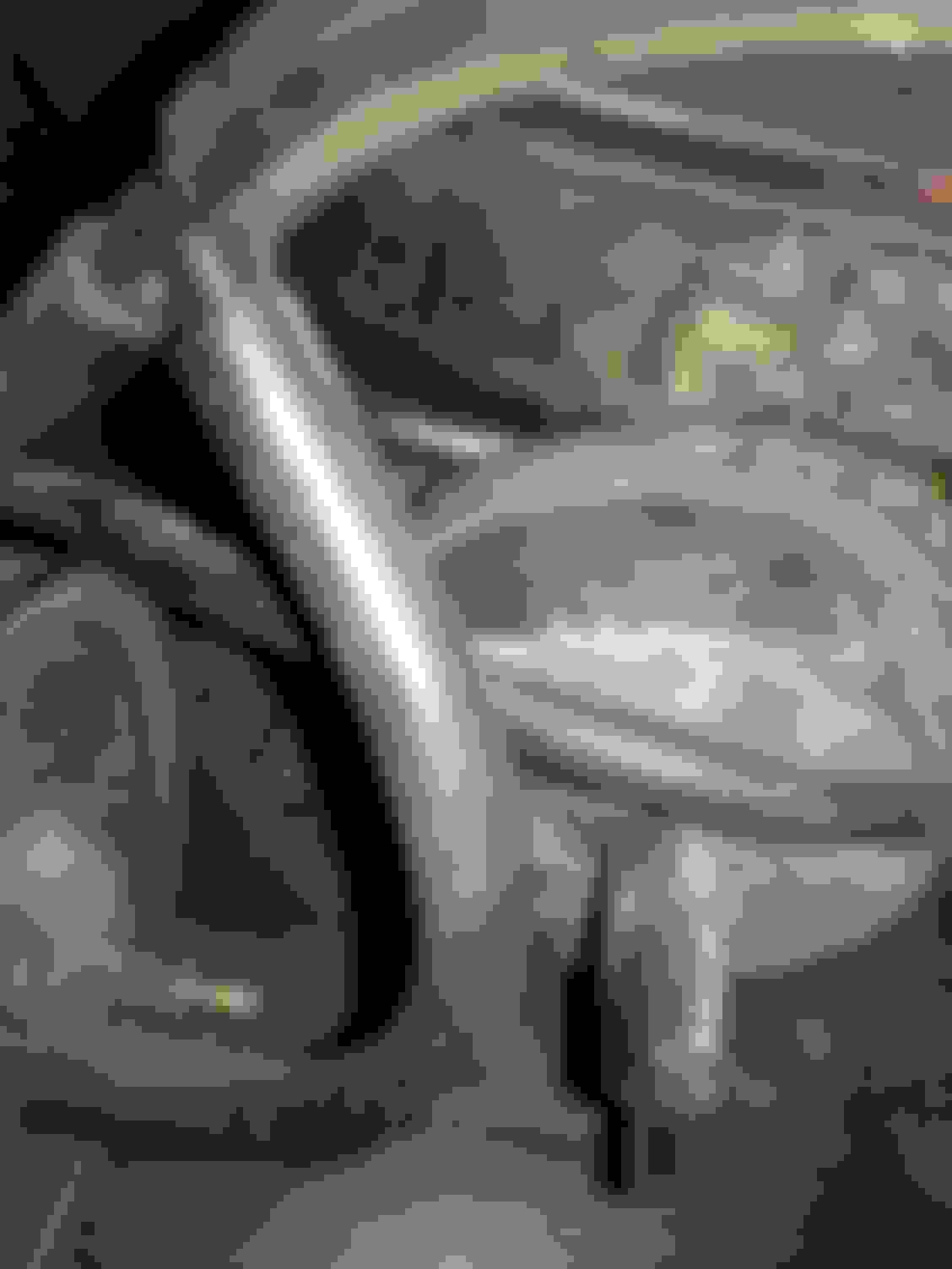
Ok. Here is what I’ve got. The two vacuum canisters are hooked in series. The silver looking thing is a valve under the heater blower motor. It does have 2 connection points. Have not checked engine vacuum but do have a gauge. I’ll report back tomorrow. Pics below. This is under the blower motor mounting in engine compartment.
The two-canister arrangement certainly does not look factory, and every vacuum hose I see in your photos looks old and cracked. I notice also that there's a white tubing joiner in the upper right of the first photo, which is also not factory. I'd remove one of the canisters, find the vacuum line that goes through the firewall and connect that to one port on the remaining canister. The other port on the canister connects to a vacuum port on the engine. I'd replace every vacuum line you can find.
That valve-looking thing under the heater blower motor is supposed to be there according to the figure in the manual. There are two vacuum connections to the blower assembly, and I think one of them goes to that valve, which is actually a vacuum actuator.
Like I said, going to replace all the lines just wanted to make sure where they were all going before I did it. Didn't want to wast money on extra vacuum lines. Your awesome and thanks so much for all your time and effort in helping me figure this out!! I’ll do like you said and remove the one canister and see what everything does after that.
Mess also thinking of going hei to get rid of the points system. What are you thoughts on that?
Mess also thinking of going hei to get rid of the points system. What are you thoughts on that?
I changed mine to electronic ignition (not HEI) in 2014. Changing to HEI is more complicated as it was never offered on this car and requires a new distributor, new type of plug wires (I think), and perhaps different spark plugs.
I think what you mean is to change it to electronic ignition to get rid of the mechanical points, as you say. MUCH easier and cheaper, and it works well. You use the original distributor, just change the innards. I've been running my car for four years with it now, and I haven't had to do anything as far as tune-ups since except change spark plugs. I also put in new plug wires and a new ignition coil at the same time. The instructions that come with the kit guide you through the process.
Oh lord she's handsome... those mid-60s Holiday Sedans are just gorgeous. Glad you were able to get the HVAC going. Was going to ask if it is a Comfortron car or Custom A/C as vacuum connections are way different. Comfortron has one lever and a temperature dial. Custom A/C has a lever and a set of pushbutton controls.
I think mine is the custom as it has the cool to warm lever and then push buttons for floor and vent and defrost. I believe I ya e it hooked up correctly as the air goes where I tell it to go lol.
 October 30th, 2018, 03:00 PM