When you click on links to various merchants on this site and make a purchase, this can result in this site earning a commission. Affiliate programs and affiliations include, but are not limited to, the eBay Partner Network.
Thanks Joe. I'm definitely one of those people since there are a lot of firsts for me with this engine and me being used to only inline 6s.
I'm not interested in reducing NOX or heating my engine up more than it has to. The way I think I understand you is that the system basically is bypassed in the higher gears and the engine would run just the same as it would if it wasn't there at all. At lower speeds/ temperatures/ gears it changes the timing to reduce Nox at the expense of driveability. I'm not sure where the fuel economy gains come in? If there is no real benefit for me nowadays and there is no other gain from the DVCS / TCS at cruise speed, I'd be inclined to hook it all up, but unplug the temperature wire as you said. What about your point of it going to ported, but not manifold vacuum? Do I need to worry about that?
There are two separate issues at work here, the choice of ported vs. manifold vacuum to control the vacuum advance, and the TCS. Let me start with the TCS. The system is simply a solenoid valve that either opens or closes the hose that provides vacuum advance to the distributor. The solenoid valve is incorporated into the DVCS for the 1971-72 model years, but that is only to reduce cost. In 1970 it was a separate part. There are two wires going to this valve, one is key-on power and the other is switched ground. A pressure switch (for automatics) or mechanical switch (for manual trans) is closed when the trans is in any forward gear other than high gear. When this switch closes, it completes the circuit to ground, energizing the solenoid valve, which causes the valve to turn off any vacuum to the distributor. Disconnecting the wire (or removing power to the circuit) disables the solenoid valve, so it is open all the time and the distributor sees vacuum.
The other issue is how the vacuum advance is operated. There's a bunch of theory in this, and ported vs. manifold discussions rival religion or politics for fanatics. In general, more advance (up until pinging occurs) at idle and low speeds will lower engine temps and improve part throttle economy and driveabiltiy. Conversely, less timing at startup can make staring easier. The engine doesn't care if this advance comes from initial timing, vacuum advance, mechanical advance, or an ECU, all it cares about is when the spark is fired relative to TDC. The "best" source for vacuum advance depends on your particular engine, and specifically any decision needs to take into account initial timing, mechanical advance, and total timing, in addition to any engine mods and the fact that 1960s engines were never designed to run on the cat urine that passes for gasoline today. If your car is relatively stock, I'd start with the factory connections (ie, ported vacuum) and factory timing specs. Disable the TCS by pulling the plug and see how it runs. Now try the same thing with the distributor connected directly to manifold vacuum. You may find that in either (or both) case, you will need to reset the initial timing due to pinging. The problem with dialing back initial is that it also dials back total timing, which will be a problem. To be honest, unless you want to delve into a science fair project of tuning your advance curve, I'd pretty much stick with the stock setup.
One more thing. Olds went to ported vacuum as the distributor source in the mid-60s, before TCS. In most cases, Olds included a "safety" in the form of a thermal vacuum switch to switch from ported to manifold vacuum if the engine started to overheat. That is the other function in the DVCS on your car, so keep that function if you use ported vacuum.
Location: Edmonton, AB. And "I am Can 'eh' jun - eh"
Posts: 24,525
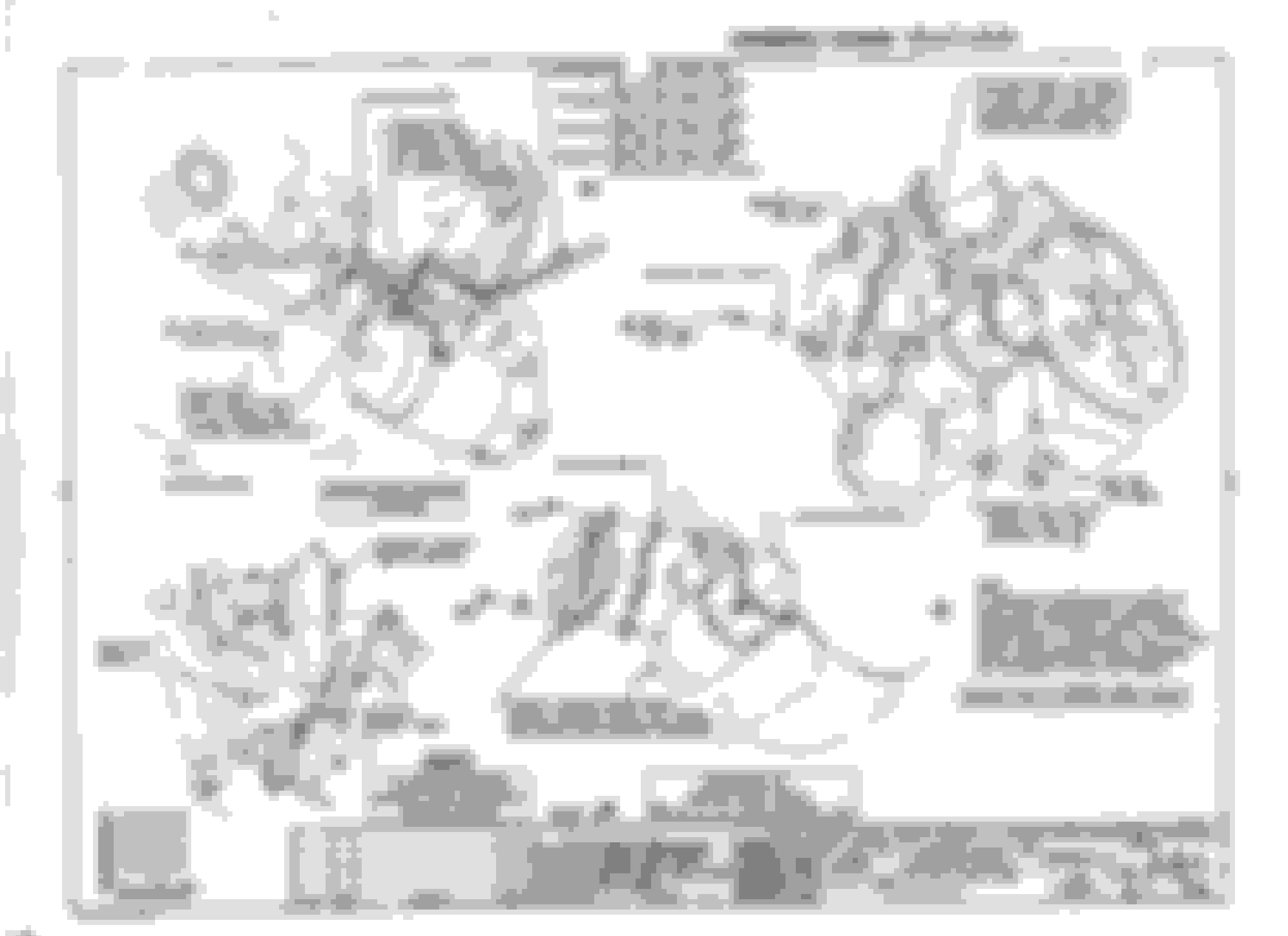
Back to the original question, here's the page from the 72 Cutlass Assembly manual (Engine Dress section) that shows the wiring routing you were asking about. I didn't remember it was hidden away in that section. It clearly shows the phenolic tube location for SMT (manual trans) and AMT (Auto Trans). The brace is shown as is a heat shield which is for N10 (dual exhaust 350 cars) My car was converted to dual exhaust and it doesn't have clearance issues or a heat shield. Note: if your car didn't have shims between the starter and block, disregard the information that shows shims.
Perfect timing Allen. I just got out from under the car to see if I could find a sketch that shows what is all part of the wires coming from the junction box. The pos. battery cable is separate. I have the purple and the thin yellow/ black wires in a harness coming from above from the firewall and the red wire from the junction box seems to be separate too. Does that sound right?
Also, my car was converted to dual exhaust too, so does that mean I should have the larger shield too instead of just the single strap? Do I see that correctly? That would make sense.
Last edited by tcolt; February 5th, 2019 at 02:32 PM.
FWIW, the wires you described are the same as mine - purple, yellow black and red from the junction. It's gorgeous outdoors and I just had a belly full of cappuccino - I'll take some pictures for you. After having spent significant time with a magnifying lens reading the color-coded wiring diagram (I had two separate lighting shorts I needed to troubleshoot [successfully]), the wires you described are the same as the OE wiring - woo hoo - that's good news. I have dual exhaust. RH side cross-over is plugged (welded shut) and opened to a RH straight exhaust to muffler and tailpipe off the RH exhaust manifold. I didn't perform this modification - I have a dual Flowmaster exhaust. I don't have the larger shield - I have the single strap.
Glad you get a little time to relax and still help out a poor soul ;-)
Unfortunately, mine are completely burned along a 6 inch stretch. I think I can completely fabricate a new red wire to the junction box, but the yellow/ black will have to be spliced and yellow will have to do from my assortment of OEM Mercedes wiring from the 70s :-)... The main question now is how do I package them together coming from the firewall. Mine may have already been re-taped at some point so I wouldn't mind getting it right while it's all apart...
Last edited by tcolt; February 5th, 2019 at 03:30 PM.
Back to the original question, here's the page from the 72 Cutlass Assembly manual (Engine Dress section) that shows the wiring routing you were asking about. I didn't remember it was hidden away in that section. It clearly shows the phenolic tube location for SMT (manual trans) and AMT (Auto Trans). The brace is shown as is a heat shield which is for N10 (dual exhaust 350 cars) My car was converted to dual exhaust and it doesn't have clearance issues or a heat shield. Note: if your car didn't have shims between the starter and block, disregard the information that shows shims.
Before I answer Norm's posts... I worked on my wiring harness today and I realized that the main problem I had was that the wires were running alongside the solenoid, much to close to the manifold, instead of tucked in over the top. I'm also still trying to figure out Allan's picture in my post number 41, which shows the battery cable together with another cable on the same terminal. What wire is that and where does it go?
Then, on my car, the red wire that goes from the solenoid to the junction box the red wire had an eyelet terminal lug on either end of the wire (not necessarily original, but my guess is that it is). And is it just a separate wire that runs up to the firewall or is it inside some sort of sleeve? It looks from the top, left sketch above that the yellow/ black and the purple wire run inside some kind of odd-looking sleeve or is that supposed to symbolize tape wrapped (along with the two wires that go to the transmission)?
Also, on the top right hand sketch the bolt that goes through the lower hole of the starter brace there is also a second smaller, horizontal brace that I've seen somewhere else before too. What does that one do and do others have it on their engines too?
Bad drawing. Your analysis is correct - just the width of the cable.
Here is a full page scan from my 72 Cutlass Assembly Manual. Maybe it will help you with your routing and battery tube issue? If I scanned it right, you should be able to enlarge it as needed for better detail.
Patton, in post # 9 you thought that the valve cover tabs weren't used on a 350 AT car as I did too. Joe says they were and that makes sense since I have a harness just loosely running along the valve cover there, over to the alternator. Yet, the sketch above says those tabs were only used on SMT cars?... (I don't know what the S stands for in SMT....) What do you guys think about that? I'm putting together my list of things I have to get from Inline Tube and just wanted to be sure I get the right things.
In post # 10 you said: "The wires to the solenoid, of course, were wrapped in wiring harness wrap material..thin stuff." Can you or others say more about which of the solenoid wires ran together and what that thin stuff is? In the post above, the sketch shows it as some sort of segmented sleeve, but I don't know what that is supposed to represent.
Can you or others say more about...what that thin stuff is?
Tom, the wiring on cars of our era was wrapped with vinyl film (similar to tape, but without adhesive). I may have an extra spool of that film. If I find it in time, I'll send it along with your other parts. It was tucked under and overwrapped on one end and tied off simply at the other end.
The vinyl is thin enough to stretch, so the wrapping keeps the wiring bundle compact. It serves the same function as the corrugated tube used on later cars.
Patton, in post # 9 you thought that the valve cover tabs weren't used on a 350 AT car as I did too. Joe says they were and that makes sense since I have a harness just loosely running along the valve cover there, over to the alternator. Yet, the sketch above says those tabs were only used on SMT cars?... (I don't know what the S stands for in SMT....) What do you guys think about that? I'm putting together my list of things I have to get from Inline Tube and just wanted to be sure I get the right things.
In post # 10 you said: "The wires to the solenoid, of course, were wrapped in wiring harness wrap material..thin stuff." Can you or others say more about which of the solenoid wires ran together and what that thin stuff is? In the post above, the sketch shows it as some sort of segmented sleeve, but I don't know what that is supposed to represent.
If your car is a factory AC car then the wires to the alternator run from the D side wheelwell OVER TO the front of the motor.....they don't run along the valve cover (for example like the Pos battery cable does on a manual trans car). The alternator and gauge/sending unit wires go straight over to the alternator (according to my 1970 PIM - Section 12, Page 166) FORWARD of the front of the D side valve cover. So....tell me why a clip would be needed? It's not used according to the '70 manual.
On the P side valve cover the manual shows the metal tab being used under the center/inboard valve cover bolt to help hold the TCS switch wires and some other items.
Maybe I'm reading the manual incorrectly or your year differs.....don't know.
Location: Edmonton, AB. And "I am Can 'eh' jun - eh"
Posts: 24,525
Patton, you're referencing 1970 and the OP has a 1972. I don't have a 1970 CSM I have a 1972 CSM. I don't know whether the information is the same. Also not sure if the AM is the same for both years. There may be subtle differences.
I believe the wire the OP is referencing (partly in the same loom as the battery cable) goes to the junction block.
Location: Edmonton, AB. And "I am Can 'eh' jun - eh"
Posts: 24,525
Originally Posted by Allan R
I believe the wire the OP is referencing (partly in the same loom as the battery cable) goes to the junction block.
Originally Posted by Vintage Chief
I believe your 1972 vehicle has the horn relay junction block mounted on the firewall (look at the images Allan provided). Therefore, I believe the change between 1971>1972 was the relocation of the horn relay junction box. What appears to me they've done is simple. The tied the horn relay junction block wire (red) into the battery positive lead wire (red) AT THE POINT OF ATTACHMENT where they are both crimped into the terminal at the solenoid. Then, it becomes a short distance to route this horn relay junction block wire (red) directly up the firewall to the horn relay junction block (below).
Location: Edmonton, AB. And "I am Can 'eh' jun - eh"
Posts: 24,525
Originally Posted by Vintage Chief
Standard not Synchronized. Another point for Norm.
Ok, how about we go half way between synchronized to Synchro mesh (which is basically the same thing) Even the Parts Manual simply refers to the Automatic Transmission as AT. Why the Assembly Manuals show AMT and SMT just causes confusion.
For 1970 Rallye 350. Not the same as 1972. More like your 1971. FYI there is further discussion below what Joe P states as AMT and SMT about what it means. It was never really finalized, other than for the general consensus that AMT is an Automatic Transmission (mostly referred to at AT) and SMT which is a Manual Transmission (mostly referred to as Manual Transmissions)
Thanks guys. I see why I was confused now. My battery cable had been replaced at some point, so it was separate from the thinner red wire that goes to the junction box and then someone put a lug on the end of the red wire. I think I'll keep it that way unless Oldspackrat can find a used battery cable for me. From what I can see on my harnesses (I don't think an electrical diagram can help me here) it also looks like the two thinner wires from the solenoid are wrapped with the friction tape that Gary mentioned (it is 1.25" wide as mine was?) and also the two transmission switch wires, but not the thicker red wire from the solenoid to the junction box. Maybe that was done so the battery cable could be replaced separately if it was ever needed?...
I think I found another clue about the valve cover tabs. Here are some pictures that are supposed to be of a 1972 Vista Cruiser 350. I can't tell if it has an AT, but I would guess that most of them came with an AT?...
Location: Edmonton, AB. And "I am Can 'eh' jun - eh"
Posts: 24,525
If it's a 72, yes it has AT. Look at the routing of the battery cable. The tabs you mentioned - they don't appear to be used in this application so I wonder why they're even there. The wiring loom doesn't have any issues with staying where it is either. Just an interesting bit of info about the VC, it didn't come standard with AT. The base equipment from the factory was a column shift 3 speed syncho mesh transmission. The car in your picture is a 350 2bbl, as evidenced by the air cleaner. That is the standard engine for the 72 VC
Yes, both pictures show connection to the vacuum port under the air cleaner. This goes to an automatic transmission. If this were a SMT engine, that port would not be connected.
If you do decide to use the tab on the center/inboard D side valve cover bolt then place the wire ON TOP of the tab (as shown in the 2nd pic in Post#70) instead of under the tab (as shown in the 1st pic in Post#70). The heat riser area right under that tab gets very hot so in the interest of wire preservation, on top would keep it further from that hot surface.
Thanks for the good eyes and the confirmation guys! Allan, that car probably wasn't complete, but the wiring harness (mine too) has some plastic clips wrapped into the harness that clip into the holes in the tabs (actually only one left on mine so I wasn't sure it was factory). One in the middle and one close to the firewall.
Now I know where the transmission vacuum hose goes to also, except that my car doesn't need it anymore because of the 2004R. I wonder what that other smog-looking hose is that runs across the AC compressor?...
This is exciting. The pieces are all starting to fall in place and Scott is grabbing little parts left and right that I need to complete it. I might even add the engine lifting hook :-) Thanks very much for all of you hanging in there with this tedious problem. I really appreciate it!
Now I'm trying to figure out where the vacuum hose from the black bulb on the firewall goes. It's too large for the tee at on the back of the intake manifold. Also, what it the ported vacuum nipple at the top of the carburetor for? And where could I find this information in the manual. I looked under emissions and AC. No diagrams and no color codes....
. I did look at it, but I have a massive 1/4" hose coming out of the vacuum tank and the tee on the manifold is 1/8 " maximum. I take it the carburetor nipple goes to the DVCS tower. :-)...
Here is the tee on the manifold... (Sorry, the pictures got switched on me)..
Is the hose coming out of the vacuum bulb supposed to me much smaller?...
Last edited by tcolt; February 10th, 2019 at 05:02 PM.
Ok. I'm trying to look even closer and from your picture it looks like your vacuum hose coming from the tank may also be quite large diameter, much larger than a regular vacuum hose. I just looked at my old 2 barrel intake manifold and I also find only two manifold ports on it, same as on my 4 barrel. One is for the brake booster and the other is the one pictured. I'm sorry. I probably should have called that vacuum port a tree instead. I didn't mean to tee you off :-)... There isn't a third one as in your pictures and there is no thread there and I have the factory correct 1972 intake manifold. Also, it couldn't go where yours is because it would interfere with my throttle bracket.
I think, I may have it by finally finding the right diagram (I hope) in the AC section of my 1972 manual which seems to be slightly different than 1971. I looks like my vacuum "tree" lower nipple does fit the large diameter hose and might have just been turned the wrong way around.
I also found this factory Black and White smog hose coming from the firewall grommet by the horn junction box. In the diagram Fig. 1B-37 on page 1B-31 of the CSM there are three small diameter vacuum hoses that should come out from there. I only find one. Does anyone know whether that black and white hose goes to the other fitting at the vacuum tank or the water valve or the tee in the middle of the large diameter vacuum hose?
I'm not completely certain I'm looking at the same thing you're calling a 'T' - is the 'T' you're referring to the thing with the red cap? If so, does the AC Vacuum Tank (Firewall) hose fit onto that 'T' where the red cap is located?
I doubt the hose from the AC Vacuum Tank (Firewall) is supposed to be smaller. There's a chance, but I doubt it was changed and let's assume it's the correct size. See if it fits onto that thing you're calling a 'T' (red cap).
Yes, you're right Norm. I think that's it. I wrote my previous post last night before your last coupe of posts, but forget to actually hit send. I think that part of this treasure hunt might be complete thanks to yours and other's help. I also got some help from Allan off line and I might post it here just for completion sake and future reference for others...
It still would be nice to hear what people think about that short length of original black and white vacuum hose I have coming out of the firewall in my previous picture.
Also, I never could figure out how or where the throttle return spring is located when I use the mid-eighties throttle bracket off the 307 engines that people recommended for use with 2004R and 700R4 transmissions. There are no holes in the bracket. Did the q-jets on those cars maybe have a spiral spring wrapped around the throttle plate shafts instead of a linear spring?
Location: Edmonton, AB. And "I am Can 'eh' jun - eh"
Posts: 24,525
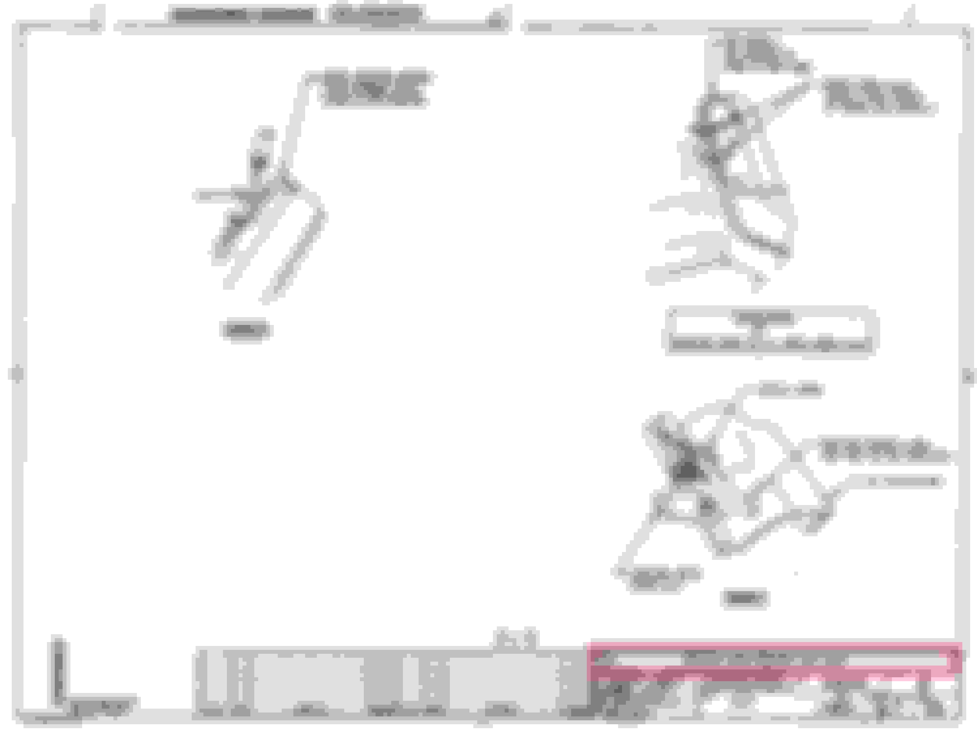
Tom, going back to the very first thing you posted on this thread, I found this in the 72 AM and thought it would be something you'd like to know. Those clips are definitely only for the Manual Transmission cars. Here are 2 scans. One is the bracket, and one shows the hose colors and connections on the AC
Note: I highlighted the text for SM cars. So that's one thing definitively answered for your 72 that has AT
Here's the layout for AC with all the colors labelled.
I've thought about that diagram a lot and it can also be read as saying that the positive battery cable is only routed across the valve cover on SMT cars, but not necessarily that the wire harness that runs across the same location without the positive battery cable don't use the same metal tabs for the plastic wire loom clips to go into. What do you think? There's another drawing on page 12-9 of the CSM entitled "Battery Cable routing A-Body" (Figure 12-16) and the restrictions of SMT and AMT specifically always refer to "cable" and say nothing about any other wires.
Do 1972 SMT cars have any other wires running alongside the valve cover, like alternator Also, I have that original-looking plastic clip wrapped into those wires that have to clip into something and I think those metal tabs look just right?...
Location: Edmonton, AB. And "I am Can 'eh' jun - eh"
Posts: 24,525
No other changes required for SMT or AMT cars other than the battery cable as the routing would interfere with the Z bar mount on the frame of the car for SMT. In other aspects the front wiring looms are identical and routed the same.
So would you agree then that the wiring loom clip I'm showing should clip into something Allan? I only have one clip left, but I would assume the second one got lost along the way. Are there any other owners of 1972 automatics with information on this?...
Location: Edmonton, AB. And "I am Can 'eh' jun - eh"
Posts: 24,525
My 72 is stock and it has no clips for the wiring loom. I have to wonder if that wasn't added by a PO to use with an SMT valve cover clip. Honestly, it makes sense to keep it off the intake manifold.
My 72 is stock and it has no clips for the wiring loom. I have to wonder if that wasn't added by a PO to use with an SMT valve cover clip. Honestly, it makes sense to keep it off the intake manifold.
Does your 72 have ATM and the harness is laying on the valve cover/ cylinder head without attachments?
Location: Edmonton, AB. And "I am Can 'eh' jun - eh"
Posts: 24,525
1. Yes to ATM
2. Yes, the harness is zip tied to a vacuum hose going to the TCS. My car isn't AC and the harness is on the Passenger side. I expect that AC cars the wiring to the Alternator simply was extended but follows the same routing? Here's a file picture from when I was doing the front end and replacing the carb.
Thanks Allan. Good pictures that help me with vacuum hoses although I don't know if I can see your large diameter hose from the Vacuum tank. I can see that it doesn't go to the manifold fitting by the distributor where mine fits although your first picture doe show a hose going from there to someplace else. I also noticed that you also have the idle speed solenoid used with the ATM and I'm going to re-install mine too, once I get the correct 4 barrel q-jet bracket from Scott. Why did you use the late model throttle bracket with the space for the extra cable? I can see that yours also doesn't have a hole for the throttle spring, just like mine. I'd love to know where the factory put them :-)...
Location: Edmonton, AB. And "I am Can 'eh' jun - eh"
Posts: 24,525
Tom, you won't see a hose to a vacuum tank because my car doesn't have AC. The throttle cable bracket is a repop, that's why the extra hole. If you look closely at the bottom 2 pictures, that hose goes to the top port of the TCS on my car. The other branch of that fitting is capped, but would be a vacuum source for AC white hose. I'm not happy with the HEI system on the car so I'm planning to pull it and reinstall the stock points system. Kept in good tune it's just as efficient as HEI, and the stock air cleaner will fit without any issues too
Location: Edmonton, AB. And "I am Can 'eh' jun - eh"
Posts: 24,525
Originally Posted by Vintage Chief
Kept in tune good? Why would it ever go out of tune? You have driven it "on average" - 70miles/year over 10 years. The stock points will surely get you up & down your driveway more efficiently w/ a stock air cleaner.
Norm, thanks for the rhetorical sarcasm. I have had significant life and health events that contributed to a stalled project, and I'm not sure how your comment is helpful or contributes to the Toms thread. My goal is to help Tom as much as possible with information I've gleaned through experience with my car. No reply necessary.
Norm, thanks for the rhetorical sarcasm. I have had significant life and health events that contributed to a stalled project, and I'm not sure how your comment is helpful or contributes to the Toms thread. My goal is to help Tom as much as possible with information I've gleaned through experience with my car. No reply necessary.
I apologize - only your comments are helpful contributions - how short-sided of me.
Kept in tune good? Why would it ever go out of tune? You have driven it "on average" - 70miles/year over 10 years. The stock points will surely get you up & down your driveway more efficiently w/ a stock air cleaner.
Ok guys. I'm going to get the water hose :-) ...
Thanks Allan. I should have remembered that you don't have Ac, but your description still helps. It also explains why your vacuum post doesn't have the thicker nipple... Maybe it's an optical illusion, but it looks like both of the nipples on your rear manifold vacuum port are capped. Only in your first picture there is a hose on it and I couldn't see where it went :-) So far, I haven't found a source for the correct molded in black hose with a white stripe, only painted on. As far as I can tell other colors only come into play behind the dash...
As far as the ignition goes, I only just got the car running again after repairing my fried wires, but I'm little embarrassed to say that I only discovered a few days ago that I don't have points anymore, but just some sort of magnetic or optical pickup and the standard coil which I'll keep for now.
Norm, it's amazing how little most of us drive our cars and yet something always seems to go wrong. My Mercedes 280SL used to need the points opened up every few months with regular use, but not really that much mileage. I still don't know why. I finally had enough and installed a magnetic trigger. I'll get back to the good info you posted earlier in a few days, but this week it was back to finishing the last bit of body work for now as I rebuilt the lower edge at the rear, left quarter panel. Waiting for one warm day in the next few weeks so I can shoot my epoxy primer...
Last edited by tcolt; February 13th, 2019 at 03:05 PM.
I've had some time to work on the Cruiser and things are coming together well now. I got a bunch of original used parts from Scott (Oldspackrat) and Inlinetube and they help finish things up around the engine bay.
Does anyone know if I attached the brake booster vacuum tube to the valve cover bracket correctly with the spring clip simply wrapped around the tube and the tab on the end of the bracket? Would the bracket have been painted along with the rest of the engine? If yes, were they assembled on the valve cover so that there was no paint beneath where the bracket mounts?
How about the plastic clip for the spark plug wires? It doesn't really seem like the clips do that much to keep the spark plug wires secure or tidy and what's the reason for the bigger distance between the last two cylinders on the driver's side clip?
Last edited by tcolt; February 23rd, 2019 at 11:58 AM.
Also, I installed the engine lift bracket, but it hits the manifold tube the way it's installed. Is it possible the washers should be installed as spacers beneath the bracket instead?
Location: Edmonton, AB. And "I am Can 'eh' jun - eh"
Posts: 24,525
Tom,
Can you please show a larger picture of the engine lift where you attached it to the intake manifold? It shouldn't need any washers and it shouldn't interfere with other parts. There's a good picture on page 132 (section 6-1) of the Assembly Manual.
 February 5th, 2019, 11:40 AM