When you click on links to various merchants on this site and make a purchase, this can result in this site earning a commission. Affiliate programs and affiliations include, but are not limited to, the eBay Partner Network.
Early-Mid 60's Perfect Circle Cruise Control Servicing
My ‘66 Starfire had a pretty bad speedometer needle flutter indicating some mechanical trouble in the cable system.
I dug around in my under-the-house junkyard and found parts from 4 other Perfect Circle cruise control units. 3 65-66 Big Olds + 1 65 or 66 Caddy. As a dedicated cannibalizer, I wanted to see if I could make 2 good ones from my dented, broken supplies. I've serviced 3 of these in the past week. I'm beginning to learn and thought I'd share, but only if anyone is interested.
Since Perfect Circle was a subcontractor, many parts swap from Olds to Caddy and back again. The main difference in the early 60’s years was the exterior arm that connects to the carburetor with a throttle rod. The arm shape & position varied because the physical positioning of the Cruise Unit in the engine compartments of different cars needed different shapes.
The early 60’s Perfect Circle units are electro-mechanical. As far as I know units like mine ended around 1968 or so. They were most common in Cadillacs, but can be found here & there on other GM makes. Up to 1966 the Caddy units are like Olds, but in 1967, they modified the design with a better connector & smaller design. GM settled on vacuum units in
the later 60’s which carried on until digital cruise units came in.
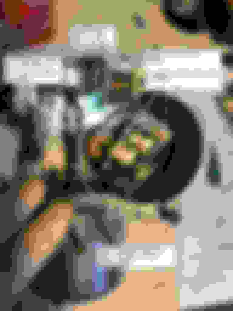
'66 Perfect Circle Big Olds (88/98) Cruise control units. Cover on in foreground, cover off in background. They do not interchange with Cutlass / 442.
There are 3 mechanical cables going into the unit: 1 from the front wheel; 1 to the speedometer head, and 1 Bowden cable which moves in/out responding to the drivers desired speed as expressed by the driver’s speed wheel.
Perfect Circle cruise control units have 2 mechanical inputs: front wheel, and speed control bowden cable. Plus 1 output to the speedo head.
Mechanically, the trouble spot usually seems to be the front wheel cable. It’s winds a convoluted path right by the driver’s exhaust manifold which melts off or breaks off the plastic insulation over time. Then the cable lubricant leaks out and the cable starts binding. The casing can also kink creating a spot where the inner cable rubs on the casing. This is one of the causes of the speedometer flutter. In extreme cases it breaks and unwinds itself inside its casing. That's a mess.
If you need to make a new one, the front wheel cable has a special tach drive tang on the cruise unit end which is a bit hard to find. I’ve soldered a few after cutting the cable to fit. The wheel end is the standard GM squared off wound cable. The speedo head cable is 35” long and standard GM stuff.
4 wires connect the unit to power, an special brake light switch, lock-in switch and 1 other.
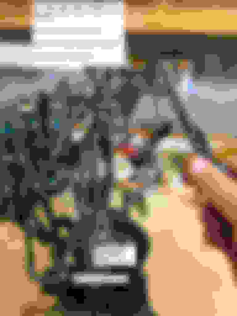
Electrically the big weakness in the design I’ve got is the electrical connector which is made of plastics. Most all I’ve ever seen have broken over the years in the tough environment of an engine compartment. I had 1 of 5 that was unbroken. Once it breaks into bits, some integral limit switches stop functioning and the wires don’t connect. Then what you have is a complicated speedometer. I've tried epoxying these before, but I think Krazy Glue may work better since it solves plastic.
Krazy glue can repair this terminal block, but its a design weakness that is tough to fix permanently.
Let's stop there for now. I've got full teardown and servicing photos, but am not sure it will be interesting to anyone. Is anyone interested in hearing more?
Yes please continue .
I admire anyone brave enough to tackle trying to get one of these units working .
These Perfect Circle units were truly the " pioneers " of cruise controls .
I’m happy to continue, but I don’t fully understand these units yet. I understand the mechanical connections, since, well, they’re mechanical. They pretty much tell you why if they don’t work.
The electrical connection details the far remain a bit of a mystery to me. The 66 Olds Chassis Service Manual is helpful, but there’s nothing I’ve found on the design (or theory) on how these parts are supposed to work together to create a speed control system. The CSM basically has you set the point gaps for the limit switches and the high/low points system and not much beyond except some basic field tests. That was smart for GM to control costs. I’ve burnt a day or 3 just getting into these things. In the 60’s, I suspect the fallback was “Oh heck, send it back to Perfect Circle”
But the technicians at Perfect Circle are long since retired, if not 6 feet under. And no one that I can find has posted anything on the ‘net. So it’s kind of archeology. What did the ancients know? How did it work? If a few people care, its probably worth burning a few hours to not lose the knowledge of these arcane, but cool systems.
So far, I’m focused on getting the speedo head to read correctly without fluttering, but I did put the cruise controls on there to see if I could get them to work. It’s intriguing to see 55 year old analog machines perform as designed.
Anyway thanks for the encouragement, I’ll carry on. Be warned: this may be like drinking out of a firehose.
I find your discussion very interesting as well. Although the optional (K30) cruise control system on my '69 4-4-2 is a different style, I found it almost impossible to find someone interested in working on it. It didn't work when I bought the car in 1987. When I went through the restoration process with the car in 2015-2016, again there wasn't much interest from anyone in even looking at the system. I dove into it myself earlier this year, trouble shooting all of the components using the CSM as my guide, and discovered I had a faulty brake switch and that the transducer didn't work. I quickly found a replacement original brake switch and I was able to get my hands on a replacement transducer. The cruise control system showed some signs of working, but it just continued to accelerate once I engaged the system. I finally found a business in Minneapolis called Cruisemasters that agreed to look at my original transducer and the replacement unit I had that almost worked right. They fixed them both (plugged vacuum tube in the replacement unit, bad solenoid in the original unit), plus they gave me the applicable pages of an AC/DELCO Cruise Control Systems Manual for what I have which has really helped me understand how the electrical portion and the vacuum portion of the system interact with each other.
For the first time in the 33 years I've owned the car, it feels pretty good going down the freeway and setting the cruise control in a car that I didn't even know cruise control was an option back in the day. It's an option rarely seen - I've never seen one on another car like mine and know of only one cruise control system like it installed on a '69 Vista. And your mid-60s cruise control systems - I wasn't aware that they were even available back then until your post showed up. Thanks for the details - it's interesting to see how those systems worked as well.
Randy C.
Last edited by rcorrigan5; October 3rd, 2020 at 10:00 PM.
Reason: add that I found a replacement brake switch
These units are very interesting. They use a centrifugal weight design to control a set of points that govern the motor direction (motor spins a worm gear attached to the internal assembly that is attached to the accelerator lever). The cable coming from the dash control applies more or less spring pressure to the fly weights depending on the position of the speed dial. More spring pressure and the fly weights must spin faster to keep the same position. The four wires coming into the unit are an ignition wire, an "on" wire, and two "set" wires. The ignition wire gives the unit power to run the motor the whole way to full throttle (basically just out of the way) whenever the dash switch is "off" and the vehicle ignition is turned on. This wire is run through the points on the connector. When the system is off, the motor runs until these points are opened. The "on" wire causes the motor to move the internal assembly based on vehicle speed and the speed dial on the dash. This is what allows the unit to function as "speed warning" as the internal assembly will not take control of the accelerator but will stop the accelerator pedal once you are at the set speed unless you push through the back pressure produced from the coiled spring on the accelerator lever outside the unit. The "set" wires engage the internal electro-magnet to allow cruise control and take over the accelerator lever. 1965-1968 units have two "set" wires coming in the unit. One runs through the brake switch (and clutch switch if you have a manual transmission). The other powers a small "latching" relay inside the unit that allows these unit to have an auto-resume function. Once the "set" wires are powered, the internal relay "latches" on until the unit or the vehicle is turned off. The "set" wire from the brake switch will momentarily break the connection to the electro-magnet when you hit the brakes to allow the car to stop accelerating, but because the internal relay has been latched, the magnet turns back on as soon as you let off the brake. This means that as soon as you reach the set speed and the internal assembly is once again near the accelerator lever, the lever will be "grabbed" by the magnet and cruise control will automatically resume. 1959-1964 units only have three wires and do not have the internal latching relay or the auto resume feature. In the earlier units, you had to re-set the system every time you hit the brake and were back at speed. Hope this makes sense.
Many thanks for your details on the theory and the scan. I will continue The '63 unit diagram is identical to my '66 unit. This is good since it helps us bound the limits of any advice we agree on.
I serviced another unit this morning. Third or 4th time through, it's not so daunting anymore.
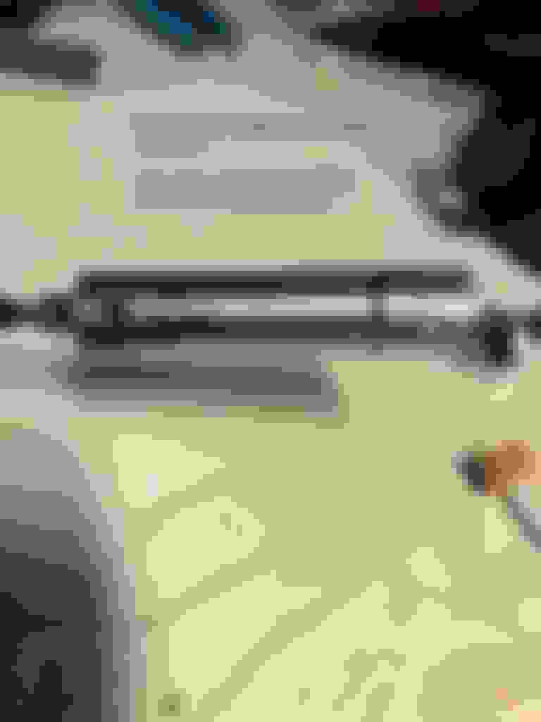
The big news of the day: I confirmed that my speedometer flutter was coming from my lower cable. The problem was in the wheel hub with the squared off interior that drives the lower cable. Mine had shattered leaving shrapnel inside the cable causing fluctuation. Also the wound cable was only engaging 1/4"- 3/8"'s vs the full 1 1/4" or 1 1/2" of the squared off part. So somtimes it worked great. Sometimes it fluttered.
The broken one is on the bottom. The good one (now on the car) is on the top. If your cable drive pin is snapped off short, your speedometer may flutter/fluctuate. Replace it with correct length if possible.
The other thing I learned yesterday is that if the spring nuts (3.885 above) on the cable drives, either the wheel cable, or the speedo head cable are not tight, the gears drop out of position, lock up and the speedo reads dead. New spring nuts are called for to be sure the gears will stay in place and work.
Hope that's useful. More soon on the guts of these machines. They are interesting.
That is great that you found the reason for your fluttering. In the picture below, you can see a partial 63 set up with the three wire transducer. These units were used from 1959 -1964 with various motor configurations and do not have the latching relay located inside the unit (small yellowish transparent plastic box mounted directly opposite to where the 4-wire connector mounts in your first picture). They also do not have the black and green wire running around the centrifugal fly weights as seen in your first pic. If you have a 4-wire unit, it is out of a 65 or later system. I have been servicing these units on Chevrolets and Cadillacs for almost 20 years, I am not sure when Olds adopted the perfect circle system, but Cadillac ran the system from 1959-1968 (as you stated earlier, the transducer design completely changed for the 1968 model year). Chevy ran the perfect circle systems from 1959-1966 (changing to a vacuum operated design in 67). Hope this information helps. As I said, I have been servicing these systems for a long time so if you have any questions, I would be happy to help. Also, one of the most common items to break in these systems is the plastic "rack " of teeth located in the speed dial control. In college I reproduced a run of about 65 of these out of ABS. The originals are made of nylon and get very brittle with age. Thread Tools s
O.k. Seems Some of you are interested. Let's carry on.
Disclaimer
If you follow this, please remember you're dealing with an automatic speed control that has the potential to kill you & your passengers if you get it wrong. For now mine are disconnected from my cars since I don't use cruise much and some of the driver control plastics are broken. I just think they're an interesting option. If I get confidence beyond the mechnical cabling, I may reconnect them but for now they're for show. That said, I don't think I'm too far from function and they have functioned in the distant past.
Here's a little illustrated theory which picks up on with the great comments from Loaded68W34 above: Governor weights translate turning front wheel speed into a force that the driver speed wheel selector works against by compressing the spring.
Once the cover is off as seen in the picture above, the next step is to remove the the speed selection plastic nut on the back side. You basically push the arm which holds the governor spring out, then unscrew the plastic nut. Then slide the spring arm (Compressor Rod above) & governor spring out of the housing. I reconnect the plastic nut when it's off the car just so it doesn't get lost. Speed selector cable recepticle doubles as a shaft retaining nut for the spring arm.
The next two pieces to are are the covers for the front wheel cable & speedo cable. It just takes a small flat blade to unscrew their 4 screws. Here you can see the slot for the wheel driven cable tang on the left, and the standard GM square cable receptacle on the right. The speedo cable is standard GM diameter. The wheel driven cable is a bit thicker. I believe in the neighborhood of .045". That lower cable is a pretty rare piece, you can easily remake the speedo head cable. Here's how to get the cable covers off. The speed selector recepticle on the upper left has already been removed. It's on the right in this shot.
Next I turn the unit back over since the covers and "trim" have basically all been removed and you can see how the parts fit together. You'll see a bunch of wires running all over the place. And probably your terminal block is broken. These all need to be disconnected before removing any of the magnetic parts, points and gears. Otherwise you're into soldering 50 year old stuff. Pay special attention to the yellow and the black wires that run around the pivot pin from the terminal block. Disconnect the wires before removing the guts. Take lots of pictures beforehand to be sure you know which ones go where for reassembly.
There are 3 screws on the side, partly buried underneath the spring loaded carbutertor arm which hold the armature in place. They'll need to be removed. This will be difficult if your carb arm doesn't rotate. The top screw is easiest to start with. On reassembly it works as a locating screw while you mess with the other 2 hidden under the carb arm. I use a small screw driver and sometimes ratchet the screws in or out by hitting them horizontally under the carb arm. 3 side screws retain the works inside the case If your carb arm is seized, this screw will be difficult to get at.
With wires disconnected and the screws loose, you can lift all the guts out as a unit. I put mine in a vise so I can use 2 hands to gently slip it up and out of the housing. It's slightly tricky since you don't want to bend or break anything old, rare and damn near impossible to find. Gently lift the left hand magnetic stuff and right hand cylinder out as a unit. They are joined by the small pivot pin in the midde.
Now that the gut are out, we can see the speedo and wheel cable gears. My goal was just lubricating these to get consistent speedo readings, I can't comment all that much on the electromagntics of it all. Now we can see the speedo head gear & governor weights clearly.
To lubricate the gears and get them running right, there 2 steps left to do: remove the governor and speedo head gear shafts. They're held in by bronze bushings which you can drive out if you _really_ want to go nuts, but I found just cleaning them thoroughly with Brakleen, qtips and a little steel wool worked well for me. Here's how the gears come out: Be gentle with these 50 year old spring washers. But be aware they can be replaced with new ones. The left size is .25" inner diameter. I didn't break my right one, so I don't know if its the same.
Governor gear/weights on the left, speedo gear on the right.
So that's basically the teardown.
At your option, you can aslo use a 3/8's open end wrench to remove and clean the electric motor, but I didn't want to get into that. I pulled it, taped over the holes and got the grease off with steel wool. In one of the pictures above, you'll see a warning about removing the jackscrew. I recommend against this since you can grease it easily without disassembly. And there are 6 tiny bearings which are very fiddly to get back into place if you do.
If you do take the motor off, it's just a few plastic spacers you need to remove before dunking the cover and whole housing in carb cleaner over night. This makes an especially clean unit after reassembly. The jack screw can stay in since its metal. With carb cleaner all the plastics have to come off, especially really old brittle ones.
I'll get to servicing and reassembly soon. Comments & suggestions on how to do a better job are most welcome.
Reassembly of '65-66 Perfect Circle Big Olds Cruise Control
Disclaimer
This is an automatic speed control unit. It has the potential to injure or kill you. This is all just to get the speedo working correctly.
Component Cleaning
I clean these with Brakleen, Berryman's B12 Chemtool, Carb cleaning bucket, long electronics q-tips, 800+ grit sandpaper, and #0000 steel wool. If the cover or housing is dirty, I take a dremel & wire wheel to it. I found interiors of these units spotless after 50 years.
Polishing out dirt & scratches
Between cleaning & relubricating I polish anything that spins with steel wool or sandpaper depending on scratching and finish I'm looking for. I polish both cable gear shafts with steel wool, & polish the bearings they spin in too.
New lubrication
Once polished, I relubricate with wheel grease, CFC Power Lube &/or White Lithium grease. I only use a touch of wheel grease on the jackscrew. After that it's Power Lube & a shot of lithium grease here & there.
The first parts to reinstall are the last out: the speedo gear, then governor gear. Give 'em a spin to be sure the spin freely.
Under the governor gear be careful with the ball bearing/washer assembly. Regrease it. Then be sure that the washer doesn't slip off as you reinstall the shaft.
Once shafts are in place, use a screwdriver to gently work the spring washers back on their shafts. If they bend, flatten them. If they break, the governor gear's spring washer inner diameter is .25". Spring washers should be tight to the shafts & snug enough to prevent vertical movement, but allow gears & weights to spin freely
The washers hold shafts in place vertically. They need to be tight with just enough housing clearance for the shafts to spin freely. Test it by flicking the governor weights with your finger. You should see several revolutions before they spin down.
Put the cable gear covers back on: Once you've spun tested the shafts, reinstall the covers
Servicing Motor Points
After 50+ years, motor points are generally pitted. Polish the points. Here's how to remove the low & high speed motor points. Note the spacing or gaps before you remove them so you know where to put them back. High & low speed motor points. Give 'em a polish for electrical connectivity
I polish points using a light hit with a dremel wire wheel. I aim for a flat polished surface with no carbon on the points. Lube before reinstall.
The factory did not consider pits on these points a problem.
Once high & low speed points are off, the points they connect to are exposed. Dremel these too - to get rid of old carbon & a flat polished surface. While you're polishing, clean the motor arm too. See the '66 Chassis Service Manual for point gaps under the "Accessories" section.
A carb arm & magnetic assembly shot. I remove the carb arm for cleaning. When reassembling, be sure to get the wave washer back in place: Reinstall the carb on on the main pivot shaft. Consider shaft polishing, be sure you have the wave washer on before putting this assembly back in.
Once you've got points polished, carb arm cleaned, & magnetic stuff reassembled, it can go back in the housing.
Preseat 3 housing screws so their ends are flush to the housing interior wall. They screw into the magnet's mount once it's back in. Preset these side mounting screws. They hold the magnetic assembly in place.
Next is the trickiest part. The governor spring retainer & jackscrew pivot points must be lined up to fit back in right & slip in as one unit. Here's a shot of the parts that need to slide in easily: Install the carb arm, magnet and speed selector cylinder as 1 unit. Take your time.
What's tricky is that the square thing with the U channel which retains the magnet pivot points needs to line up just right with those points & high enough so the governor cylinder goes onto its shaft. This may take a few tries. If it hangs up, spin the jackscrew square mount up or down to change the U channel position until it slips in easily. If the magnet pivot points don't fit, adjust the square thingy up or down on the jackscrew to get the angle right and try again.
When you have the unit seated, rotate the magnet's mounting plate to line it up with the screws you preset earlier. I do the tall screw 1st, middle 2nd, & finish with the 3rd (hidden) one. I use my tiny screwdriver going into the screwhead from the side, not the top. It's hard to get the carb arm out of the way.
If you pulled the reed switch, it goes back where it came from: above the speed selector rod, secured by one screw. Then connect the magnet green wire to start reassembling wiring Begin reconnecting the wiring by with this wire from the magnet to the reed switch
Next is the terminal block. I connect a few wires before screwing it back in to check & recheck pinouts. I start with the long yellow & long black wires that go to the back of the magnet: Route these wires carefully. Yellow on the right, black on the left, not crossed, but under the main pivot shaft.
Then I connect wires that come from the electric motor to the terminal block switches. Here are pinouts from various angles. After 50 years of hot/cold it crumbles like a bad cake. Use Krazy Glue to repair it and hope for the best.
Pinout with no wires attached. Don't quote me on wire colors.
I'm trying to err on the side of too much. But you knew that...
Lastly install the speed selector arm. The spring goes in 1st with plastic end up, then slip the arm through square housing hole. Lubricate the arm with Power Lube. Plastic gears in the driver's speed wheel work against it. They break after 50 years. Secure the arm with the speed selector nut. Secure the speed selector arm with this nut.
Here are terminal block electrical connections. Factory diagrams are unclear on which terminal is #3 vs #4. I labeled them with correct (for Olds) wiring colors. 50 year old plastic shell connectors disintegrate. When you replace shells, it's easy to switch the blue & purple wires. Head to the boneyard to find a replacement. GM used this shell shape into the 80's
Side view of the in-car connection In-car pinout with wiring color specifications. I checked these with my test light to be sure I wasn't wrong on the colors.
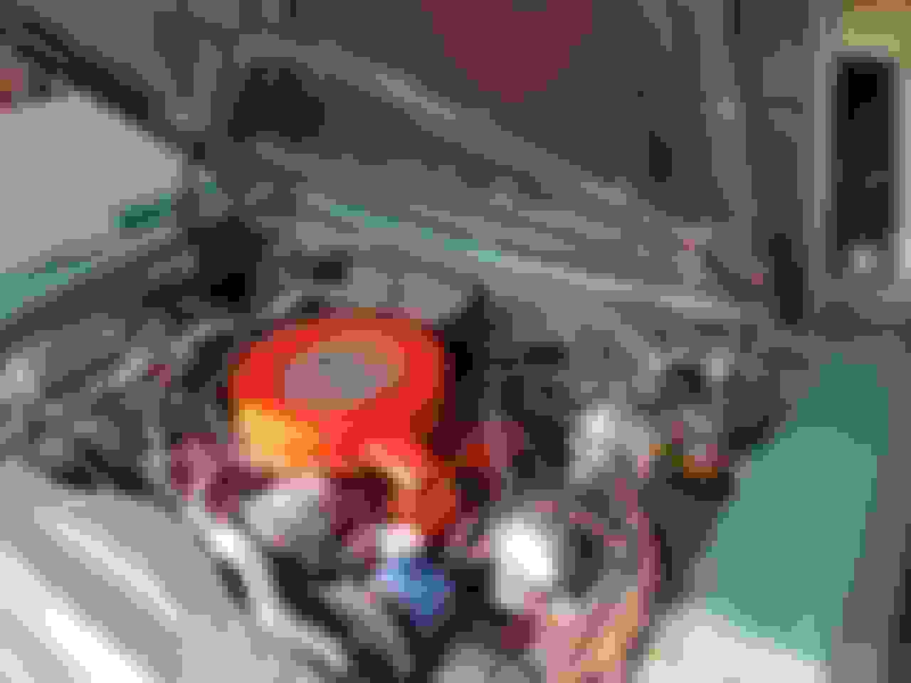
Dig this undocumented 65-66 Big Oldsmobile Perfect Circle Cruise Unit Interface. No books I have refer or even show this, but I found it along the way in a '65 or '66 big Olds looking as factory as the day the car was made.
I suspect this was used later in the model year when Olds might have found out from field service that their standard throttle controls were not holding up well under the added torque from the Perfect Circle Units. It seems aimed at increasing strenght, but wow, look at the mechanical complexity it adds!
Ever seen one of these on a mid-60's big Olds? I've only ever seen this one. So I pulled it...
The correct dimples for the firewall holes were in my 98 convertible, so I think it's factory. Anybody else have one?
Lots of rods. I refreshed this one today with a good cleaning, fresh cotter pins, & a few nylon washers to reduce the side-to-side slop
Here's a rear view:
Peak mechanical. No one will ever do this kind of thing with rods and cotter pins again. Cool.
Anyway hope you all enjoyed this all-too-deep dive into Perfect Circle Cruise Controls. It's been a fun few days digging into these crazy machines.
Comments, conjecure and suggestions most welcome. Especially on this weirdo piece.
Thanks for all the time and effort you have put into this thread. I think my 68 98 had this setup when I had it in the early 80's- it did work. I probably will never have another car with this cruise control but I find it interesting to follow along.
You’re most welcome for the pictures and what little I know about these devices.
Somewhere, sometime, someone may look up Perfect Circle cruise controls and find these posts useful. I mostly wanted to capture the logic for someone who is where I was years ago - curious, but ignorant of how to go about disassembly, servicing, & reassembly. I just don’t want anyone to think I’m an expert. That’s not true, I’m just an interested hobbyist.
The electrical switches are still a bit of a mystery to me. Mine have worked in the past, but their various maladies made them not work well. I’m working on that now. The big leap over the past few weeks was getting the 98 Speedo input to not waver/flutter. Once that input is good, I can work on the rest of it.
My problem right now is getting the drivers speed setting wheel and related Bowden cable to work. My speed setting wheel spins to freely to be doing anything at all to move the Bowden cable. I’ll have to disassemble it and figure out which plastics are broken. In the next week or 2 I’ll disassemble the dash speed wheel and start working on fixes.
Coda, for you music fans out there. The next chapter for me was getting the speed dial wheel working again.
My Speed Control wheel (dash control unit) has been non-functional for a while. Today I took it out to see if I could get the wheel to move the speed control cable once again. It was broken plastics as I suspected. The design is fine, but the plastic materials are brittle 50 years later.
Conceptually the speed wheel is a rack & pinion, where the dash wheel is a very large diameter control for the pinion gear. When the pinion spins due to driver action, the rack moves the Bowden cable in/out depending on which way the driver spins the speed wheel. Mechanically it’s like a slightly different heater control - both heater & cruise units use Bowden cables, the difference is the cruise has a wheel and the heater (at least in ‘66) has a slider.
My pinion & white plastic rack were fine, but the black track within which the rack slides was busted. I’d epoxied it a few years back, but that broke too. This time I KrazyGlued it after grinding out the old epoxy. And then I built a support from aluminum to hold the broken parts together redundant to the glue. I’m hoping it will work for a long time with a new better-sliding cable.
On the actuation side, I tried 2 old GM cables, but they were too kinked & too short. Kinked cables resist movement so much that they break the weak plastic control rack & pinion gear in the dash control. Too short cables mean the speed control Bowden cable can’t reach the main cruise unit. I had both problems.
I wound up making a new speed control cable from a Dorman 5’ control cable. It’s usually intended for choke cables or maybe a hood latch. It was pretty much cut-to-fit, with some tweaks I detail below.
My original cables were ~43”, but were too short for routing around my new dual master cylinder and other stuff. When I cut the new control cable, I added a few (3-4) inches to make the connection easy. I focused on getting the Perfect Circle cruise unit end right, reasoning that I could cut the other end to fit much more easily. The dash unit end of the Bowden cable is a very simple 90 degree bend to fit into the white plastic “rack”.
The hard part was putting the Perfect Circle cruise unit end on the generic spiral wound cable. The original cable was 11/64 OD, the new cable was 3/16”s OD, so I drilled out the Perfect Circle end by just a tick. Then I stuck the spiral cable in a vice and lightly slowly hammered the end onto the cable, with the sliding cable inside for strength. If you don’t leave the inner cable inside, most any hard push on the spiral outer cable just kinks it. Then you have to start over.
If you get the Perfect Circle end correct, the next challenge is bending the inner wire the right shape to fit inside the cruise unit speed control plastic nut. Basically I lined up old & new, then unused a couple of pairs of pliers to bend new like old. But it’s tricky too, since the inside of the plastic nut is actually keyed to accept the end of the control wire. So the bends need to be the right shape, length, and in 1 plane so that the rentention “bump” holds the Bowden cable in place and seats the keyed end inside the plastic speed control nut.
Happy to say that bench testing the new (longer) cable with the correct bends and correct end is wildly smoother than the old sticky chrome-flaking kinked factory stuff.
The key question is how much movement to permit on the inner cable. I can cut the dash end to fit, but I’m not quite sure how much movement to allow. Guessing 1.3 - 1.5” should do it, but I’ll know tomorrow.
Anyway that’s a start to repairing speed control wheels. Not mechanically hard, but 50 years on the materials they used aren’t as strong as I’d like them to be.
Just finishing this out. Here are the details on repairing the drivers speed control wheel. Let's start with the dashboard end of the cabling.
Here's what the unit looks like from the front, after you remove it from the car. The trim is missing, but here are the guts. The on/off switch is on the left, and speed wheel is in the middle. When reinstalling, the gray wire (courtesy lights) goes underneath and the blue on/off wire goes on top. Easy to mix these up... 65-66 Perfect Circle Big Olds speed control wheel and on/off switch. This is the dash unit.
Here's what the unit looks like from the top. Here you can see my not very pretty repair to the aged plastics. What's hard to see is the metal support I screwed in underneath using the existing hardware and their holes. No need to make more holes and further weaken 50 year old rare plastic parts. You can remove the entire plastic assembly from underneath the unit with just a couple of 1/4 hex head screws, then get at repairing it. The screw on top of the speed wheel is a "slip clutch" that allows the driver or mechanic to match the number on the dial front to actual vehicle speed, so the wheel number is accurate.
Beneath that big wheel is a little pinion gear which spins a bigger pinion gear that moves the white plastic "rack" inside the black plastic housing or track. I opened my "track" using an exacto knife to get at the parts inside. There's a spring steel spring which holds the pinion gear against the rack, the white rack itself which the bowden cable hooks into and the white pinion gear which links the speed wheel to the rack. I greased it all up and glued the housing back together with krazy glue. When testing, it's important that the slip clutch is back on snugly (the screw on top of the speed wheel) or the speed wheel will just spin on top of the pinion gear.
The interaction of the gear against the plastic rack is what creates the forward/reverse motion of the bowden cable here and in the main cruise unit itself. Perfect Circle Olds cruise speed control wheel from the top. The plastic pieces are weak after 50 years of use.
Here's what the unit looks like from the rear, you can see details of the repair and get a view of what I'm calling the "rack" in the "track"
Bowden cable connection to speed wheel in '66 Big Car Cruise unit.
The object of the exercise this morning was to get a new, longer, cable installed. I cut mine about 3" too long, but I think it will work. There's just more excess cable loop in the engine compartment, but that makes it easier to route too. For inner cable length, I was aiming at about 2" of travel to match the distance that the "rack" can travel in it's black plastic track. So I pulled the cable taught on the driver's end and cut it at about 2" and a bit leaving just enough to make the tooth that hooks into the plastic rack.
Yesterday I found that the replacment cable was 3/16"s, not 11/64" like Olds did. That meant that to fit the driver's end of the cable into it's plastic retainer, I had to shave down the sides of the cable housing just a bit. I hit it with a dremel & grinding wheel to flatten out the sides a bit and it went in with out too much fuss. The key thing was to not shove something oversize into 50 year old plastic. It would surely have snapped. Here's the driver's end of the cable, just before I ground it down: Replacment bowden cable for '66 Big Olds Cruise unit. This is the driver's end. The hook on the end of the inner cable connects to a hole in the white plastic "rack".
Turning to the other end of the cable, there are a few things to get the cruise unit end set up. As noted yesterday you have to drill out the Perfect Circle connector by 1/64" to 3/16"s to get the replacement cable to fit. Here's what it looks like when that is done: Cruise Unit end of driver's speed wheel cable. Perfect circle connector and specially bent inner cable which keys to the speed control nut.
Once you have this set up, all you have to do is screw the mechanical connector back on. I wound up cutting off a phillips screw real short to replace the one I'd lost along the way.
Perfect Circle drivers speed control connector. The wire inside cannot be seen here, but it's there.
The hard thing about this operation is being sure the bent wire is seated in it's key slot up inside the plastic speed control nut inside the Perfect Circle unit and mechanically retained by the "bump" which holds it in position. I wound up taking the front cover off the Perfect Circle unit and then moving the speed wheel to see if the governor spring was receiving the driver's wheel movement. It was.
I still don't trust the plastics much, but they seem to be working for now. A new unkinked cable, greased and better length should make them last a little longer.
Please remember I'm a rank amateur and this is a speed control. Don't take anything I've written here as safe for road testing.
Oh -- I think I know why Olds went to that goofy firewall support set up with the cruise units. Connecting the perfect Circle Cruise to the usual throttle puts a pretty large side load on the pot metal kickdown switch.
My guess is they had a bunch fail in the field and arrived at a stronger system after a while. Stamped and welded steel would take the side load and other strains much longer/better than pot metal.
Next step on the 66 Starfire: curing a cruise motor constant-running condition.
Something inside the system was causing the electric motor to run whenever power was supplied to the unit, whether or not the dash “On” switch was in on or off position.
I disassembled the dash switch, no problem there. Cleaned & reinstalled. Not much wear at all, just a bit of dried up lithium grease.
Then I suspected I’d color-blindedly mixed up the red & brown wires. Nope. I had my daughter ID the correct colors when I spliced in fresh wiring in place of the cracked, hardened old wires.
But the running condition persisted.
So dash switch was good wiring was good, that meant the problem was inside the cruise unit itself. Yup.
Turns out when I’d cleaned up the power contacts in the unit, I had not provided enough clearance gap (.025 +/- .005). Once I corrected the gap, it solved the problem.
I wish I were a more efficient trouble shooter, but at least I got it.
I should have started with the point gaps, and not bothered the dash switch. It’s a pain to remove and service.
Thank you very much CF for the full explanation of how this type of cruise control works. I found this thanks to your link in Misfire's request. The system is very interesting, and I agree about the comment of this being the peak of electromechanical complexity. After reading this, I am especially grateful the one on our 1966 Ninety-Eight LS works, which was pretty amazing to me. Perhaps the fact there is only 68,000 miles on the car, and, from history I have dug up, the car sat in dry and dark storage for perhaps 20-plus years, though I do know time takes a toll. When we got the car, it did not work, but by merely going on a whim, I cleaned what looked like tarnished connectors on the 4-wire connector you mentioned on the unit itself. It was, by the grace of things, a success. The speed reminder works, the cruise works, and I can increase/decrease speed by working the thumbwheel. How long will it last? Who knows, we only drive the car a couple hundred miles each year, now especially with Covid-19 restrictions against many car shows up to now. The car is in the barn right now, when we go up there, I will look closely to see if we have the updated kickdown/switch pitch/ throttle mechanism assembly, but I do think we have it because I noted that the thing looked like a Leonardo Da Vinci invention! I will be sure to take lots of pictures, for the car was pretty much unmolested, albeit a bit weathered as one can see of the switch/dial picture before tidying things up when we got it so I am sure all things are in original state. Cruise control 1966 Ninety-Eight
VistaBrat,
In case you get interested in another bit of Oldsmobile arcane knowledge, here’s a run down on the ‘66 big car (like your 98) switch pitch/kickdown switch.
This was a good design, but 56 years later, your brass switch contacts may have worn down from use. That thread is dedicated to servicing the switch, best as can be. The short version is you disassemble and clean it, then plop a bit of solder on the worn parts to re-establish good switch contact and function.
By the way, noticed you have the firewall cruise control stabilizer on your 98. I’ve seen no documentation on it, but concluded this might have been a field change. As originally designed, the cruise was connected to the upper hole on the throttle switch. That works, but to me it looks like it puts too much side load on the pot metal switch pitch/kickdown switch. I’ll bet a bunch broke in the field from 65-67 leading Olds to deploy the firewall support structure you’ve got. I’ve got one on my 98, but never saw another so on my ‘66 Starfire is without.
Enjoy the cars. If you have questions about the 98, I’ve had my convertible for 35 years or so and put a whole lot of miles on it. Plus the Starfire is mechanically almost identical, net of the frame & rear brake differences
VistaBrat,
In case you get interested in another bit of Oldsmobile arcane knowledge, here’s a run down on the ‘66 big car (like your 98) switch pitch/kickdown switch.
Enjoy the cars. If you have questions about the 98, I’ve had my convertible for 35 years or so and put a whole lot of miles on it. Plus the Starfire is mechanically almost identical, net of the frame & rear brake differences
Cheers
Chris
Thanks for the information Chris, once again so much appreciated! I figured with the complexity I remember with the tangle of metal and springs at the firewall, I now, confirmed by you, do have the updated parts. As for the Switch-Pitch unit, ours seems to function just fine, when the switch happens, we get pitched back into the seat! You can feel at once when this happens! I guess, with the lower mileage on the car, we have lucked out with stuff on the car, the accessories have been trouble free save for some broken wires for the power windows, since repaired. I have an extra round switch for the kickdown/pitch which I have for another 66 Ninety-Eight I will be taking on, when circumstance allows. I will look at the included thread, for sure I will ask questions about the large Oldsmobiles as they come up!
My ‘66 Starfire had a pretty bad speedometer needle flutter indicating some mechanical trouble in the cable system.
I dug around in my under-the-house junkyard and found parts from 4 other Perfect Circle cruise control units. 3 65-66 Big Olds + 1 65 or 66 Caddy. As a dedicated cannibalizer, I wanted to see if I could make 2 good ones from my dented, broken supplies. I've serviced 3 of these in the past week. I'm beginning to learn and thought I'd share, but only if anyone is interested.
Since Perfect Circle was a subcontractor, many parts swap from Olds to Caddy and back again. The main difference in the early 60’s years was the exterior arm that connects to the carburetor with a throttle rod. The arm shape & position varied because the physical positioning of the Cruise Unit in the engine compartments of different cars needed different shapes.
The early 60’s Perfect Circle units are electro-mechanical. As far as I know units like mine ended around 1968 or so. They were most common in Cadillacs, but can be found here & there on other GM makes. Up to 1966 the Caddy units are like Olds, but in 1967, they modified the design with a better connector & smaller design. GM settled on vacuum units in
the later 60’s which carried on until digital cruise units came in.
'66 Perfect Circle Big Olds (88/98) Cruise control units. Cover on in foreground, cover off in background. They do not interchange with Cutlass / 442.
There are 3 mechanical cables going into the unit: 1 from the front wheel; 1 to the speedometer head, and 1 Bowden cable which moves in/out responding to the drivers desired speed as expressed by the driver’s speed wheel.
Perfect Circle cruise control units have 2 mechanical inputs: front wheel, and speed control bowden cable. Plus 1 output to the speedo head.
Mechanically, the trouble spot usually seems to be the front wheel cable. It’s winds a convoluted path right by the driver’s exhaust manifold which melts off or breaks off the plastic insulation over time. Then the cable lubricant leaks out and the cable starts binding. The casing can also kink creating a spot where the inner cable rubs on the casing. This is one of the causes of the speedometer flutter. In extreme cases it breaks and unwinds itself inside its casing. That's a mess.
If you need to make a new one, the front wheel cable has a special tach drive tang on the cruise unit end which is a bit hard to find. I’ve soldered a few after cutting the cable to fit. The wheel end is the standard GM squared off wound cable. The speedo head cable is 35” long and standard GM stuff.
4 wires connect the unit to power, an special brake light switch, lock-in switch and 1 other.
Electrically the big weakness in the design I’ve got is the electrical connector which is made of plastics. Most all I’ve ever seen have broken over the years in the tough environment of an engine compartment. I had 1 of 5 that was unbroken. Once it breaks into bits, some integral limit switches stop functioning and the wires don’t connect. Then what you have is a complicated speedometer. I've tried epoxying these before, but I think Krazy Glue may work better since it solves plastic.
Krazy glue can repair this terminal block, but its a design weakness that is tough to fix permanently.
Let's stop there for now. I've got full teardown and servicing photos, but am not sure it will be interesting to anyone. Is anyone interested in hearing more?
Hope this helps some of you
Chris
Thanks Chris!
I just bought a complete setup for my 1965 Oldsmobile Starfire. The fella pulled every piece and part but found a couple of issues. First the cable from the thumb wheel to the unit a plastic tab that holds the cable broke and second the end of the lower speedo cable broke off where it goes through the front hub. The tip of the cable where it attaches to the dust cap broke off. Are there any repair resources for these? Your posting will really help.
The thumbwheel cable is a weak spot, mine don’t work either. There is someone in the thread above who has reproduced the plastics, but you’ll need to custom make a Bowden cable to the correct length with the correct bent ends. I bought a generic cable (used for a carb choke, I think) but haven’t gotten around to modifying it to fit.
For the wheel end of the cable with the special driving hub, this part is not unique to the cruise system. It was also used in most every big olds from 65-66, cruise unit or not (very few had cruise units, so really just any big olds). If you can’t find one from 65-66, other years might work - say 63-64, or perhaps later big olds too - up to 1970. They won’t be impossible to find, but you’ll need to find a junkyard specializing in old cars that just happened to have the right vintage Olds around.
As a suggestion, check the Arizona yards, also check French Lake Auto Parts in MN with a phone call. The nylon insert that drives the cable ages and is critical, you might want to consider a spare just to have one on hand. I have no idea as to cost, but since it’s such a critical part, now getting harder to find I wouldn’t mind paying anywhere from $20-50 for just that little piece. Without it, you speedo just won’t work.
I came to the forums this evening looking for a fuel tank for a friend's full-sized 1970 Oldsmobile and for some unknown reason, your article about Cruise Control also came up. Since I have a cruise unit in my 1962 Chevrolet the article was of great interest. Mine is still working, but is difficult to get it to "catch" and your write-up gives me the courage t dig into it. One thing that I can add is that when you have points in almost any unit that have a tendency to burn and stick, I have found a product that will help to end the arcing that causes these problems. It is a paste called "MG Chemicals 847 Conductive Assembly Paste, 1 oz jar $40.98 on Amazon. Just use a toothpick to put a small dot onto the contact of the points and it eliminates arcing of the points. A 1 oz jar is more than you will ever use in a lifetime, but it will save you a lifetime of problems with burned points. I used it on the power seat switch on my 1962 which was constantly giving me grief because it seldom got used and the switch points wouldn't make good contact.
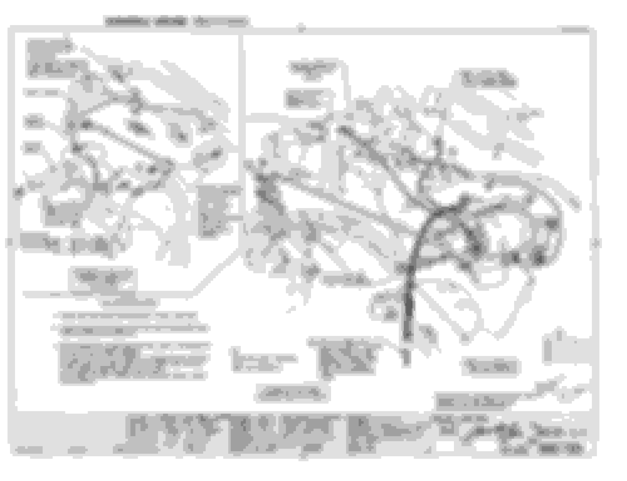
Just a couple of quick factory diagrams for this old thread.
First up, here's how the factory mounted all the engine side components. More or less they bolted it on to the driver's side inner fender in a position just forward enough to all the throttle rod to do it's full travel on the throttle switch. From the 1966 Olds Assembly Manual.
Next up, here's a rear view of the dash components. My dash components are not working right at this time. Note that this page does not refer to the all important second brake switch that turns the system off in case of driver braking intervention.

 October 2nd, 2020, 01:38 PM