When you click on links to various merchants on this site and make a purchase, this can result in this site earning a commission. Affiliate programs and affiliations include, but are not limited to, the eBay Partner Network.
Thanks. Just peculiar as an in-line fuse is generally placed on the power side - although, I guess you could argue the negative coil terminal is actually the power wire for the coil signal to the tachometer (which it is).
And for ref I did have the ground hooked to ground, I was taking images during the uninstall. When I get home (after I coach my sons baseball team tonight) I'll pull the tach completely out and see if I can get the other 2 gauges to illuminate.
** BTW thanks for helping me on this and all of the suggestions thus far **
1. I have the fuel gauge pod and the speedometer gauge illuminating properly now - had to add a better ground to the ground strap of the dash.
2. I think this Aftermarket tach is not correct.
When i connect 12v to clock and then the gray lamp wire to lamp - lights on 100% of the time and clock works - no ground wire
If i then pull light switch to open - lights out out in Tach but come on for fuel and speedo
When I swap the wires and place 12v on Lamp and the lamp wire to clock....I get lights 100% of time and clock works - no ground wire
If i then pull light switch to open - lights out out in Tach but come on for fuel and speedo
When I ground to the body of the tach - all lights go out - clock still works
If i do just 12v to clock and i ground to body of tach - clock will work
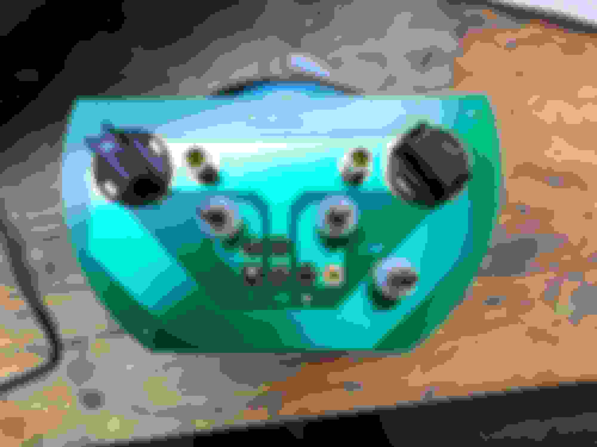
here are some visuals of the ground wire add and the tach... ground wire added should something be here ?
It's late here and time for sleep. But, I'll venture one question & suggestion before retiring.
During the above stated tests you just performed - if you never blew a fuse in the fuse box under the dash, then your issue is not with any of the constant hot lead wires (orange) and not with any of the headlamp/dash illumination (gray) wires. If your issue was on the positive wires, you should have blown a fuse. I'm suspecting your issue is contained within the ground wire(s) somewhere.
In both scenarios you tested above when you switched the 12V to clock & gray to lamp and then reversed them - you stated you had illumination with no ground. It's impossible to get illumination and/or the clock to work with no ground. Think about this a minute. There is no possible way in which you can complete any electrical circuit (whether it be AC or DC) without a ground. You must have a return (ground) to Earth. That is a fact. Without a ground you have no illumination, and you have no clock, and you have nothing in fact. So, you have a ground SOMEWHERE in some manner but it apparently isn't the CORRECT manner. Again, if the issue was on the positive wire feeds, you'd blow a fuse. If you aren't blowing a fuse, then it's on the ground side. And, since you have lights and clock working with NO GROUND, that is impossible because you can't complete a circuit with no ground. Start troubleshooting your ground wires.
Question from your very first post. You stated this:
I let the orange power feed for the clock touch the braided ground wire of the tach feed and boom - courtesy light went out.
I've been under and inside my dash many times. Honestly, I've never found a BRAIDED ground wire.
Are you talking about the braided wire of the wire harness for the tach? I thought that was a shield for radio noise and not the primary ground path as Joe indicated. If that's the case, then based upon your first indicated issue, when you placed the orange (constant hot) wire across the braided strap (the one from the tachometer I assume) BOOM - courtesy light went out and you blew your block to chassis ground connection (i.e. car would not start and IGN had no signal). I'm not completely sure what courtesy light you're referring to when you say courtesy light. And, I'm not clear on where you hooked up the braided ground strap initially. But, the source of your issue began with that braided ground strap when you touched a hot lead to ground. So, start looking at where you had or have that braided ground strap attached which isn't supposed to be a primary ground for the tachometer. The dashboard instrument panel ground circuit board is the primary ground.
Time for sleep.
Last edited by Vintage Chief; March 6th, 2019 at 08:58 PM.
I've reviewed several pictures of that braided noise suppression strap which surrounds the negative coil wire in-line fuse wire. The one end is a closed loop with no eyelet or connector. The opposite end has an eyelet/connector. Where was this braided noise suppression strap attached to your vehicle when you hit it with the hot orange wire and blew the block to chassis ground? Was it connected someplace? Was it just laying about on the dash but touching the chassis/dash/body at some point? It had to be one or the other since that's where you created an ARC to ground and blew your initial ground.
Where you have the black lead clipped on may not be a solid ground, clip it on the gold stand offs on top next to one of the lights. Where you have the red lead clipped on, it needs to be connected to a gray instrument lighting wire. The terminal that has the S under it is the tach and needs to be connected to the wire that runs to the coil- terminal. Last the terminal with + under it needs power all the time for the clock. The braided shield wire connects to ground.
BTW, just for some clarity - refer to the headlamp switch as pulled out into the ON position. Using the term open isn't a good one at all. Since, in reality, when you pull that headlamp switch out into the ON position, the circuit is CLOSED forming a complete circuit. It just is more meaningful when discussing electricity. ON means a closed circuit, OFF means an open circuit. When you turn a switch to ON you close the circuit to form a continuous loop. When you turn a switch OFF you open (break) the continuous circuit loop.
Where you have the black lead clipped on may not be a solid ground, clip it on the gold stand offs on top next to one of the lights. Where you have the red lead clipped on, it needs to be connected to a gray instrument lighting wire. The terminal that has the S under it is the tach and needs to be connected to the wire that runs to the coil- terminal. Last the terminal with + under it needs power all the time for the clock. The braided shield wire connects to ground.
Eric?
Look at the terminal posts top and bottom. The S is to Battery, the + is to negative coil. Notice the posts, read the post description from the top-side enclosure where they are labeled.
I'll tell you that blasted braided (shield) wire is a loose cannon, IMO. It is not the primary ground for the tachometer (as Joe previously posted). It's nothing more than a radio noise suppression shield. Notice the one end of the braided shield wire is a closed loop end with no eyelet and no connector and the opposite end has a connector/eyelet. A ground wire would have two connectors one at each end. This cannot be ground wire because no end is connected to the tachometer to provide a ground to complete a circuit - the one end is DEAD. It may connect to a GROUND someplace, but it isn't the ground for the tachometer.
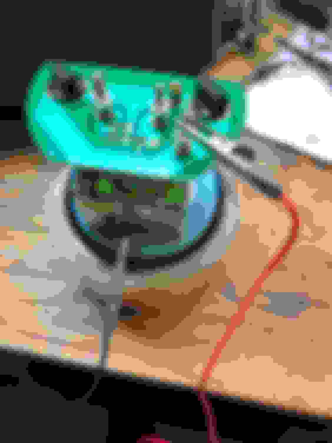
Ok so here is a few more photos and a video...see if we can figure this out.
1. test light photo shows that gray wire for lamps has power when light switch is pulled open (Closed circuit as mentioned above) ** No illumination when unit is grounded but again power is going to the unit as you can see.
2. Shows dash gauges illuminating and power going to tach for lamp while tach is grounded...still no illumination
3. Video showing what happens when 12v connected to clock side and i add and take away the ground - No illumination when light switch pulled open....ONLY illuminates when NOT grounded
**** Im wondering if i need to nix this particular gray feed and tap into the one from the speedometer as i know its "working" and grounded in such a way that its "working" ?!?!?
Last edited by Brians1; March 7th, 2019 at 03:39 AM.
TEST ONE
(1) Remove all wires from tachometer. Do not use test light for this test.
(2) Test/Demonstrate all dashboard lights work correctly - light switch pulled out all lights illuminate and light switch rheostat turned in both directions lights dim/brighten, and CCW turn beyond click courtesy lights come on.
(3) Test/Demonstrate all dashboard lights turn OFF when headlamp SW pushed IN. RESULT:
TEST TWO
(1) If TEST ONE is successful, place test light negative lead wire to known good ground (e.g. the exact same ground point used for all the dashboard lamps since it is a known good ground if TEST ONE is successful).
(2) Place test light positive lead wire on the gray wire being used to feed the tachometer - DO NOT place this wire on the tachometer. This is an independent test of the gray wire.
a) With headlamp SW pulled OUT - does the test light illuminate? RESULT:
b) With headlamp SW pushed IN - does the test light illuminate? RESULT:
So i tested all of that last night - here are results: TEST ONE
(1) Remove all wires from tachometer. Do not use test light for this test. - Completed
(2) Test/Demonstrate all dashboard lights work correctly - light switch pulled out all lights illuminate and light switch rheostat turned in both directions lights dim/brighten, and CCW turn beyond click courtesy lights come on. - Completed - 100% Pass of test
(3) Test/Demonstrate all dashboard lights turn OFF when headlamp SW pushed IN. - Completed - 100% Pass of test RESULT:
TEST TWO
(1) If TEST ONE is successful, place test light negative lead wire to known good ground (e.g. the exact same ground point used for all the dashboard lamps since it is a known good ground if TEST ONE is successful). Completed
(2) Place test light positive lead wire on the gray wire being used to feed the tachometer - DO NOT place this wire on the tachometer. This is an independent test of the gray wire. Completed
a) With headlamp SW pulled OUT - does the test light illuminate? RESULT: YES
b) With headlamp SW pushed IN - does the test light illuminate? RESULT: NO
"Rally Gauge Installation If your car did not originally come with Rally Gauges, you will need to reposition most of the wires in the factory terminal housing that are connected to the old Telltale (warning light) cluster. You will also need to cut or remove one wire from the steering column harness."
** I already did the re-wiring for the Fuel/Temp/Bat and replaced with proper sending units - its 100% functional **
"6. Remove or cut wire from Steering Column Harness. Locate the connector shown in Figure 2. This connector is up near the top of the steering column under the dash. It will be necessary to unclip and reposition the ribbon cable from the bottom side of the steering column to gain access to the connector shown in Figure 2. Once the connector is located, cut and insulate both ends of the green wire leading to the connector, or remove the connector plug and remove the green wire from the housing and insulate."
Could this be my issue ** I didn't have install instructions **
Therefore, you have a known good ground and a known good gray wire positive lead controlled via the headlamp SW based upon TEST ONE & TEST TWO.
TEST THREE:
With no wires connected to the tachometer except the following:
(1) Attach a black (jumper) ground wire from the known good ground contact point of the dashboard instrument panel ground circuit board (which you have already established as working) to the tachometer metal bezel (which is the ground point for the tachometer).
(2) Attach the known good gray wire positive lead controlled via the headlamp SW (which you've already confirmed as a known good gray wire) to the tachometer terminal post labeled LAMPS.
Do the lamps inside the tachometer illuminate? RESULT:
Could this be my issue ** I didn't have install instructions **
I have no idea if this could be your issue. I read it briefly.
I'm becoming confused here. Did you not state in your Post #1 all was well?
"Addded rally pack gauges to my 72, all was well, took it for a drive. Disappointed in the illumination I pulled the gauges to add LED bulbs.
Well...I let the orange power feed for the clock touch the braided ground wire of the tach feed and boom - courtesy light went out.
I went to just simply change the fuse but its good...all fuses are good...and still no power. No power at ON either from key."
It's unclear to me why you would want to move forward with a complete rewiring of your wiring harness if in fact you already confirmed and stated......"all was well".
If all was well, and you created a short somewhere by crossing the orange with that braided wire and things went array - why would you rewire your entire wiring harness?
TEST 3 produces a NO - the lights ONLY illuminate when 12V power is applied to the Clock side and NO Ground applied and the Gray Lamp feed is also connected, If I ground the tach the lights no longer illuminate and when the light switch is pulled Open, they still do NOT illuminate.
I also did a Test 4 --> - Gray to Lamps, 12V to Clock, NO Ground - Tach is illuminated --> I pull the light switch to Open and the tach lights go out immediately (No illumination) and the remaining 2 gauges in the dash illuminate as expected. ** If I ground the Tach as mentioned above lamps NEVER come on for test 3 and 4
Stop wasting your time with any "no ground" testing. That is not a useful test. When you remove the ground wire, you end up grounding the unit though the illumination circuit. That's why it goes out when you turn on the lights.
Run a ground jumper from the metal instrument housing to a known good body ground and leave it there. Now conduct your power-on testing.
All right guys break out the beer and the whiskey problem is solved !! And I’m kind of ticked at how...
it was the orientation of the LED bulb!!! I pulled one bulb out at a time from the tach and noticed that with one not in there it worked as expected. I put the second one in and it stayed illuminated. So I took the bulb pulled it out, rotated it, put it back in Boom... problem solved
All right guys break out the beer and the whiskey problem is solved !! And I�m kind of ticked at how...
it was the orientation of the LED bulb!!! I pulled one bulb out at a time from the tach and noticed that with one not in there it worked as expected. I put the second one in and it stayed illuminated. So I took the bulb pulled it out, rotated it, put it back in Boom... problem solved
I would not have guessed this was the issue. Evidently the LED lamps you're using have a specific orientation and you're saying one was oriented the opposite of the other?
If you could, would it be possible for your to post a manufacturer, part number and picture of the LED lamps you used? It could be beneficial to users who search the CO forum and are attempting to resolve the same issue.
items regarding these bulbs. Go To time point 2:05
And, as is clearly stated on the instructions of the bulb "remove rotate and reinstall"....as, the bulbs are polarity sensitive.
Often pays to follow the directions!
Last edited by Vintage Chief; March 7th, 2019 at 05:10 PM.
All right guys break out the beer and the whiskey problem is solved !! And I�m kind of ticked at how...
it was the orientation of the LED bulb!!! I pulled one bulb out at a time from the tach and noticed that with one not in there it worked as expected. I put the second one in and it stayed illuminated. So I took the bulb pulled it out, rotated it, put it back in Boom... problem solved
Ive been following this thread from the start and deep down inside I wondered if it was the bulbs, but what would be the odds? In the time I've had my 72 Supreme I have come across various electrical head scratchers that I have beat my head against the wall trying to solve when in the end it was the simplest, most obvious solution.
Sometimes the easiest problem is the hardest to diagnose, but I'm happy to hear you'll be able to sleep tonight😀
On this 1971 CS I own the very first issue I troubleshot was an interior electrical wiring issue. I not only found one, but two electrical issues.
The first one I was completely baffled. Ran all of my tests. Short story. Courtesy lamps worked backwards. PO (or someone or some place) installed a SINGLE CONTACT bulb into the rear passenger side armrest (TWO CONTACT receptacle) courtesy lamp holder which required a DOUBLE CONTACT bulb. Doh!
Last edited by Vintage Chief; March 7th, 2019 at 05:32 PM.
Brian, it isn't my intent to flame you in public, but it does demonstrate the need to follow directions. We've all been there. Thanks for the follow-up. Enjoy your beer & whiskey!!
Trust me I’m a humble guy - no offense is taken - when I took the pic I didn’t even look at what it said.
my default was take bulb out, plug in, and go...
I have a C6 vette and the polarity thing is real in that they won’t light up unless rotated...never seen where they stay illuminated ?!?...
actually this was just a test and I knew it all along ...wanted to just stump you guys
Psssshhhhhh LOL - gah all this over a light bulb and the inside package
 March 6th, 2019, 10:30 AM


")