When you click on links to various merchants on this site and make a purchase, this can result in this site earning a commission. Affiliate programs and affiliations include, but are not limited to, the eBay Partner Network.
I removed the original oil pressure and coolant sensor from my 64 Jetstar 330. I'm installing new mechanical gauges instead of the idiot lights. Now my question is i pulled the original wiring from the sensors through the firewall and I wanted to completely remove it. However I see it goes in behind the speedometer to a bulkhead. Can I just cap the wires off short and leave them hanging behind the dash. I dont want to mess with the bulkhead. Also I'm finding some random wires not hooked up just assuming there for a higher option car.
Yes you can just cap and stow the wires that you removed. Not sure of the extra wiring as anything is possible with these old cars. The extras could also be from past mods done by previous owners.
Also I'm adding an hei distributor as I've talked about before. I traced the fiberglass resistor wire back and it is soldered to 2 yellow wires do I simply replace the resistor wire with regular wire and resolder to the 2 yellow wires.
Also I'm adding an hei distributor as I've talked about before. I traced the fiberglass resistor wire back and it is soldered to 2 yellow wires do I simply replace the resistor wire with regular wire and resolder to the 2 yellow wires.
Yes, just replace the cloth-covered resistor wire with regular stranded copper back to that splice joint. And yes, that is factory. The gauge wires are simply providing the ground side of the circuit to the two idiot lights. Just tie them up and forget about them. To be honest, you should run a tee fitting at the oil pressure sender and keep the light. After the first week you won't be checking the gauge often and having a bright red light come on is a good backup. It's also a good idea to reconnect the temp switch, but this one needs to be screwed directly into a port and your intake likely doesn't have another available opening.
Ok, I guess they do solder on the pre 65's. One yellow wire goes to the fuse box and the other comes from the ignition switch for running power as a supply to the resistance wire from the ignition switch. There should also be a black wire that comes from the ignition switch to your coil+, it also needs to be connected to the HEI batt terminal. Remove the the resistance wire and solder a 12ga in its place and run it to the HEI batt terminal with the other black wire. The tan wire on the coil- side needs to connect to the HEI tach terminal.
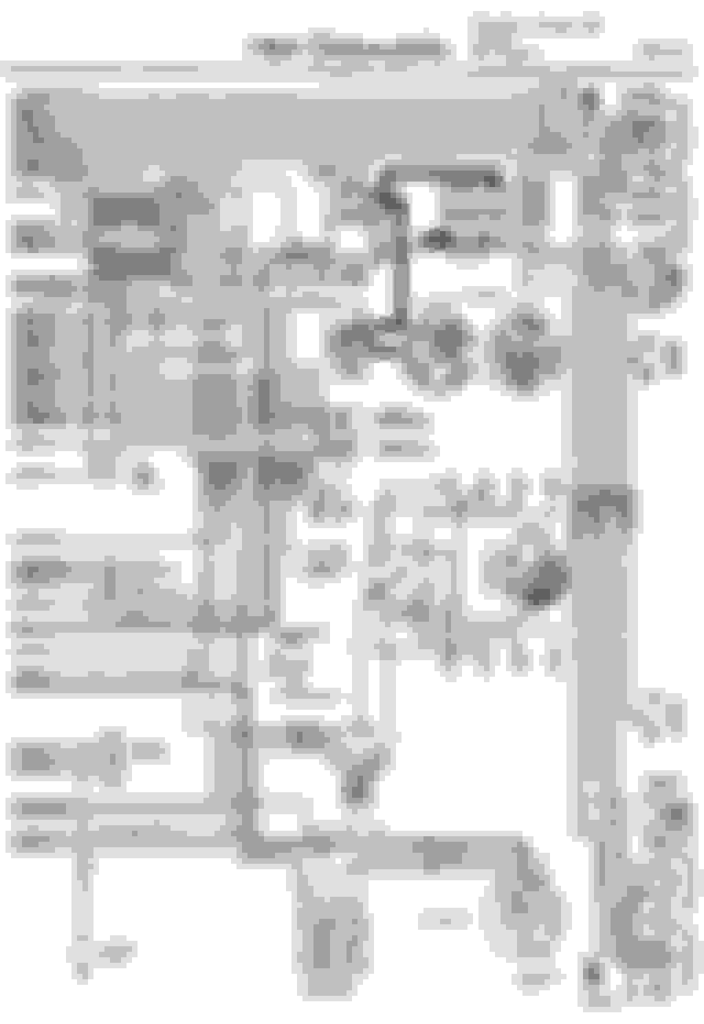
Also on post-65 cars. Look at the schematic for a 68, for example (I just happen to have that CSM at hand). The orange wire that provides unswitched power to the clock and courtesy lights has several splices in it. Granted, GM tried to make the splices at terminals where possible, to minimize this inline soldering.
One yellow wire goes to the fuse box and the other comes from the ignition switch for running power as a supply to the resistance wire from the ignition switch.
Yes, but to clarify, the yellow wire is switched 12v power out of the ignition switch. The splice splits off the resistor wire to the coil, while the other yellow wire feeds this switched 12v into the fuse box, were it feeds the turn signal, transmission kickdown, and instrument/backup light fuses.
Looking at these schematics it does not show if wires have tracers on them. I have a yellow wire with black tracer and a pigtail. not sure where this goes.
Looking at these schematics it does not show if wires have tracers on them. I have a yellow wire with black tracer and a pigtail. not sure where this goes.
Which is yet another example of why you need a FACTORY ORIGINAL service manual and not some off-brand copy.
 September 6th, 2017, 07:27 PM