
Generator Alternator Swap, wiring question...
 July 19th, 2010, 10:33 AM
#1
Registered User
Thread Starter
Join Date: Jul 2010
Posts: 23
Generator Alternator Swap, wiring question...
Hi everybody!! First post on here, and I'm sure it will be one of many. My uncle passed away, and left me his 1955 324 rocket. It was a project car for him, and he never got a chance to even start on the restoration.
The car ran fine, but recently the generator seized. This snapped the belt, and has left me with no way to run her. I want to upgrade the generator to an alternator. I was looking at this one:
http://www.summitracing.com/parts/PWM-282051/
I'm not sure what might need to be done to get this installed. The old one has multiple wires, and I believe this is has one wire, and is internal regulated. Any one have any help or wiring diagrams I could use?
 July 19th, 2010, 12:16 PM
#2
Old(s) Fart
Join Date: Mar 2007
Location: Northern VA
Posts: 48,229
The PowerGEN is a nice product. It comes with complete wiring instructions. You may find more info from the manufacturer's website instead of Summit:
http://www.powermastermotorsports.com/powergen.html
Note that they are available in black as well as chrome. Also, they are sold by many sources, so shop around.
http://www.powermastermotorsports.com/powergen.html
Note that they are available in black as well as chrome. Also, they are sold by many sources, so shop around.
July 19th, 2010, 01:57 PM
#4
Old(s) Fart
Join Date: Mar 2007
Location: Northern VA
Posts: 48,229
PowerMaster is the only vendor I know of who is selling alternators in generator clothing. Of course may sources will rebuild your stock generator, or you could replace it with a modern alternator. The latter will require some custom fabrication of brackets but the wiring is no different than for the PowerGEN. Basically you remove the old generator and regulator. There should be a heavy red wire from the regulator to the terminal post on the horn relay and a smaller brown wire that goes to the idiot light. On the three wire GM alternators, connect the red wire from the plug to the threaded post on the alternator and then connect that post to the post on the horn relay. The other wire on the alternator is brown and connects directly to the brown wire that was connected to the regulator. That's it. I just did this swap on my 62 F-85.
July 19th, 2010, 02:50 PM
#5
Registered User
Thread Starter
Join Date: Jul 2010
Posts: 23
Thanks for all the information! I'm still debating on one of the PowerGens, or just a basic one, and fabricate a bracket. Wasn't sure, so I double checked the generator to make sure it was a 12V system. She needs so much work, I might just go cheap for now. Thanks again, I'll take pics as I go and post them...
July 23rd, 2010, 09:10 AM
#6
Registered User
Thread Starter
Join Date: Jul 2010
Posts: 23
I know I sound like a complete rookie here, for good reason.  If I was to purchase a 3 wire alternator, is there a specific type I'd need to get?? I know there are positve ground, and negative ground GM 10Si alternators, as well as different output amperages. I've also heard of resistance needed from the idiot light to the alternator, to excite it at lower rpm's. Thanks for your patience, and information!
If I was to purchase a 3 wire alternator, is there a specific type I'd need to get?? I know there are positve ground, and negative ground GM 10Si alternators, as well as different output amperages. I've also heard of resistance needed from the idiot light to the alternator, to excite it at lower rpm's. Thanks for your patience, and information!
June 16th, 2011, 07:00 PM
#8
Registered User
Thread Starter
Join Date: Jul 2010
Posts: 23
Hey Joe, or anyone out there that might help..
The alternator has no wires on it. Just a positive post w/ nut, on the back, and two spade clips labled 1 and 2. From what I read both spade clips need some sort of power for the alternator to run properly.
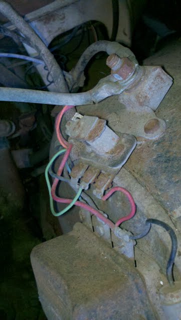
There are two wires one light blue, and one brown, these then run to the passenger headlight I believe, then the horn, and other headlight then to what I believe is the regulator. It is located on the drivers side inner fender. See below:

The alternator has no wires on it. Just a positive post w/ nut, on the back, and two spade clips labled 1 and 2. From what I read both spade clips need some sort of power for the alternator to run properly.
There are two wires one light blue, and one brown, these then run to the passenger headlight I believe, then the horn, and other headlight then to what I believe is the regulator. It is located on the drivers side inner fender. See below:
Last edited by neller840; June 16th, 2011 at 07:03 PM. Reason: picture link was wrong

 August 1st, 2011, 08:28 PM
#10
Registered User
Thread Starter
Join Date: Jul 2010
Posts: 23
Here's what I got so far..
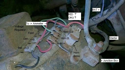
I'm not sure where the red and orange wires originate from.. I'm still working on that, but I am really close to having a new wiring scheme drawn up. Just got my manual so that definitely helps!! If anyone has any ideas or help I'd love to hear them! Thanks again!
August 2nd, 2011, 05:00 PM
#11
Old(s) Fart
Join Date: Mar 2007
Location: Northern VA
Posts: 48,229
The heavy red wire (BATT) on your regulator should be connected to the battery - usually it goes to the threaded junction block post. In any case, the threaded BATT terminal on the alternator connects to this red wire.
The #1 terminal from the alternator connects to the brown wire that runs to the GEN light on the dash, but if you have an ammeter, you may not have a GEN light. In that case, the #1 terminal on the alternator needs to be connected to a switched +12v source with a 35 ohm resistor in series in the wire. This replaces the resistance of the idiot light.
The #2 terminal from the alternator is the sense wire. The correct thing to do is to run it all the way to the junction block so it senses actual voltage there, but it will work if you simply run it to the BATT post on the alternator. That's easier but since it's sensing output voltage right at the alternator it won't adjust the output voltage for the resistance in the wiring over to the junction block.
August 5th, 2011, 06:15 AM
#12
Registered User
Thread Starter
Join Date: Jul 2010
Posts: 23
Thanks Joe for the help once again!! Greatly appreciated!! I am pretty sure I have to use a switched 12v source for terminal #1. Any ideas where to grab a switched 12v source? I'm sure I can find one, just wondered if you had any ideas, for under the hood locations. Hmm I need to look at the wiring diagram again.. Thanks again!! So close!!

Thread
Thread Starter
Forum
Replies
Last Post


