Convertible top will not go down but will go up?????
 June 5th, 2011, 06:03 PM
#1
Registered User
Thread Starter
Join Date: Apr 2011
Location: Cold part of the Midwest!!!!
Posts: 149
Convertible top will not go down but will go up?????
Whats up fellas,
Hope this is the right place for this one. At one point the top went up and down in my 70 Supreme . Today I go to hit the top and it starts to go back then it stopped. I press the button to send it back up and it works and goes back up. I try putting it down again and now nothing is happening no sound or movement from the motor. So i have two questions
1. Is the switch bad on the dash or is this a motor issue?
2. How does one put fluid into the convertible motor and is trans fluid the correct fluid?
I know a couple of you convertible owners can answer this in a snap
Thanks
 June 12th, 2011, 07:18 AM
#4
Registered User
Join Date: Jan 2011
Location: Kansas City
Posts: 38
I have replaced no less than 4 switches in my '67 Cutlass convertible (at $40/pop). I have been through the whole system several times checking for leaks, pressure, etc. What it came down to (in my case) were cheap/foreign switches that kept burning up because of the high amps (~30 or so). My ultimate solution was to install 30Amp relays (one for up, one for down) and replace the switch.
I agree with others though, test the switch first. Do this by removing the switch and isolating the wires. Should be three wires, one is hot and two are to the motor. Connecting the hot to one wire will bring the top up, reversing will bring the top down. If this works, then you know you have a bad switch.
If you're interested in putting relays in to save the cheap switches, let me know and I can provide you a crude wiring diagram. So far this has worked very well for me because the relays isolate the higher amps away from the switch.
I agree with others though, test the switch first. Do this by removing the switch and isolating the wires. Should be three wires, one is hot and two are to the motor. Connecting the hot to one wire will bring the top up, reversing will bring the top down. If this works, then you know you have a bad switch.
If you're interested in putting relays in to save the cheap switches, let me know and I can provide you a crude wiring diagram.
So far this has worked very well for me because the relays isolate the higher amps away from the switch.
June 12th, 2011, 09:08 AM
#5
Registered User
There is also a 40 breaker at the firewall.On my 66 it is behind or below the Brake Booster.Very inexpensive too.Radio Shack may have one for you.
Whatever you do dont give them any of your information Home Address, Telephone Number or EMail Address.Your in trouble.
Whatever you do dont give them any of your information Home Address, Telephone Number or EMail Address.Your in trouble.
Last edited by rroth01; June 12th, 2011 at 09:09 AM. Reason: Grammar
June 12th, 2011, 11:24 AM
#6
Registered User

Join Date: Dec 2006
Posts: 25
My daughter and I bled the convertible lines and refilled the reservoir today due to a leaky connection on the driver-side cylinder (this is fodder for another topic). Top went up and down without any issues.
I stepped away and worked on a few other things and now the top only goes down. I have to push the switch 'UP' just to get the convertible top motor stopped.
Since this sounds like an issue similar to 'leroycjr', I am very interested in advice on testing the switch and the diagram(s) for installing relays.
Scott
P.S. I have a 1971 Cutlass Supreme and I just replaced the Fan Blower relay behind the brake booster.
June 12th, 2011, 04:57 PM
#8
Registered User
Join Date: Feb 2008
Location: Plano, TX
Posts: 11,798
As requested by a member in this thread, here is some info on removing and overhauling of the top's dash switch:
This was pulled from my "120 on cruise control" thread.
-----------------------------------------------------------------
The top switch and bezel was reinstalled like the cruise switch. Its connector was finicky to get back on, but patience paid off and it finally went on. Here is what you are dealing with:
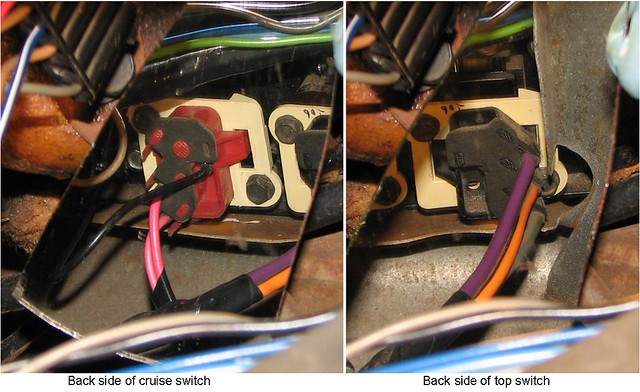
Now since the top switch was pulled out, I figured I should overhaul it� It is a high-current switch, so I wanted to clean it up and wire brush any pitting on the contacts inside with the dremel. Heavy pitting woulf beed a little sanding. The moving parts were lightly greased and the switch reassembled. This simple service is offered by companies for about 60 bucks, even though it is very easy to do!
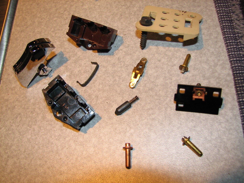
Just take pictures of how it came apart, or make notes on paper.
Here are the guts:
http://www.flickr.com/photos/robsalb...7602930020786/
This was pulled from my "120 on cruise control" thread.
-----------------------------------------------------------------
The top switch and bezel was reinstalled like the cruise switch. Its connector was finicky to get back on, but patience paid off and it finally went on. Here is what you are dealing with:
Now since the top switch was pulled out, I figured I should overhaul it� It is a high-current switch, so I wanted to clean it up and wire brush any pitting on the contacts inside with the dremel. Heavy pitting woulf beed a little sanding. The moving parts were lightly greased and the switch reassembled. This simple service is offered by companies for about 60 bucks, even though it is very easy to do!
Just take pictures of how it came apart, or make notes on paper.
Here are the guts:
http://www.flickr.com/photos/robsalb...7602930020786/
June 15th, 2011, 07:13 AM
#9
Registered User
Join Date: Dec 2006
Posts: 25
Lady72nRob71,
Thanks for the detailed photos and the expert advice. I pulled the left gauge cluster and removed the convt top switch.
Here is what I found:


Can I replace the melted part or do I have to replace the whole thing?
Thanks for the detailed photos and the expert advice. I pulled the left gauge cluster and removed the convt top switch.
Here is what I found:
Can I replace the melted part or do I have to replace the whole thing?
June 15th, 2011, 07:59 AM
#10
Registered User
Join Date: Feb 2008
Location: Plano, TX
Posts: 11,798
Hard to tell with the blurry picture... Are those two pieced stuck together?
If so get them apart and get out the dremel and clean the black off and lets see what is under there. Some sanding and wirebrushing may save it.
If so get them apart and get out the dremel and clean the black off and lets see what is under there. Some sanding and wirebrushing may save it.
June 16th, 2011, 01:02 PM
#11
Registered User
Join Date: Dec 2006
Posts: 25
Lady72nRob71,
No such luck; I can't pull the melted peices apart. Time to buy a new one.
danimal442,
Thanks for the relay diagram. I've ordered the parts and I wonder if you would consider sharing a picture of what the finished wiring should look like?
Did you put the new relays under the dash near the top switch?
June 16th, 2011, 06:45 PM
#12
Registered User
Join Date: Feb 2008
Location: Plano, TX
Posts: 11,798

If you plan to get a new one, it is okay to damage the old one in last attemt to fix it!
I thought those two pieces are metal - are they?
Never saw one that failed like that...
August 15th, 2011, 03:05 PM
#13
Registered User
Thread Starter
Join Date: Apr 2011
Location: Cold part of the Midwest!!!!
Posts: 149
THANKS TO ALL THAT RESPONDED!!!!! Got a very funny story!! So after researching and being lazy I finally said let me buy a new switch....so I did. So saturday I looked at you guys posts and finally pulled it out. Once out I looked at what Lady72 said about the white bezel. Mine looked a little warped so sitting there thinking hmmm wonder if i just hook it up with out the bezel to see if its really the switch. I did and what happened THE DAMN TOP WHEN DOWN AND UP!!! No i was quite entertained that I spend 60 for a new switch but even better the old switch worked. So i heated up the bezel and flatted it out again. Then i put it back in only by touch as I could see NOTHING. So much love to you guys for getting me where i needed to be.
My next biggest thing is I would like to know how to put fluid on the top system.
My next biggest thing is I would like to know how to put fluid on the top system.
Last edited by leroycjr; August 15th, 2011 at 03:07 PM.
August 15th, 2011, 06:41 PM
#14
Registered User
Join Date: Jul 2008
Location: Chi-town
Posts: 4,511
There is a manual (body service manual) you can get for the car and it shows how to rig up a bottle with a tube to fill the motor with hydraulic fluid, messy and not easy - I'll see if I can find the pages in digital format for you
August 15th, 2011, 07:26 PM
#15
Registered User
Join Date: Jan 2011
Location: Kansas City
Posts: 38
Lady72nRob71,
No such luck; I can't pull the melted peices apart. Time to buy a new one.
danimal442,
Thanks for the relay diagram. I've ordered the parts and I wonder if you would consider sharing a picture of what the finished wiring should look like?
Did you put the new relays under the dash near the top switch?
No such luck; I can't pull the melted peices apart. Time to buy a new one.
danimal442,
Thanks for the relay diagram. I've ordered the parts and I wonder if you would consider sharing a picture of what the finished wiring should look like?
Did you put the new relays under the dash near the top switch?
Hi Scott - sorry took so long to reply - Yes, i put the relays up on the firewall behind the switch. I'm not sure I can get a picture of it though - not really a lot of room to maneuver back there. Hope by this time you've got it done....
August 15th, 2011, 07:48 PM
#16
Registered User
Join Date: Feb 2008
Location: Plano, TX
Posts: 11,798
Glad you got it going and that the pics helped.
Read here about top bleeding!
https://classicoldsmobile.com/forums...html#post35862
Read here about top bleeding!
https://classicoldsmobile.com/forums...html#post35862
September 14th, 2011, 02:27 PM
#17

I was looking at your diagram and had a question. The 30amp fuse connects to #30 on the relay but were does the other end connect? is it to #87 on the relay or to the up/down wires coming out of the motor.
September 14th, 2011, 02:49 PM
#18
Connoisseur d'Junque
Join Date: Sep 2010
Location: The Hudson Valley
Posts: 21,183
The diagram says, "This is the harness you pulled off the switch."
That means that the wire to the #30 terminals is the hot wire from the top switch under the dash (alternately, for added oomph, you could run an 8ga wire straight from the battery to the top motor [with a 30A fuse at the battery] and mount the relays behind the back seat where the motor is. You can use the wires that come from the switch as the "Up" and "Down" wires that go to the #85 terminals. Also, even if you do it just like the diagram, you can use only 1 30A fuse if you put it before the wires split).
-Eric
September 14th, 2011, 04:49 PM
#19
CALL ME SLOW if you want but looking at the diagram and the way it looks to me is the power going into the switch is from a 12v source from the fuse box. The up and down wires coming from the switch were connected to #85, #86 was to ground, #87 was to the up and down going into the top motor, #30 to the fuse but what is it connected to? I have a 71 cutlass that has 1 power wire going into the switch and 2 wires coming out going into the top motor. And the top motor has 2 wires coming out and a ground wire.
September 14th, 2011, 06:34 PM
#20
Registered User
Join Date: Jan 2011
Location: Kansas City
Posts: 38
CALL ME SLOW if you want but looking at the diagram and the way it looks to me is the power going into the switch is from a 12v source from the fuse box. The up and down wires coming from the switch were connected to #85, #86 was to ground, #87 was to the up and down going into the top motor, #30 to the fuse but what is it connected to? I have a 71 cutlass that has 1 power wire going into the switch and 2 wires coming out going into the top motor. And the top motor has 2 wires coming out and a ground wire.
Freddy - you're not slow - the +12V at the bottom of the diagram is from your original harness connected to your switch. It is a HIGH AMPS circuit. Depending on your car, that +12V may be coming in from an existing relay under the hood. I said that it goes to your motor in the diagram which isn't strictly speaking true, I just wanted to make the point that this is a DIFFERENT +12V than you would be using if you followed my instructions. If you follow my instructions, you can steal that +12V from just about anywhere since it requires very little draw now.
The principle of a relay is to use a low amp circuit to control another (usually higher amps). This keeps the cheap switches from having to carry that much load, which in turn, tends to burn them up.
Oh, and #30 is as you suspected, the HOT wire of the 3 that goes to your switch currently. You're re-positioning that to the relay if you plan on doing it the way I've detailed.
Hope this helps....
Last edited by danimal442; September 14th, 2011 at 06:43 PM. Reason: updated
September 14th, 2011, 07:21 PM
#21
Connoisseur d'Junque
Join Date: Sep 2010
Location: The Hudson Valley
Posts: 21,183
Freddy -
Here is an alternate diagram of the same relay circuit.
No offense is intended, Danimal, because your diagram is excellent and accurate, it's just that sometimes showing something from a slightly different perspective will make different bells ring for different people.

I have represented the light wires with single lines (���) and the heavy wires with pairs of parallel lines, like a pipe (====).
Note that the +12v supply TO the relays, through the 30A fuse MUST be heavy, as it is a high current wire, but the +12v supply to the to the switch can be either heavy or light wire, as it will have a minimal current drain.
You CAN connect BOTH +12v supply wires to the +12v wire that goes into the top switch if you want to.
Also, here is a picture of my relay setup on my '73 Delta convertible, behind the back seat. Note that the top circuit for the '71 to '75 B-bodies is VERY different, so don't try to trace the wires!

- Eric
Here is an alternate diagram of the same relay circuit.
No offense is intended, Danimal, because your diagram is excellent and accurate, it's just that sometimes showing something from a slightly different perspective will make different bells ring for different people.
I have represented the light wires with single lines (���) and the heavy wires with pairs of parallel lines, like a pipe (====).
Note that the +12v supply TO the relays, through the 30A fuse MUST be heavy, as it is a high current wire, but the +12v supply to the to the switch can be either heavy or light wire, as it will have a minimal current drain.
You CAN connect BOTH +12v supply wires to the +12v wire that goes into the top switch if you want to.
Also, here is a picture of my relay setup on my '73 Delta convertible, behind the back seat. Note that the top circuit for the '71 to '75 B-bodies is VERY different, so don't try to trace the wires!
- Eric
September 15th, 2011, 04:30 AM
#25
Registered User
Join Date: Jul 2008
Location: Seneca Falls, NY
Posts: 5,258
Do you have a brand and part number for the relays you used? I assume they are 30 or 40 amp.
Mike
 September 15th, 2011, 06:09 AM
#26
Connoisseur d'Junque
Join Date: Sep 2010
Location: The Hudson Valley
Posts: 21,183
Here's a diagram I posted showing how to wire up the later scissor top motor:

The relays I used were Tyco T92P11D22-12, which I believe that I got from Mouser.com for about $12-15 each.
- Eric
May 5th, 2012, 06:03 PM
#27
Registered User
Join Date: Dec 2006
Posts: 25
Installed relays today with the help of these links and diagrams. Something is amiss, though.
I have power from the firewall to the 30 amp inline fuses and to the relays ... but nothing after.
Here's my representation of the factory wiring ...

... and here's what I did today ...

Basically, I cut the original wires under the dashboard and inserted the relays.
I did the same thing for the other gray wire.
The diagram I used said to connect the terminals 87a (orange) together ... but that doesn't seem right.
What about the remaining power line (orange w/ black) that goes to the dash switch?
I have power from the firewall to the 30 amp inline fuses and to the relays ... but nothing after.
Here's my representation of the factory wiring ...
... and here's what I did today ...
Basically, I cut the original wires under the dashboard and inserted the relays.
I did the same thing for the other gray wire.
The diagram I used said to connect the terminals 87a (orange) together ... but that doesn't seem right.
What about the remaining power line (orange w/ black) that goes to the dash switch?
May 5th, 2012, 08:19 PM
#28
Connoisseur d'Junque
Join Date: Sep 2010
Location: The Hudson Valley
Posts: 21,183
Wow.
You must be Italian like me, because you sure seem to like spaghetti!
I have taken a close look at your diagram, and will make a number of assumptions based on it:
- I will assume that you used SPDT relays, because you listed terminals 30, 85, 85, 87, and 87b.
- I will assume that the orange wire from the firewall is the hot wire that used to go to the top switch.
- I will assume that the cut end of the orange wire that goes to the switch is not connected to anything.
- I will assume that the blue wire from the firewall is a new wire you ran to the (+) terminal of the battery.
note: This turned out to be a bad assumption.
The blue wire does not go through the firewall to the battery, as the orange wire does - it is connected to ground. - I will assume that you did not put a fuse, fusible link, or circuit breaker between the blue wire and the battery, in a location very close to the battery.
- I will assume that you have connected both 87b terminals to each other.
- I will assume that the pairs of parallel lines interposed between wires indicate interconnections, and not capacitors, as they normally would.
Based on these assumptions, I have drawn a new diagram, showing what you did in a more conventional format. I have used a black and orange line to indicate the connection that needs to be made between the top switch and the (+) feed:
note: This is a new diagram, corrected for the fact that Scott intended to indicate that the blue wires from the relay coils went to ground, and not to the (+) battery terminal. The old diagram is still attached to this post.:

Your diagram looks similar to the arrangement I suggested in my post of 9/14/2011:

Specifically:
- You do not have a 12v supply to the relay coils to make them pull in (that orange wire from the switch that you left hanging).
- You do not have the other sides of the coils (the 85 terminals) grounded, thus allowing the circuit to be completed. Instead, you have them connected to a constant 12v, which would prevent them from working even if you had connected the orange wire to a supply voltage. (a solution to this which would save a bunch of rewiring would be to just ground the orange wire from the switch.)
note: This point is incorrect - Scott actually did connect this side of the coils to ground. - You have connected the 85 terminals to a new, heavy, 12v supply wire, which is unnecessary, as the coils carry only a tiny current - the heavy wire should be for the top motor through the switch contacts of the relays (30 or 87).
- You connected two separate 30A fuses. This is unnecessary, as you could just put a single fuse in the wire before it splits in two, which would have the same effect.
- You put the fuses a distance from the battery - it needs to be within inches of the battery connection, because if something were to cause a short between the battery and the fuse, the wire would be unprotected, and disaster could ensue.
- You have connected the 87a terminals to each other. This will not cause a problem, but is completely unnecessary, and does absolutely nothing.
[If you would connect the parts and wires that you now have in the way that I recommended in my initial drawing, your system would work.
Since you have already connected some of it a certain way, you could have a working system more quickly by grounding the orange wire that is currently coming out of the switch and connected to nothing, and then following my diagram with respect only to terminals 30 and 87 (leaving terminals 85 and 86 alone).]
note: The system is essentially connected the way that I had advised - it's just the diagram that Scott posted that seems to make it look as though it is not.
- Eric
Last edited by MDchanic; May 8th, 2012 at 03:08 AM. Reason: New information from correspondence with poster
May 7th, 2012, 07:05 PM
#30
Registered User

Join Date: Dec 2011
Posts: 7,286
FWIW, I have dozens of them firewall mtd ckt breakers, and very HD relays [SPST].
I have so many that I practically give them away. To Olds folks.
The relays do require 3/8" spade terminals for the high current connections, or you can dremel off part of the tab and use 1/4 spade terms. They have no mtg tab, so you have to improvise- glue a tab on, double sided tape, etc.
One thing I noticed above is that one guy had a single 30A fuse/ breaker split into the feed for the two relays' HD feeds; the other guy split the wire first, then put TWO 30A breakers/ fuses in there. The former is better- you only run ONE relay at a time, so a single fuse can be split to feed the two relays.
May 13th, 2012, 06:33 PM
#31
Registered User
Join Date: Dec 2006
Posts: 25
I wound up pulling the relays out and matching Eric's original diagram. The one key connection that I missed was power/circuit to the switch.
I connected the original orange w/black striped power (hot) wire back to the switch and ran a new 10-gauge wire from the horn relay - through the firewall - to the relays (I spliced a 10-GA wire to connect to the other relay).
As mentioned in the prior post by Octania and MDchanic, I went with one 30-amp fuse a few inches from the horn relay.
After hooking everything back up, I still had no power to the motor. I stepped through the circuit with my test light and found no issues.
Eric (MDchanic) - who is not only a wealth of knowledge but an all-around great guy - talked me down from the cliff over the phone.
Turns out, I somehow pulled the wires away from the switch in the dash. Off came the dash face and the left-most gauge.
After I re-attached the wires to the switch, I can gladly say all is working as planned.
Thanks to all who added their advice and thanks especially to MDchanic.

Thread
Thread Starter
Forum
Replies
Last Post
GoBigRed
Brakes/Hydraulic Systems
15
October 5th, 2015 01:00 PM
75hurstoldsW-30
Parts Wanted
2
September 12th, 2014 06:23 PM
75hurstoldsW-30
Parts For Sale
0
September 8th, 2014 03:18 PM
66olds98conv
Ninety-Eight
8
March 21st, 2013 12:52 PM
455for30y
442
0
June 27th, 2007 12:58 AM


