When you click on links to various merchants on this site and make a purchase, this can result in this site earning a commission. Affiliate programs and affiliations include, but are not limited to, the eBay Partner Network.
1969 Cutlass S Convertible Under Dash Power Top Wiring
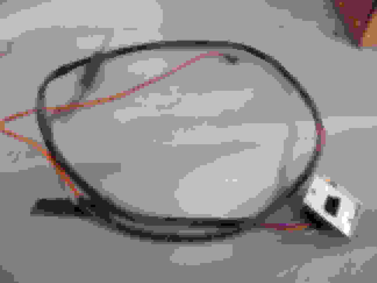
I purchased a 1969 Cutlass S convertible, 5.7 2bbl. I am getting close to the tranny rebuild and getting it licensed. The previous owner apparently had some sort of meltdown, and cut a device out of the system. Usually I could figure this out from wiring diagrams, but being a convertible, I think the relay/switch whatever it was, was convertible related, and I can't find anything in any drawings. Photo is of the three loose wires, and you'll also see a connector (partially melted) with two brown wires. I feel all of these are related. The three wires are the same colors coming from the under dash convertible top switch (orange, Gray and Purple heavy gauge.) Two match the wires on the top motor. (Purple and Gray), The three appear to be wires that had been connected to "something". I'm not sure about the two brown wires, but the connector is exclusive, and it has some melting on it.
Someone hacked the switch out. The orange is the hot lead to the circuit breaker on the firewall behind the brake booster and the purple and gray are up and down (I don't remember which is which).
I don't remember what the brown plug is for but a 69 Factory Service Manual wiring diagram will likely tell you.
Last edited by allyolds68; September 12th, 2019 at 07:31 AM.
Yeah, the switch is still in the dash, and has the wires connected. So this is something else. I thought a relay, but I cannot find that they used one for the top. So what those connected to is still unresolved. I did find someone who told me the two brown wires may be to the heater blower. That makes sense, another high draw electrical item that may have burned up causing the connector to overheat. I will look for that connection next. I will also note that this is a factory AC ar, so good to know, although I don't think it figures in to the top wiring. I did purchase the Fisher manual, so waiting for it to arrive. Thanks for the feedback, and keep sending me your thoughts. I still am at a loss on what was cut out.
Okay, so more information. I just found out the three loose wires go to a Blower Resistor, which is missing along with the 3 wire connector. I can figure that out. I do have a couple more questions. I have a 5 wire blower switch, and have one melted connector, so the switch is gone. I have been completely unable to find anything close. Has anyone found a replacement switch with 5 wires? And lastly, I have a "stacked" connector under dash, also melted, and was disconnected. I have looked all over, through several manuals, can't find what it goes to. They are two brown wires, and I believe they are heater related. Just no idea what they came off of. Any direction is appreciated. I now have a Fisher body manual in addition to my 1969 Cutlass Chassis manual. But neither have been very helpful.
I have a 5 wire blower switch, and have one melted connector, so the switch is gone. I have been completely unable to find anything close. Has anyone found a replacement switch with 5 wires?
The factory switch for A/C uses five wires. I am not aware of any new replacements. Good used will be your only option.
So I am using a substitute blower switch, only 1 original available at $125. That's too high for me. But I had a second issue. I have 3 wires that I am 99% certain went to the Heater resistor. It was cut out of the system. The wires are Orange, Gray and Purple. I purchased a new connector, and a new 3 wire resistor, but I don't know which wire goes where. Anyone have a photo of a resistor with those colored wires running to it? My manual shows yellow, blue and brown. Definitely not what I've got.
Looking deeper under the dash, we found a second connector related to the top wiring, one large gray wire, one large purple. It's not connected. We now believe a previous owner disconnected these wires and bypassed the Convertible top relay. I am now thinking these 3 wires in the original photo are supposed to connect to a power top relay. That said, neither my Cutlass manual, nor my Fischer body manual have drawings of the top wiring. Does anyone have a photo of a 1969 Cutlass power top relay connected? Or any information on the wiring on these?
Reference Mike's photo from post #3 above. The orange wire to the switch is the power feed from the accessory circuit breaker. The purple and grey wires are the UP and DOWN power feeds to the motor. Note the two wire connector in the harness in Mike's photo - is that the one you are talking about? This simply connects the switch wire harness to the body harness that runs back to the pump motor.
So I have the Gray and Purple and Orange Black wires coming from the switch, going under the dash and ending up near the fuse block. Gray and Purple connect to the wires from the motor that run under the carpet. Orange black is hanging near another Orange Black which comes from the fuse behind the brake unit. I also have 3 wires hanging under the dash, again Gray, Purple and Orange black. These run over the steering column, and the Gray and Purple connector is loose hanging there. The Orange wire disappears behind the column, can't trace it. Now I'm wondering if I have duplicate wiring, and the 3 wire harness hanging loose is not used. So just to ask, is there a relay on these? Besides the "fuse" behind the power brake unit.
I now have a Fisher body manual in addition to my 1969 Cutlass Chassis manual. But neither have been very helpful.
I'll try to provide you w/ what little information I can obtain for you. You should be able to find the electrical wiring for the convertible power top in the Fisher Body Service Manual stuck towards the rear of the manual - it's tough to find them. Look for about 10-15 pages of electrical diagrams.
Be very mindful here, I am not providing diagrams for a 1969 Cutlass. I own a 1971 CS convertible; therefore, I cannot ascertain whether these diagrams are compatible w/ your 1969 convertible. With that said, they may be a good jumping off point for you.
Additionally, I can validate sometime over the weekend for you, but I believe my Purple wire for the convertible power top is a direct feed into the center of the front of the fuse panel. I have not had to attempt to address the wiring for my convertible top since it has always operated as intended. I have, however, in fact traced all of the wires from the Front Wiring Harness to the Rear Wiring Harness as I have removed my dash previously and I have installed new carpeting in my vehicle.
Therefore, use these w/ some caution since they are not from the 1969 Fisher Body Service Manual.
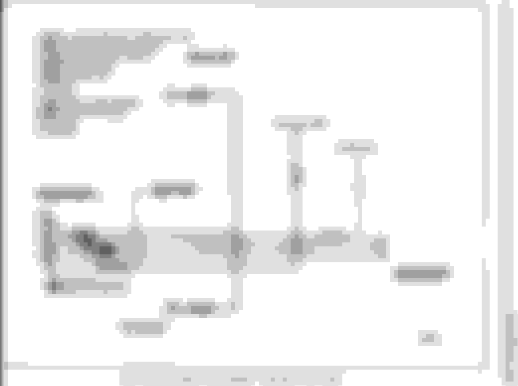
NOTE: The above diagram is from the 1972 Assembly Manual. I can find the one from my 1971, it most likely is the same - just be cautious it is not 1969. NOTE: The plug connector into fuse panel I believe is the purple wire - I can validate this for you sometime this weekend.
NOTE: Gray is UP, Purple is DOWN. NOTE: How this Front Harness connects to the Rear Harness (below). NOTE: Color of wires and schematic description of wires.
I do have a 1969 Factory Assembly Manual.
NOTE: This is the diagram of the firewall demonstrating the connection to the circuit breaker.
NOTE: I have not had to become involved in this circuit breaker on my 1971 CS convertible. Therefore, I cannot speak to the wiring. I can validate for you over the weekend if you want me to examine my own 1971 CS wiring.
This may assist you in addressing your question regarding a relay. It "appears" the wiring is routed through one of those "block" type circuit breakers (I am not certain - I'd have to examine my own). Be mindful, many CO members do not own a convertible; therefore, you may not expect to receive as many responses in a timely manner since convertibles do have selective wiring requirements which depart from the normal wiring (to some degree) and/or have additional wiring requirements which many CO members may not have first-hand experience.
From the above figure (Post #13) note in the upper LH corner the POWER FEED CABLE & note the (SEE FIGURE ONE FOR COVER).
I have zoomed-in on FIGURE 1 (which you can clearly see) - is the block type circuit breaker I made reference to. I am not certain I have the exact same diagram/schematic on my own 1971 convertible; yet, it is clearly demonstrated in the 1969 Factory Assembly Manual.
Now I'm wondering if I have duplicate wiring, and the 3 wire harness hanging loose is not used. So just to ask, is there a relay on these? Besides the "fuse" behind the power brake unit.
Yes, you have duplicate wiring.
No, there is no relay, just the circuit breaker
I appreciate the fast and detailed responses from both you Joe, and Vintage Chief. The information is valuable beyond what you know. The manuals are just not very clear on the convertible wiring. But yes, I was able to find the convertible wiring in the electrical section in the Fischer manual finally. It consists of showing the purple and gray going from the firewall harness, through one connector, to the power top motor. They don't even show the switch! Funny......in some warped way. I do have that circuit breaker on the firewall under the brake unit. So I believe there is no relay, the breaker covers any wiring faux pauxs. It has a Red heavy wire running to the horn relay, and an Orange Black heavy wire running to the inside of the car. The switch wiring does come down and connect to that Orange Black, with the heavy Gray and heavy Purple going to the connector to the motor. I do have that second top wiring harness that runs under the column, it's shorter than the one going to the switch, but it does appear to be "extra" wiring. It disconnected on both ends, so I will leave it disconnected. The switch has been tested using a meter, and it does work. I've got a tri five power top motor I'll be selling, so I can buy the correct one for this car. The only electrical problems this one has was in regard to the heater blower, and although not tested yet, I think I have most of that fixed. Again, all the help is most appreciated. Once I have both systems working, I'll post a reply with the actual wiring and how it all came together. This has been frustrating for me, but a learning experience. I'm possibly a week away from having this baby in for a tranny rebuild. And possibly having its first plates on it for probably 20 -30 years. So it's worth it!
Joe had addressed your question regarding no relay, just the circuit breaker. I was just in my man-cave to validate on my own before Joe posted. My power top wiring employs the same type block circuit breaker as depicted in the diagram (above). In a different location than the 1969, but still only the circuit breaker.
Regarding my statement pertaining in Post #12 "NOTE: The plug connector into fuse panel I believe is the purple wire - I can validate this for you sometime this weekend." That is incorrect. The electric wire spade for my electric windows is inserted into the IGN (center bottom) of the front of the fuse box.
[On a side note - it would appear I'm entering fall/winter mechanical down time mode - in which I generally perform routine maintenance/upgrades/restorations on vehicles. I had only planned to renew the registration on my Indian motorcycle this morning (which requires a safety emissions test); but the Indian wouldn't fire up. Now I have my motorcycle disassembled, I need to R&R the ICP valve & sensor on my 2003 F350 6L diesel and purchase the parts for the rebuild of the suspension on the 71 CS). Coffee tastes damn good this morning though.
...the purple and gray going from the firewall harness, through one connector, to the power top motor. They don't even show the switch!
If you examine that diagram I provided (above in Post #12) from the 1972 manual, you can see the switch and the x3 wires. I suspect it's the same as your 1969.
Originally Posted by Jimp777
...I do have that circuit breaker on the firewall under the brake unit....It has a Red heavy wire running to the horn relay, and an Orange Black heavy wire running to the inside of the car. The switch wiring does come down and connect to that Orange Black, with the heavy Gray and heavy Purple going to the connector to the motor.
Indeed, after just visualizing my own on the vehicle - same.
Regarding my statement pertaining in Post #12 "NOTE: The plug connector into fuse panel I believe is the purple wire - I can validate this for you sometime this weekend." That is incorrect. The electric wire spade for my electric windows is inserted into the IGN (center bottom) of the front of the fuse box.
This is confusing the issue. Once again, there is no connection from the power top circuit to the fuse box. There are only three wires in the circuit. The orange wire runs from the circuit breaker to the switch to provide power. The grey and purple wires are motor UP and DOWN power from the switch to the motor. You can see the purple and grey wires in a standalone cable in this wiring diagram at the lower left. Note the two-terminal connector on the end of those purple/grey wires that is exactly the connector shown in the photo of the switch above. That's all there is. Let's not make it any more difficult.
This is confusing the issue. Once again, there is no connection from the power top circuit to the fuse box. There are only three wires in the circuit. The orange wire runs from the circuit breaker to the switch to provide power. The grey and purple wires are motor UP and DOWN power from the switch to the motor. You can see the purple and grey wires in a standalone cable in this wiring diagram at the lower left. Note the two-terminal connector on the end of those purple/grey wires that is exactly the connector shown in the photo of the switch above. That's all there is. Let's not make it any more difficult.
This was already addressed in my previous Post follow-up. Additionally, I stated: "NOTE: Gray is UP, Purple is DOWN. NOTE: How this Front Harness connects to the Rear Harness (below). NOTE: Color of wires and schematic description of wires." That is pretty clear regarding the color of the wires and the purpose of the wires. I believe [since he couldn't find the wiring diagram(s)], this information provided some level of detail regarding the Gray & Purple wires leading to the motor.
Perhaps I'll grab the ladder, head onto the roof and tackle some basic hurricane Dorian roofing repairs, instead. I've had enough vehicle conundrums to begin my lovely Saturday golf day. LOL Good luck.
I do appreciate all the info. and yes, I have things under control I believe now. Three wires, Purple and Gray go from switch to Motor, orange Black is the power in, and comes from the circuit breaker. All good info, and got me through my own frustration points. It was the extra harness that has confused all my wiring. I do plan to locate those "extra" wires and mark them for future reference, whether my own or a future owner. My next system is the heater/blower. I have a used switch (5 connector as my care is an AC model) and once that's tested, rebuilt if necessar, and installed, I should be able to put my under dash together. On carburetor rebuild away from running again, and then taking in for the tranny. Things should get exciting from here! Thanks again for the help.

 September 11th, 2019, 10:42 AM