1/2 Line, Regulator, and Electric Pump Install
 March 17th, 2014, 06:32 AM
#1
Registered User
Thread Starter
Join Date: Jul 2006
Location: Manassas, VA
Posts: 694
1/2 Line, Regulator, and Electric Pump Install
Here's a generic install thread for installing 1/2" aluminum fuel line, return line, bypass regulator, and an electric pump. This is in a 68-72 A-body ('72 442 clone), but can be applied to just about any body. Keep in mind this is a street car which will be daily driven, and not a show or track car. Functionality is first and foremost, as well as a reasonable degree of safety.
Try to hold off on comments until I get the whole thread posted, please.
First, I laid out the fuel system roughly on a cocktail napkin, just to get an idea of what to initially order parts-wise. My list consisted of a Holley HP150 pump, a Holley billet bypass regulator, RobbMC 1/2" pickup, a 25' coil of 1/2" aluminum fuel line, and assorted AN -8 fittings, push-loc and braided hose.
The tank I'm going to use is an OE one, Spectre, one I replaced not long ago. Suggestion: If your tank is of questionable origin or original, replace it. I think I paid $175 for the one I have, which was with straps and filler neck installed.
Here you see a pic of what I purchased, some odds & ends stuff not shown. I also didn''t use all of what I have shown, since I bought extra stuff, like fittings, so I didn't have to go back and forth ordering and waiting to complete the install. (will explain some later in the thread)
.
 March 17th, 2014, 06:33 AM
#2
Registered User
Thread Starter
Join Date: Jul 2006
Location: Manassas, VA
Posts: 694
First, I gutted all the OE lines. In some of the pics you can see red lines, which shows roughly where I cut the OE lines to remove them. I also removed all the OE retaining clips, and areas where I couldn't get clear pics of the clips, I circled the bolts/screws.
The OE line is mostly likely brittle if it's original, and is cake to cut even with a cheezy mini-hack. You can go 2/3 of the way through and bend it a little, comes right apart. (kinda scary actually)
.
The OE line is mostly likely brittle if it's original, and is cake to cut even with a cheezy mini-hack. You can go 2/3 of the way through and bend it a little, comes right apart. (kinda scary actually)
.
March 17th, 2014, 06:34 AM
#3
Registered User
Thread Starter
Join Date: Jul 2006
Location: Manassas, VA
Posts: 694
Next, I picked a location on the firewall for the bypass regulator. One thing to keep in mind is that locating the regulator on the firewall may NOT be legal for some types of racing, and honestly, I have no clue which those would be, so you may need to check if you plan to race.
Choose a location to the left of the firewall, keeping in mind the output should roughly be high/low enough, and somewhat lined up, with the carb feed line area(s). In my case, I'm running a Holley 4150 type carb, so you can see in the parts pic above I ordered a dual feed. Also, in my case, I had to eyeball it, since currently, the engine isn't in the car!
While I was choosing a location, I also was thinking about retaining clips for the hard lines, and found that one of the A/C box retaining studs was perfect for a clip. (red circle in pic)
I had to relocate the coil to mount the regulator in a spot I was happy with, and wow, I REALLY hate drilling holes in OE metal. Anyway, to fill the original holes, I found some black plastic plugs that do this perfectly from a place called Widgetco.com.
.
March 17th, 2014, 06:34 AM
#4
Registered User
Thread Starter
Join Date: Jul 2006
Location: Manassas, VA
Posts: 694
Some may choose to install a small fuel PSI gauge in the regulator. If you want, ok, but, don't even reply on it to provide any kind of accurate measurement. (They look cool though).
Right way to do it is use a real, full size gauge, and make a 'tool' that can plug into a tap on the fuel rail, like the pic attached. The dual feed line setup I have has 2 'T' fittings on it, the one, unused end has a AN cap which can be removed and used for setting fuel pressure.
.
Right way to do it is use a real, full size gauge, and make a 'tool' that can plug into a tap on the fuel rail, like the pic attached. The dual feed line setup I have has 2 'T' fittings on it, the one, unused end has a AN cap which can be removed and used for setting fuel pressure.
.
March 17th, 2014, 06:35 AM
#5
Registered User
Thread Starter
Join Date: Jul 2006
Location: Manassas, VA
Posts: 694
Ok, with that speech over, we can move on to running the front hard line sections. I measured roughly with a tape measure from the regulator, down the firewall towards the passenger side, and then like 2/3rds of the way down the frame rail. As an example, I measured out 6', which left some room to play with.
So, I rolled out the aluminum line measuring out one 6' section, and one 5.5' section, to leave room for the connectors, so their' not stacked up.
Tip: Rolling out aluminum line is as easy as putting it on a hard, flat surface, hold the open end down, and grabbing around the 10 o'clock position, push down and forward and unroll it. This is a pretty good way of making it pretty straight. Doing it by hand will make it all wavy, but if you want, you can do it that way, it kinda doesn't matter.
With the 2 sections of hardline cut and straightened out, lay them roughly into place along the path chosen. I used the forward OE mount point for the retainer, and using a 3/4" adel clamp (that I slightly crushed with pliers) bolted the lines roughly in place. (you can see the staggered ends in the one pic)
Next, I pushed and persuaded the lines more into the final place, separated the feed and return, lining them up with the regulator ports, and marked the lengths.
.
March 17th, 2014, 06:36 AM
#6
Registered User
Thread Starter
Join Date: Jul 2006
Location: Manassas, VA
Posts: 694
Since I was happy with the front sections, length, location, etc, I can install the ends. On the front sections, I decided to do tube nuts and flare it. Hope I don't need to mention that AN flares are 37 degrees, and not the same degree as brake fittings, so you need an AN flare tool. You can choose to use compression fittings, but they are a touch more expensive.
So I flared one end of both lengths, slipped some heat barrier sleeving over it, then flared the other ends.
After, I installed the front lines starting at the regulator, adjusted the location of the sleeving, and put the retaining adel clamp on.
.
So I flared one end of both lengths, slipped some heat barrier sleeving over it, then flared the other ends.
After, I installed the front lines starting at the regulator, adjusted the location of the sleeving, and put the retaining adel clamp on.
.
Last edited by HWYSTR455; March 17th, 2014 at 09:42 AM.
March 17th, 2014, 06:36 AM
#7
Registered User
Thread Starter
Join Date: Jul 2006
Location: Manassas, VA
Posts: 694
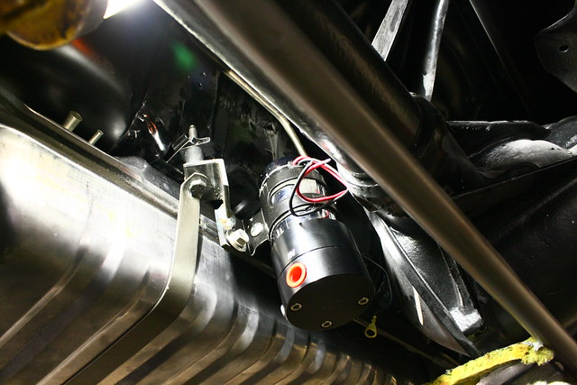
Next I mocked up the pump to see where possible mounting locations are. Some may scrutinize my choice, and some of the pics make it look close, but after it was said and done, it works. (And I didn't have to drill holes in OE sheet metal) Keep in mind also that when using a RobbMC pickup, you will always have to suck fuel up to some degree.
I choose to mount the pump to a plate that saddles a tank strap. Although there's not a pic showing it, I did mock it up with the pre-filter installed. I also put a swatch of dynamat on the tank and on the plate, to help any transfer of sound.
So with that figured out, I dropped the tank so I could install the pickup.
.
March 17th, 2014, 06:37 AM
#8
Registered User
Thread Starter
Join Date: Jul 2006
Location: Manassas, VA
Posts: 694
So I've heard some talk about how they have issues with RobbMC pickups sucking air once below a half a tank. To check this, I measured the tank depth, then the RobbMC pickup, and compared to the OE pickup.
When I installed the OE pickup originally, I cut the sock away from the plastic mounting nipple, and didn't just jerk the whole nipple off. That is shaped like a 'fork', and in the picks, you can't see that fork. But, as a comparison, the OE pickup is a 1/4" longer than the RobbMC pickup. Without the nipple, both pickups would be the same, fyi.
I originally purchased fuel cell pickup line, with the intention of extending the pickup, but decided I would just live with it, since I don't feel a 1/4" is going to make that big of a difference.
FYI - The fuel gauge in the car is aftermarket, and required swapping the sending unit, which was no problem, the RobbMC sender is mounted with screw brackets.
.
March 17th, 2014, 06:38 AM
#9
Registered User
Thread Starter
Join Date: Jul 2006
Location: Manassas, VA
Posts: 694
On to running the rear hard lines. I followed the OE path, until I got to the rear frame cross brace. There I cut in front of the top body bushing and went towards the driver side, then over the brace in the middle of the car.
I fed the first line through from the front, worked it in a curve up, then a curve over, then a curve back. Be careful when working the tubing, have patience, you don't want to make any drastic bends because it will kink. It's aluminum, so it bends easy, just work in as long a section as you can.
After I got the first line routed, did the same for the second line, and worked them into position.
.
March 17th, 2014, 06:39 AM
#11
Registered User
Thread Starter
Join Date: Jul 2006
Location: Manassas, VA
Posts: 694
With the rear lines in place, I worked them more into the final locations, cut them to length, and used the compression fittings to terminate them. Since these were in a more difficult area, like already in place, it was way easier than trying to flare them. I used male ends above the rear so not to have to worry about adapters and tightening.
Once the one ends towards the front were terminated, I connected them to the front lines.
NOTE: I had the car jacked up with jack stands on the rear so the suspension was compressed, and was able to determine that it would contact the bump stops before it would strike the lines.
.
Once the one ends towards the front were terminated, I connected them to the front lines.
NOTE: I had the car jacked up with jack stands on the rear so the suspension was compressed, and was able to determine that it would contact the bump stops before it would strike the lines.
.
March 17th, 2014, 06:40 AM
#12
Registered User
Thread Starter
Join Date: Jul 2006
Location: Manassas, VA
Posts: 694
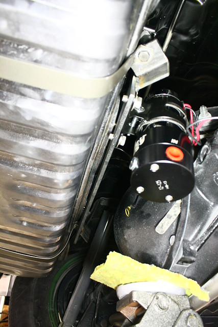
With the hard lines in place, I tossed the tank in there, mounted the pump, and used red Loctite on the bolts.
Then I started measuring for the lines in the rear. I used push-loc stuff back here, way easier to work with. I put the fittings on all the ends, eye balled the routing, then put one end on the hose, and measured the lengths, cut, and assembled. On the one length, it was 4" from an exhaust pipe, so I used some more heat sleeving.
Oh, one thing you may want to do is mark the pickup with feed and return so you don't get them mixed up. Same with the runs front to back.
.
March 17th, 2014, 06:40 AM
#13
Registered User
Thread Starter
Join Date: Jul 2006
Location: Manassas, VA
Posts: 694
Finally, wiring the pump. I made a small harness with a fuse holder and a relay, put the ends on it, and plan to mount it to the amp board I have in the trunk. I did drill one hole in the trunk floor, close to the rear seat, where I plan to run the power wire to the pump, using a grommet. If you really wanted to, you could snake it through the tank vent/separator behind the back seat, up to you.
My relay and fuse setup will be in the trunk, but for most, you could put that under the dash and just run the power wire back to the trunk and to the pump. If you do, use quality 12ga wire to power the pump, and obviously, make sure the ground is good.
I'm sure I missed stuff, and I have a ton of pics, so if there's any questions, fire away.
.
March 17th, 2014, 06:41 AM
#14
Registered User
Thread Starter
Join Date: Jul 2006
Location: Manassas, VA
Posts: 694
Just as an FYI, if you sump your tank, you can run the lines in the OE location, and continue along the passenger side frame rail and exit behind the tank. That would allow you to run the pump in the back behind the bumper. You could run a power wire through the trunk gas gauge grommet.
.
.
 March 17th, 2014, 07:41 AM
#17
Registered User
Thread Starter
Join Date: Jul 2006
Location: Manassas, VA
Posts: 694
Thanks! It is a pretty easy job, and just have to take your time and use common sense. As long as you don't kink a line you are golden.
This type of system will support like 650+ hp, so there's plenty of growing room. With the bypass/return, and 6psi or so, it will eliminate any vapor lock issues too.
The Holley mechanical 80gph pump I had would fall down at the top of 2nd and 3rd gear. And that was with a mild 350. If you just let off a sec and stabbed it again, it would pick right up. It also would suffer from heat soak, the hotter it was, the worse the fall-down would be, and it would also ping from leaning out.
.
March 17th, 2014, 07:43 AM
#18
Registered User
Thread Starter
Join Date: Jul 2006
Location: Manassas, VA
Posts: 694
March 17th, 2014, 07:50 AM
#20
Registered User
Thread Starter
Join Date: Jul 2006
Location: Manassas, VA
Posts: 694
.
March 17th, 2014, 07:57 AM
#21
wait.... what....
Join Date: Mar 2009
Location: London Ont Canada
Posts: 817
It's probably a bit overkill (usually how things i do end up lol) but we were thinking on using a spacer on the bolt on both sides of the tank and welding a piece of flat bar from one side to the other. I just want something solid, and don't want to put any holes through the trunk.
March 17th, 2014, 10:38 AM
#24
Beer Connoisseur
Join Date: Aug 2008
Location: Daly City, California
Posts: 2,090
It's probably a bit overkill (usually how things i do end up lol) but we were thinking on using a spacer on the bolt on both sides of the tank and welding a piece of flat bar from one side to the other. I just want something solid, and don't want to put any holes through the trunk.
March 17th, 2014, 11:19 AM
#26
Beer Connoisseur
Join Date: Aug 2008
Location: Daly City, California
Posts: 2,090
Correction on my previous post I meant to say driver's side not passenger.
I've seen them too, the whole pump just hangs under the bumper, not my style.
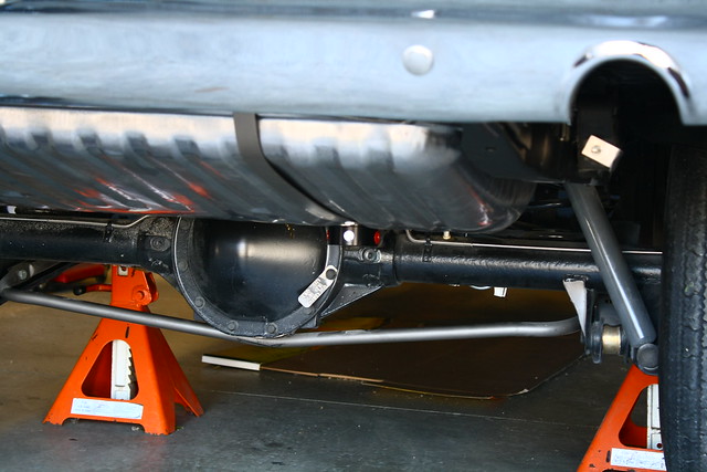
If mounted in the corner you can barely see the bottom of it and the back of my car is on jack stands right now(in process of installing the fuel pump and rear control arms). You have to look 2x to notice that there is something there. I don't think it will be visible at all once the car is on ground. I'll post a picture later on this afternoon.
I've seen them too, the whole pump just hangs under the bumper, not my style.
If mounted in the corner you can barely see the bottom of it and the back of my car is on jack stands right now(in process of installing the fuel pump and rear control arms). You have to look 2x to notice that there is something there. I don't think it will be visible at all once the car is on ground. I'll post a picture later on this afternoon.
March 18th, 2014, 04:13 AM
#28
Registered User

Join Date: Oct 2009
Location: Erie,PA
Posts: 3,814
One thing you need to consider about electric pumps is that they are "pushers".They are meant to push the fuel forward.They don't have teh same ability to pull,like a mechanical.It should be fine for your application,but in a street/strip application,you might find yourself starving for fuel,eventhough the pump is more than capable.This is why they are mounted low & behind a sump.Gravity fed,and the force of the motion sends the fuel backward,into the pump.
The lines look good.I used the 1/2 aluminum coil when I did my 70. I removed the factory lines from the frame,then sat in my driveway,and bent the aluminum line to match the factory lines & curves.It looks exact,with the exception of being larger.The only thing is you need to have the body up from the frame to get the lines in & out without issue.
The lines look good.I used the 1/2 aluminum coil when I did my 70. I removed the factory lines from the frame,then sat in my driveway,and bent the aluminum line to match the factory lines & curves.It looks exact,with the exception of being larger.The only thing is you need to have the body up from the frame to get the lines in & out without issue.
March 18th, 2014, 05:04 AM
#29
Registered User
Thread Starter
Join Date: Jul 2006
Location: Manassas, VA
Posts: 694
Very true about electric pumps being pushers Brian, and when at all possible, sump and have the pump gravity fed. Not possible to do without a sump or with the OE/RobbMC pickup.
In my case, it's a very short distance, like 14"-16", and about as best it can be without a sump. I didn't want to add a sump, and didn't particularly want to mount the pump behind the bumper in this car. It's rare this car will see the track, slicks, or any big HP numbers, so it will be fine I believe.
Spectre now makes EFI ready tanks that are OE on the outside, and use an EFI style in tank pump and sump. You can use one of those and an EFI/Carb regulator like the one Aeromotive makes to knock the psi down to a usable 6-7 psi for a carb. My issue was I already had the tank and didn't want to buy another.
I did a custom stainless tank for the LeMans, Rock Valley built it to my design, has internal baffling, and an integrated sump. I had a cutout added and a plate, to use as a pump/filter mounting arrangement. The pic show it before it went in, and I have since switched to a Holley HP150 setup. This tank is EFI ready.
The Trans Am I did the same, but since it's an EFI car and will probably do hard turns, I made a more elaborate baffle/surge tank inside, with one way check *****, in a 18" x 18" box. That won't suck air, and can probably burn down to a gallon of gas.
True about the lines too, if you do one piece, you have to either lift the body or work it in from the side. You can pull the passenger rear tire, pull the body bolts, and pry up on or jack the body. You can snake it in from the side, but it's not fun. You still have to bend it and bend it back to shape when in position.
.
Last edited by HWYSTR455; March 18th, 2014 at 05:10 AM.
March 18th, 2014, 06:09 AM
#30
Registered User
Join Date: Oct 2009
Location: Erie,PA
Posts: 3,814
The Robbmc pickup was also intended to compliment his mechanical pump.
There are a few other submersible kits out there now,that will go inside an OEM tank. However,I don't think they support big power.
When I converted the 72 to EFI,I got a stealth tank from ricks,and have an A1000 pump inside.
There are a few other submersible kits out there now,that will go inside an OEM tank. However,I don't think they support big power.
When I converted the 72 to EFI,I got a stealth tank from ricks,and have an A1000 pump inside.
March 18th, 2014, 09:28 AM
#31
wait.... what....
Join Date: Mar 2009
Location: London Ont Canada
Posts: 817
Well this is what i managed to cup with to come up with today. I still need to pull it back out and make it look good. I cut a couple "spacers" out of round stock and drilled them through. I then cut a couple pieces of angle iron, drilled a couple holes through them and then welded the round stock to the angle iron. Then i put those pieces in place, took the measurement of the flat bar, and welded the flat bar to the angle iron. Once i had the bracket made i drilled and tapped holes in the flat bar for the pump. Once i got the whole thing mounted in the car with the pump, it's super solid! I jacked up the rear end until i started jacking up the car, and there's plenty of room around it. Once i pull it out to paint i will take more pics of the bracket so you can see it better. I know the fuel pump is backwards in the bracket, i tried different ways of mounting it at first, and just haven't turned it around yet.
March 18th, 2014, 10:13 AM
#32
Registered User
Thread Starter
Join Date: Jul 2006
Location: Manassas, VA
Posts: 694
That looks pretty good! Yeah, I have the w-27 type cover, sucks up a lot of room back there. I'm going to play around a little more too, see what i can come up with, but will probably wait until after I have the engine back together. Nothing wrong with what I've got, really, but would prefer something a little more 'professional' looking.
Hope you don't mind, some of the guys on the pontiac forum were instersted in your setup, and I posted your pics over there too.
.
Hope you don't mind, some of the guys on the pontiac forum were instersted in your setup, and I posted your pics over there too.
.
March 18th, 2014, 10:41 AM
#33
wait.... what....
Join Date: Mar 2009
Location: London Ont Canada
Posts: 817
No i don't mind, maybe if more people posted stuff like this we can get it done right and perfected lol. I google searched this before i started, and not much came up for A bodies.
March 18th, 2014, 11:53 AM
#34
Beer Connoisseur
Join Date: Aug 2008
Location: Daly City, California
Posts: 2,090
Oldzzy, do you have a filter before the fuel pump?
That was my problem, not enough room for filter and pump in that location, without being too close to the exhaust. That's why I ended up installing the filter in that same location and fuel pump behind the bumper.
Also I am installing a relay that has a trigger. Hooks up to your tach or negative on the coil. When you turn the ignition on it starts the pump for 4-5 seconds, enough to fill the bowls. If it doesn't get the signal from coil(engine not running), it shuts the pump down. It's a precaution in case of an accident
March 18th, 2014, 11:57 AM
#35
wait.... what....
Join Date: Mar 2009
Location: London Ont Canada
Posts: 817
I will have a filter before the pump, i just don't have one yet. The filter will go on the side of the pump towards the middle of the car. I don't know which pump you have, but i couldn't find a spot behind my bumper that the pump wasn't noticeable.
March 18th, 2014, 01:38 PM
#37
Registered User
Thread Starter
Join Date: Jul 2006
Location: Manassas, VA
Posts: 694
I have done searches before too, found nothing. I had to wing it on the LeMans, and then later switched to that custom tank, routing lines and dealing with issues both time. Wish I would have had at least SOME examples!
Pumps too, whew! Have I tried some pumps! Pretty much all of them it seems! Holley blues, reds, blacks, Mallorys, Aeromotives, Carters, all kinds. Noisy, burn ups, overheats, seemed it was a constant struggle. Continuous use is a test for an external pump. Not running a bypass is too. Finally ended up with the HP series pumps and not only do they work great and last, they are dead silent too. I like the HP150 since it doesn't have an internal relief valve, or one that's not set too low. I had one fail initially, but that one I ran deadhead with the regulator that came with it. Went to a bypass and all is good. I have like 7-8 years ( like 75k+ miles) on the one on the LeMans, and have driven like 3 tanks continuous, never a hiccup. And it's so quiet, you have to really listen to even hear if it's running.
A pre-pump filter is a must (100 micron), and I've gotten away without running post filters (40 microns). The Holley HP series pumps list a part number for an Earl's 80 micron pre-filter, which is the one I have, and it's very short/small (good thing).
I originally had a 90 degree swivel fitting on the one side of the pump, and the 90 degree adapter on the filter side, but it was too wide. I switched to a 90 degree elbow on the output side which gave me more room. If I would have done the same on the filter side, I would have gained like 3 inches total in the width.
.
March 18th, 2014, 01:48 PM
#38
Beer Connoisseur
Join Date: Aug 2008
Location: Daly City, California
Posts: 2,090
I choose Edelbrock cause I have the same pump on my Chevelle and it's really quiet.
I agree with pre-pump filter I have a 100 micron aeromotive canister style filter. I heard bigger is better when it comes to pre-pump filter on a gravity fed fuel pump without a sump. I don't know if that's true or not.
I agree with pre-pump filter I have a 100 micron aeromotive canister style filter. I heard bigger is better when it comes to pre-pump filter on a gravity fed fuel pump without a sump. I don't know if that's true or not.
March 18th, 2014, 08:30 PM
#39
Registered User
Join Date: Apr 2010
Posts: 978
Nice job. I'm assuming this is a primarily street driven car. Are you concerned with aluminum oxydation over time? Your set up looks like you probably are headed to the track every so often. I have a couple suggestions. First, if you used self tapping screws to fasten the holders, you might want to use pop rivets. It was pointed out to me that they could come out, and shred a tire on the strip. You might want to consider installing an inertia switch, that would shut down power to the pump, in the event of an accident. Be very careful of your routing anywhere near a heat source, like the exhaust. You might want to pick up an NHRA rule book that outlines some of the safety requirements about routing. Specifically near the flexplate or tunnel. You may also want to consider a rear mounted external shut down switch. My set up is strictly drag racing but has the same concept.
117-1735_IMG.jpg
117-1734_IMG.jpg
117-1733_IMG.jpg
117-1731_IMG.jpg
114-1481_IMG.jpg
117-1735_IMG.jpg
117-1734_IMG.jpg
117-1733_IMG.jpg
117-1731_IMG.jpg
114-1481_IMG.jpg
Last edited by 67 Cutlass Freak; March 18th, 2014 at 08:32 PM.
March 19th, 2014, 05:26 AM
#40
Registered User
Thread Starter
Join Date: Jul 2006
Location: Manassas, VA
Posts: 694
Correct, primarily street driven, with a very rare/occassional track visit. Reliability and performance are the primary objectives. In my opening comments, I suggested anyone who is more focused on racing should look at a rule book.
Not really concerned with aluminum ox, but what were you're thoughts/concerns there?
Screws, only screws I have are the 3 that hold the regulator on the firewall, the clamp/retainer ones are factory, and in the factory locations. Not too concerned with those popping out.
Yeah, was thinking of an inertia switch, or a oil psi setup. I can easily add that later.
The closest the lines come to any exhaust is by the pump, and it's over 4" away easy, if not 6", and I covered it with heat shield tubing. It's less-exposed to heat sources than the factory routing was.
67 Cutlass Freak - Very nice setup!
70cutty - I've been eyeing the Edelbrock pumps, they look good, and have heard they are quiet. And somewhat true on the bigger is better for pre-filters, and Aeromotive is top-notch stuff. It's my go-to brand in general.
Technically, you should be one AN size larger on the feed from the tank/sump to the pump. On the LeMans, the pump feed is AN 10, and AN 8 or 1/2" is after/rest of the system.
oldszzy - Yeah, I couldn't find anything behind the bumper to mount the pump either, and I have the Holley HP150.


