10dn to 12si alternator conversion
 January 24th, 2017, 07:25 AM
#1
Registered User
Thread Starter

Join Date: Jan 2017
Posts: 5
10dn to 12si alternator conversion
I currently have an externally regulated 10DN alternator and want to upgrade to a 12SI internally regulated alt. My voltage regulator is a 2 wire, not a 4 wire. Can anybody tell me how to do this conversion properly
 January 24th, 2017, 09:03 AM
#3
Old(s) Fart
Join Date: Mar 2007
Location: Northern VA
Posts: 47,259

 January 24th, 2017, 10:19 AM
#5
Registered User

Join Date: Feb 2009
Location: Pittsburgh Pa.
Posts: 1,306
check out this animal
Check out this animal. Never say never. GM wiring circuit for Delco regulator number 1119511. I believe these were used on very early GM (not sure what apps) 62 63 64 maybe? It looks like he will need to add a resistor from the switch as there is no indicator lite and only an amp gage . The sense wire can be from whatever point he likes.
January 24th, 2017, 10:21 AM
#6
Connoisseur d'Junque
Join Date: Sep 2010
Location: The Hudson Valley
Posts: 21,183
It's missing its Light (and excitor) and Rotor wires.
It can't work like that.
If it is working, I would like to see how the terminals are jumped on the back of the regulator, and how they're connected on the alternator.
Anyway, connection of the 12si is simple, as Joe said, but in your case, I would ignore the existing wires and run new wires, because someone did something there that was very unusual, and you can't tell what else they might have done.
- Eric
January 24th, 2017, 10:24 AM
#7
Old(s) Fart
Join Date: Mar 2007
Location: Northern VA
Posts: 47,259
Check out this animal. Never say never. GM wiring circuit for Delco regulator number 1119511. I believe these were used on very early GM (not sure what apps) 62 63 64 maybe? It looks like he will need to add a resistor from the switch as there is no indicator lite and only an amp gage . The sense wire can be from whatever point he likes.
January 24th, 2017, 10:26 AM
#9
Old(s) Fart
Join Date: Mar 2007
Location: Northern VA
Posts: 47,259
January 24th, 2017, 10:30 AM
#10
Registered User
Join Date: Feb 2009
Location: Pittsburgh Pa.
Posts: 1,306
Joe check out the diagram. No diodes in a genny. This is for a Delco regulator number 1119511 used with an alternator. Remember this is soon after the switch from gen to alt was made. Note the reg is a single winding unit, similar to what chrysler used at the time.
January 24th, 2017, 10:35 AM
#11
Old(s) Fart
Join Date: Mar 2007
Location: Northern VA
Posts: 47,259
 January 24th, 2017, 10:36 AM
#12
Registered User
Join Date: Feb 2009
Location: Pittsburgh Pa.
Posts: 1,306
It sure looks like 2 wires on the reg to me. Open the reg to see if it is one or two coils. If only one it is wired correct. and there will be only one wire going to the alt plug. What year and model car is this?
January 24th, 2017, 10:38 AM
#13
Connoisseur d'Junque
Join Date: Sep 2010
Location: The Hudson Valley
Posts: 21,183
Joe, as Stellar notes, that's definitely an alternator, and it's definitely got two regulator wires (while the generator cars have three).
That being said, Stellar, I just checked, and the 1961 and '62 both show generators, while the '63 shows the other oddball 3-wire regulator:

I suspect that that 2-wire oddball must have been used on some other GM car, or possibly for such a short period that it somehow didn't make it into the manual.
Either way, his photo seems to show a new (replacement) 4-wire regulator with only two of the wires connected (Field and +12V), and not one of the unusual regulators.
Guess it might help to know the year and model...
- Eric
That being said, Stellar, I just checked, and the 1961 and '62 both show generators, while the '63 shows the other oddball 3-wire regulator:
I suspect that that 2-wire oddball must have been used on some other GM car, or possibly for such a short period that it somehow didn't make it into the manual.
Either way, his photo seems to show a new (replacement) 4-wire regulator with only two of the wires connected (Field and +12V), and not one of the unusual regulators.
Guess it might help to know the year and model...
- Eric
January 24th, 2017, 10:42 AM
#14
Old(s) Fart
Join Date: Mar 2007
Location: Northern VA
Posts: 47,259
The 1119511 was used on Pontiac Tempest, among others. Note that the terminals on the underside of the 111951 that I posted above do not match the schematic in Eric's post. Two of the three terminals are ganged together.
January 24th, 2017, 10:45 AM
#15
Connoisseur d'Junque
Join Date: Sep 2010
Location: The Hudson Valley
Posts: 21,183
Yes, definitely a different regulator than the half-year '63 system with the separate warning lamp relay.
So, Joe, from your photo, it looks as though the 2-wire regulator looks the same as the 4-wire unit, except that it's missing the #2 "Rotor" terminal.
- Eric
So, Joe, from your photo, it looks as though the 2-wire regulator looks the same as the 4-wire unit, except that it's missing the #2 "Rotor" terminal.
- Eric
January 24th, 2017, 10:52 AM
#16
Registered User
Join Date: Feb 2009
Location: Pittsburgh Pa.
Posts: 1,306
Here ya go Joe. A couple more diagrams. Note the 1st one. This reg even looks like a gen reg in size and shape. I think this was the 1st type used after the switch from gen to alt with a lite. I helped a guy with a 62 chevy that used one of these and it was stock .
January 24th, 2017, 02:05 PM
#19
Connoisseur d'Junque
Join Date: Sep 2010
Location: The Hudson Valley
Posts: 21,183
Just connect the 12si as Joe suggested, big red wire to big red terminal, and #2 wire to horn relay post (voltage sensor at power distribution point).
The #1 wire typically goes through the GEN light bulb to the IGN terminal of the ignition switch, but since you've got an ammeter and not a light, I would connect it to a decently heavy (at least 3W) resistor of about 10-15Ω, and from there to the IGN terminal, to provide the exciter function that gets the alternator alternating at low RPMs.
- Eric
January 24th, 2017, 02:35 PM
#20
Registered User
Thread Starter
Join Date: Jan 2017
Posts: 5
It appears for a '65, there are 2 voltage regulators listed. One for a light (4 wire) and one for a ammeter (2 wire). My car has an ammeter, so the 2 wire appears to be correct for my setup. Would one of the conversion adapters that quality power alternators sells work for my set up?
January 24th, 2017, 03:00 PM
#22
Connoisseur d'Junque
Join Date: Sep 2010
Location: The Hudson Valley
Posts: 21,183
They do have a converter that would allow you to connect the 10dn plug to the 12si socket, but at $25, plus shipping, it's a whole lot more expensive than just buying a plug from RockAuto ($1.40), or your local parts store (Standard Motor Products HP3870), and you'd have to rewire it anyway.

- Eric
January 25th, 2017, 06:03 AM
#23
Old(s) Fart
Join Date: Mar 2007
Location: Northern VA
Posts: 47,259
So if you have an ammeter, you have two concerns.
First, does the output of the 12SI exceed the rating of your ammeter? Most ammeters were either 30A or 60A. If you install a 12SI of 63A or higher output, your ammeter is now a fuse.
Second, you still need the exciter wire, as noted. If you don't have a GEN light, you need to run that wire from the #1 terminal on the 12SI through a resistor (about 35 ohm is plenty) to a switched 12V source.
January 25th, 2017, 06:17 AM
#24
Connoisseur d'Junque
Join Date: Sep 2010
Location: The Hudson Valley
Posts: 21,183

But, accuracy and tolerances being what they are, I would suspect that a nominal 63A alternator would be fine with a nominal 60A ammeter. I just wouldn't go any higher than that.
- Eric
January 25th, 2017, 08:14 AM
#25
Out of Line, Everytime😉
Join Date: Dec 2006
Location: Melville, Saskatchewan
Posts: 8,909
Interesting, not very often Joe gets stumped. I am pretty happy with my Summit chrome 70 amp 10 DN alternator. The performance tag said 51 amps at idle and 82 amps at cruise. I would assume it would be too much as well. Make sure you get an actual 12si case, the 100 amp 10si alternators don't last.
January 25th, 2017, 08:18 AM
#26
Old(s) Fart
Join Date: Mar 2007
Location: Northern VA
Posts: 47,259
January 26th, 2017, 12:36 PM
#27
Registered User
Thread Starter
Join Date: Jan 2017
Posts: 5
Guys, if i decided to just upgrade the 10dn from the stock 42amp to a 10dn 63 amp, would the stock wiring and ammeter be able to handle the extra amps?...I can live with the external voltage regulator setup for now. The internal alt conversion with my ammeter setup is a little more than I want to tackle right now
-Stick-
-Stick-
January 26th, 2017, 12:50 PM
#28
Old(s) Fart
Join Date: Mar 2007
Location: Northern VA
Posts: 47,259
Guys, if i decided to just upgrade the 10dn from the stock 42amp to a 10dn 63 amp, would the stock wiring and ammeter be able to handle the extra amps?...I can live with the external voltage regulator setup for now. The internal alt conversion with my ammeter setup is a little more than I want to tackle right now
-Stick-
-Stick-
When done, it will look something like this:
 January 27th, 2017, 03:18 AM
#30
Registered User
Join Date: Feb 2009
Location: Pittsburgh Pa.
Posts: 1,306
Some Cadillacs had the sense (#2) wired from the factory directly to the output post as shown in Joes pic.
If he replaces the 10DN stator with a 63 amp stator and retains the original rotor he can still use the original regulator. I doubt if a rotor for a 63 amp would damage the reg, but I'm not 100% certain about that. I don't think a wiring upgrade is necessary up to 63 amps.
If he wires a 10SI 63 amp, he can run without the #1 wire and use only the #2 and power connected to the output post as shown in Joes pic and it will function like a 1 wire alt. The #1 can be empty. I think this would be the easiest and least expensive. It would also allow him to retain all the original wiring with no cutting in case he should ever want to return to original setup.
January 27th, 2017, 01:21 PM
#31
Old(s) Fart
Join Date: Mar 2007
Location: Northern VA
Posts: 47,259
If he wires a 10SI 63 amp, he can run without the #1 wire and use only the #2 and power connected to the output post as shown in Joes pic and it will function like a 1 wire alt. The #1 can be empty. I think this would be the easiest and least expensive. It would also allow him to retain all the original wiring with no cutting in case he should ever want to return to original setup.
January 27th, 2017, 02:14 PM
#33
Old(s) Fart
Join Date: Mar 2007
Location: Northern VA
Posts: 47,259
You were suggesting ways to not cut the original harness by not using the field wire. My point is that with a 12SI, the field wire that I showed with the resistor simply plugs into the old regulator connector at the wire that did NOT run to the original alternator (the one that goes to the switched +12V source). Use a male spade terminal on the wire with the resistor and no irreversible mods to the original harness are required. The other two wires go to the junction on the horn relay.
January 30th, 2017, 12:52 PM
#35
Registered User

Join Date: May 2013
Posts: 248
What would happen if you ran an externally regulated alternator without a regulator?
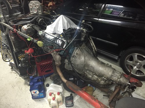
https://flic.kr/p/QVbgD3
If you can zoom in on the upper left hand corner of this test stand setup (onto the back of the alternator) - the '84 (12SI Alternator) plug didn't fit in the alternator so I had to make a temporary conversion harness...that means its a 10DN alternator, correct? And that means it needs a regulator - right? What happens without one?
I'm sorry all my posts sound like "Why is there air?" or whatever but...I got this alternator from a friend just to test. It didn't even occur to me that it could be externally regulated.
I had the voltmeter on the system when I had it running and it seemed to put out 14.4 nuts on the whole time...
 January 30th, 2017, 03:33 PM
#37
Registered User
Join Date: May 2013
Posts: 248
Thanks. The pinout on the spade terminals ("1" & "2") does appear to match that of a 12SI.
What to make of the fact that the white/red molded plug doesn't physically fit into the reliefs in the top of the case housing? Perhaps I have a a "10 SI" - internally regulated, but the plug is of a different configuration?
http://alternatorkit.com/alternators.html
The vent holes on mine match the 2nd 10SI image in the link above.
For comparison - I see that on the 10DN the connections are made from the back (not the top) and are labeled "R" & "F". Also that the back of the 10DN case is markedly different from the SI series.
January 30th, 2017, 03:38 PM
#38
Old(s) Fart
Join Date: Mar 2007
Location: Northern VA
Posts: 47,259
The 12SI is just a newer, higher output version of the 10SI. They are functionally, dimensionally, and electrically interchangeable (allowing for amperage differences). Both are internal regulator designs.
January 30th, 2017, 03:44 PM
#39
Connoisseur d'Junque
Join Date: Sep 2010
Location: The Hudson Valley
Posts: 21,183
The alternator in the photograph is a 12si.
I don't know what setup you may have on your car, but we could tell you more if you could post a few more pictures (and actual pictures are better than Flickr links, as it is tough to find the actual url of the photo within the page's code).
- Eric
I don't know what setup you may have on your car, but we could tell you more if you could post a few more pictures (and actual pictures are better than Flickr links, as it is tough to find the actual url of the photo within the page's code).
- Eric
January 30th, 2017, 03:46 PM
#40
Registered User
Join Date: May 2013
Posts: 248
The alternator in the photograph is a 12si.
I don't know what setup you may have on your car, but we could tell you more if you could post a few more pictures (and actual pictures are better than Flickr links, as it is tough to find the actual url of the photo within the page's code).
- Eric
I don't know what setup you may have on your car, but we could tell you more if you could post a few more pictures (and actual pictures are better than Flickr links, as it is tough to find the actual url of the photo within the page's code).
- Eric


